manuals.online logo
Brands
  1. Home
  2. •
  3. Brands
  4. •
  5. resideo
  6. •
  7. Control Unit
  8. •
  9. resideo V4600 User manual

resideo V4600 User manual

EN1R- 9099 2004R8- NE
V4600/V8600E,T
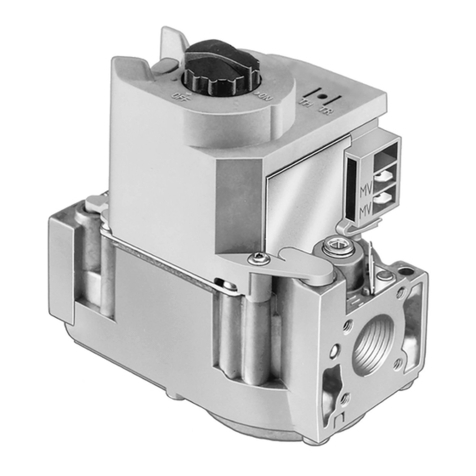
COMPACT GAS CONTROL WITH THROTTLE VALVE
INSTRUCTION SHEET
Dimensions
See fig. 1.
Ambient temperature
0 ... 70 °C
Pipe connection
Pipe connections are designed to meet the bending stress of
group 2 according to EN 161.
Standard:
Inlet: 1/2” ISO 7- 1 internal parallel pipe thread.
Outlet: 1/2” ISO 7- 1 internal parallel pipe thread or
Ø18.6 mm without thread.
Inlet and outlet can also be made with straight or elbow
flanges.
Special connection: Side outlet Ø14 mm
APPLICATION
V4600/V8600E,T gas controls, together with Resideo pilot
burner/thermocouple and room/boiler thermostats, provide all
the functions necessary to safely regulate gas flow pilot
burner and main burner manifold of domestic heating boilers
(free standing and wall mounted), warm air furnaces and back
boilers.
V4600/V8600E,T gas controls are intended to be used for
manufactured, natural and LP gases (1st, 2nd, 3rd family gas).
V4600/V8600E,T gas controls are approved in accordance
with existing european standards.
DESCRIPTION
V4600/V8600E,T gas controls comprise a pilotstat
mechanism, throttle valve and an electric operated on/off
valve.
The pilotstat is a thermoelectric safety device according to
european standards EN 125 and EN 126 and closes off the
gas supply to both main burner and pilot burner.
The electric on/off servo operator is an automatic shut- off
valve of class J according to EN 161 and closes off the gas
supply to the main burner.
SPECIFICATIONS
Models
V4600 serie: 220/240 V, 50 Hz.
V8600 serie: 24 V, 50 Hz.
Suffix E: fast opening and throttle valve
Suffix T: slow opening and throttle valve
Pilot gas connection
Standard at end outlet: 1/4”, 4 mm or 6 mm outer diameter
tubing.
Special connection: Included in the side outlet.
Capacity*
In m3/h air at ∆P of 2.5 mbar.
Pipe conn
ection
Capacity
1/2” x 1/2” 3.15
1/2” x Ø18.6 mm 3.15
1/2” x Ø14 mm side outlet 2.2
* Capacity curves are available on request.
Minimum differential pressure
Between inlet and outlet: 2.5 mbar
Minimum adjustable capacity
1.5 m3/h air at ∆P of 20 mbar
Maximum operating pressure
The Pmax indication on the housing of the gas control is the
maximum inlet pressure at which the gas control functions
safely.
Mounting holes
Two M5 mounting holes are located on the bottom of the gas
control.
The four holes at inlet and outlet for mounting the flange on
the gas control are provided with M5 thread with minimum
6.5 mm full thread.
The four holes for mounting the flange to the side outlet are
provided with M4 thread with min 6 mm full thread.
EN1R- 9099 2040R8- NE
2
Fig. 1. Dimensions and adjustment points
Electrical data
Timing
Closing time: 2 s
Dead time: Suffix E: < 5 s
Suffix T: < 6 s
Opening time:
Suffix E: 1 s from start of flow till 50% of outlet pressure.
Suffix T: 1.5 s from start of flow till softlite pressure
Enclosure (including cover)
IP 40 (with cover or plug)
IP 44 (with plug according to DIN 43650
INSTALLATION
IMPORTANT
Take care that installer is a trained experienced
service person.
Turn off gas supply before starting installation.
Disconnect power supply to prevent electrical shock
and/or equipment damage.
Do not remove seals over gas control inlet and outlet
until the device is ready to be installed.
Working voltage
Current (mA)
Power consumption
(W)
220/240 V, 50 Hz
20.4/24
3.4/4.5
24 V, 50 Hz
211
3.8
3
EN1R- 9099 2004R8- NE
Mounting position
The gas control can be mounted 0 to 90
_
in any direction from
the upright position i.e. from the position when the knob is on
top.
Main gas connection
•
Take care that dirt cannot enter the gas control during
handling.
•
Use a clean taper fitting with thread according to BS 21 or
a piece of new, properly reamed pipe, free from swarf.
•
Do not tighten the pipe or pipe fitting too far (see table
below). Otherwise valve distortion and malfunction could
result.
Pipe s
ize
Max. length of pipe thread
1
/
2
”
18.6 mm
•
Apply a moderate amount of good quality thread
compound to the pipe or fitting only, leaving the two end
threads bare. PTFE tape may be used as an alternative.
•
Ensure the gas flows in the same direction as the arrow on
the bottom of the gas control.
Pilot gas connection
•
Square off the end of tubing and remove burrs.
•
Slip compression fitting over tubing.
•
Insert tubing into gas control housing until it bottoms, slide
fitting into place and turn finger tight.
•
Use a wrench to tighten fitting about
3
/
4
turn beyond finger
tight to make a pressure tight joint.
Do not use jounting
compound.
•
Connect other end of tubing to pilot burner according to the
pilot burner manufacturer’s instructions.
CAUTION
Do not bend tubing at gas control after compression
fitting has been tightened, as this may result in gas
leakage at the connection.
Thermocouple connection
The gas control has an electrical thermocouple connection
and must therefore be kept clean and dry; thread compound
should never be applied to it. Tighten only
1
/
4
turn beyond
finger tight in order to give good electrical connection. When
routing the thermocouple tubing, do not bend it too sharply
(min. radius 2.5 mm).
Perform gas leak test
WARNING
FIRE OR EXPLOSION HAZARD CAN CAUSE
PROPERTY DAMAGE, SEVERE INJURY OR DEATH
•
With the main burner in operation, paint all pipe joints
(including adapters) and gas control inlet and outlet with
with a rich soap and water solutionan approved leak
detection fluid.
•
If another gas leak is detected, tighten adapter screws,
joints and pipe connections.
•
Replace the part if gas leak can not be stopped.
CAUTION
Keep soap and water solution away from electrical
connections.
Electrical connection
CAUTION
Switch off power supply before making electrical
connections.
Take care that wiring is in accordance with local
regulations.
Follow the instructions supplied by the appliance
manufacturer. If there are no such instructions,
see fig. 2. and 3. for typical wiring diagrams.
Use lead wire which can withstand 105
_
C ambient.
The electric on/off servo operator is provided with:
both 6.3 mm terminals suitable for 6.3 mm receptacles (e.g.
”Series 250” AMP fasteners) and screw terminals,
or provided with:
quick connect terminals suitable for 6.3 mm receptacles
(e.g. ”Series 250” AMP fasteners) or for a female connector
according DIN 43650.
Wiring 220/240 V, 50 Hz (see fig. 2.)
Install the line voltage thermostat (or controller) and other
controls as required.
Provide hard PVC boots on the AMP terminals to prevent
touching of life terminals. When fitting a cover a Heyco
-
type
strain relief should be used.
Wiring 24 V, 50 Hz (see fig. 3.)
Install the transformer, low voltage thermostat and other
controls as required.
Adjust heat anticipater to the A rating as stamped on the gas
control.
Check for gas leaks with a rich soap and water
solution any time work is done on a gas control.
Gas leak test
•
Paint all pipe connections upstream of the gas control with
with a rich soap and water solution.Bubbles indicate a gas
leak.
•
If a gas leak is detected, tighten the pipe connection.
•
Stand clear while lighting the main burner to prevent injury
caused from hidden gas leaks, which could cause flasback
Line voltage
Limit control
Thermostat
Valve operator
in the appliance vestibule. Light the main burner.
Fig. 2. Wiring 220/240 V, 50 Hz
EN1R- 9099 2004R8- NE
4
Line voltage
Limit control
Transformer
Thermostat
follow them. If these instructions are not provided then
use the procedure outlined below.
CAUTION
24 Vac
Valve operator
Fig. 3. Wiring 24 V, 50 Hz
OPERATION
The operation of the pilot safety system is accomplished by
manipulation of a knob, provided with programming symbols
that indicate lighting and shutt off.
Lighting
•
Depress knob and hold it down.
•
Ignite pilot burner.
•
Hold knob down for 20 seconds, after pilot burner has
been lit.
•
Release knob.
•
Wait at least three minutes before a second attempt to light
the pilot burner is made, when pilot flame has not been
established.
Shut off
In order to interrupt all gas flow through the gas control, knob
must be turned clockwise to its stop.
After release the knob will automatically rotate to its ready
position.
IMPORTANT
A safety latching device prevents the knob from
being fully depressed until the thermocouple has
cooled down sufficiently to de
-
energize the power
unit, after which the knob will be effective again.
When the knob is depressed during latch position,
pilot gas will flow to pilot burner. However, when
knob is released, pilot gas extinguishes and main
gas supply is not affected.
Wait one minute after shut off before starting lighting
procedure.
ADJUSTMENTS AND CHECKOUT
WARNING
Adjustments must be made by qualified persons only.
If the appliance manufacturer supplies checkout and/
or service and maintenance instructions carefully
To ensure a safe closing of the valve, it is essential
that voltage over the terminals of electric on/off servo
operator is reduced to 0 Volt.
Pressure tap
The gas control is provided with a pressure tap of 9 mm outer
diameter at inlet and outlet side.
When checking the pressure undo the screw a half turn and
slip tube over nipple.
Ensure that screw is retightened after making test.
Pilot flame adjustment (see fig. 1.)
The gas control is packed for shipment with pilot flow at
maximum. Refer to the pilot burner manufacturer’s
instructions for recommended size of pilot flame.
If adjustment is required turn pilot flow adjustment screw
clockwise to decrease or counter clockwise to increase pilot
flame.
Outlet pressure adjustment (see fig. 1.)
•
Energize electric on/off servo operator in order to have gas
input to burner.
•
Check input to the appliance using a clocking gas meter or
alternatively a pressure gauge connected to the outlet
pressure tap.
•
Open cap to expose throttle adjustment screw.
•
Turn the flow adjustment screw with a screw driver
either
way
until the burner pressure required is recorded on the
pressure gauge.
•
Close cap.
Check of slow opening (softlite)
The softlite pressure is factory set.
Check burner performance at this pressure observing burner
ignition and flame characteristics.
Burner should ignite promptly and without flash back to orifice
and all ports should remain lit.
Cycle burner several times (wait 10 seconds between cycles
to allow servo system to resume slow open action).
Repeat check of slow opening after allowing the appliance to
cool down.
Checkout
Set appliance in operation after any adjustment and observe
several complete cycles to ensure that all burner components
function correctly.
Maintenance and service
Under normal circumstances no maintenance or service is
required.
Screws on the valve that have been sealed must never be
removed.
Resideo Pittway Sàrl
Z.A. La Pièce 4
1180 Rolle
Switzerland
TR TH

This manual suits for next models

2

Other resideo Control Unit manuals

resideo Braukmann L5 Series User manual

resideo

resideo Braukmann L5 Series User manual

resideo Braukmann D160S User manual

resideo

resideo Braukmann D160S User manual

resideo Braukmann D05FT User manual

resideo

resideo Braukmann D05FT User manual

resideo V8200 User manual

resideo

resideo V8200 User manual

resideo BA295S User manual

resideo

resideo BA295S User manual

resideo Braukmann BA295D-3/4WHD User manual

resideo

resideo Braukmann BA295D-3/4WHD User manual

resideo Braukmann V5006TF User manual

resideo

resideo Braukmann V5006TF User manual

resideo Braukmann BA295D-1/2ASC User manual

resideo

resideo Braukmann BA295D-1/2ASC User manual

resideo RV283P User manual

resideo

resideo RV283P User manual

resideo Braukmann D05FS-EF User manual

resideo

resideo Braukmann D05FS-EF User manual

resideo SmartValve SV9541 User manual

resideo

resideo SmartValve SV9541 User manual

resideo Braukmann RV280 User manual

resideo

resideo Braukmann RV280 User manual

resideo Braukmann BA295STN-A User manual

resideo

resideo Braukmann BA295STN-A User manual

resideo SV9440 User manual

resideo

resideo SV9440 User manual

resideo Braukmann D15P User manual

resideo

resideo Braukmann D15P User manual

resideo Braukmann D04FM User manual

resideo

resideo Braukmann D04FM User manual

resideo Braukmann D15S User manual

resideo

resideo Braukmann D15S User manual

resideo Braukmann SG160S User manual

resideo

resideo Braukmann SG160S User manual

resideo Braukmann VWS02Y032W-L5 User manual

resideo

resideo Braukmann VWS02Y032W-L5 User manual

resideo RV283P User manual

resideo

resideo RV283P User manual

resideo Braukmann SG150 User manual

resideo

resideo Braukmann SG150 User manual

resideo Braukmann MHF49 User manual

resideo

resideo Braukmann MHF49 User manual

resideo Braukmann D16 User manual

resideo

resideo Braukmann D16 User manual

resideo S8910U User manual

resideo

resideo S8910U User manual

Popular Control Unit manuals by other brands

GEM iComLine CleanStar C57 HPW Installation, Operating and Maintenance Instruction

GEM

GEM iComLine CleanStar C57 HPW Installation, Operating and Maintenance Instruction

VERITAS 16Gb FC SFP Hardware Service Procedure

VERITAS

VERITAS 16Gb FC SFP Hardware Service Procedure

STIEBEL ELTRON KV 30 Operation and installation

STIEBEL ELTRON

STIEBEL ELTRON KV 30 Operation and installation

Sharp NB-JD580 installation manual

Sharp

Sharp NB-JD580 installation manual

Viessmann 5205 Operation manual

Viessmann

Viessmann 5205 Operation manual

Pilz PNOZ mc10p operating manual

Pilz

Pilz PNOZ mc10p operating manual

GF JRGURED LF 1319 Operating and maintenance instructions

GF

GF JRGURED LF 1319 Operating and maintenance instructions

American Standard SELECTRONIC 6590.525 installation instructions

American Standard

American Standard SELECTRONIC 6590.525 installation instructions

Eaton ELC-CODNETM user manual

Eaton

Eaton ELC-CODNETM user manual

VersaLogic VL-MPEu-C1E Hardware reference manual

VersaLogic

VersaLogic VL-MPEu-C1E Hardware reference manual

Thermo Scientific Orion Versa Star reference guide

Thermo Scientific

Thermo Scientific Orion Versa Star reference guide

GOK AUV PS 16 bar Assembly and operating manual

GOK

GOK AUV PS 16 bar Assembly and operating manual

Emerson Alco Controls 110RB Operating	 instruction

Emerson

Emerson Alco Controls 110RB Operating instruction

Yaesu FT-2000 - MENU MODE LIST operating manual

Yaesu

Yaesu FT-2000 - MENU MODE LIST operating manual

Pickering 4 890 Series manual

Pickering

Pickering 4 890 Series manual

CEAG COOPER Crouse-Hinds GHG 664 5 Series operating instructions

CEAG

CEAG COOPER Crouse-Hinds GHG 664 5 Series operating instructions

Beyerdynamic MCW-D 50 manual&nbsp;

Beyerdynamic

Beyerdynamic MCW-D 50 manual&nbsp;

HEIDENHAIN TNC 620 user manual

HEIDENHAIN

HEIDENHAIN TNC 620 user manual

manuals.online logo
manuals.online logoBrands
  • About & Mission
  • Contact us
  • Privacy Policy
  • Terms and Conditions

Copyright 2025 Manuals.Online. All Rights Reserved.