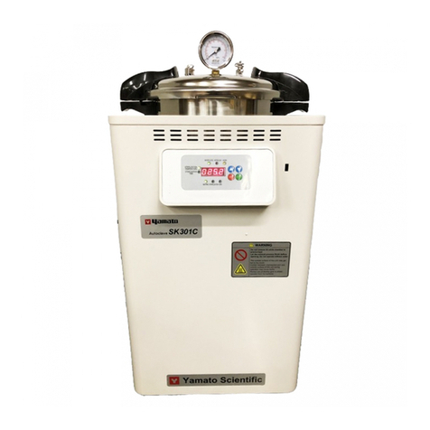
Yamato SK 100C User manual

Sterilizer
Model
SK 100C/110C
Instruction Manual
- Second Edition -
Yamato Scientific Chongqing Co.,Ltd
zThank you for purchasing "Sterilizer, SK Series"
of Yamato Scientific Co., Ltd.
zTo use this unit properly, read this "Instruction
Manual" thoroughly before using this unit.
Keep this instruction manual around this unit for
referring at anytime.
WARNING!:
Carefully read and thoroughly understand the
important warning items described in this
manual before usin
g
this unit.

Contents
Cautions in Using with Safety ................................................................1
•Explanation.................................................................................................................... 1
•Table of Illustrated Symbols .......................................................................................... 2
•Fundamental Matters of "WARNING!" and "CAUTION!" ............................................... 3
•Fundamental Matters of "WARNING!" and "CAUTION!" ............................................... 4
Before Using This Unit............................................................................5
•Requirements for Installation......................................................................................... 5
•Requirements for Installation......................................................................................... 6
•Requirements for Installation......................................................................................... 7
•Installation Procedure.................................................................................................... 8
•Installation Procedure.................................................................................................... 9
Description and Function of Each Part................................................10
•Main Unit ..................................................................................................................... 10
•Control Panel (Keys) ................................................................................................... 11
Operation Method..................................................................................12
•Apparatus/Liquid Sterilization Course ......................................................................... 12
•Apparatus/Liquid Sterilization Course ......................................................................... 13
•Sterilizing Parameters ................................................................................................. 14
Handling Precautions............................................................................15
•WARNING ................................................................................................................... 15
•CAUTION .................................................................................................................... 16
Maintenance Method .............................................................................17
•Daily Inspection and Maintenance .............................................................................. 17
Long storage and disposal...................................................................18
•When not using this unit for long term / When disposing ............................................ 18
In the Event of Failure…........................................................................19
•Safety Device and Error Code..................................................................................... 19
After Service and Warranty...................................................................20
Specification ..........................................................................................21
Wiring Diagram ......................................................................................22
Replacement Parts Table ......................................................................23
Reference ...............................................................................................24
•List of Dangerous Substances .................................................................................... 24

1
Cautions in Using with Safety
Explanation
MEANING OF ILLUSTRATED SYMBOLS
Various symbols are used in this safety manual in order to use the unit without
danger of injury and damage of the unit. A list of problems caused by ignoring
the warnings and improper handling is divided as shown below.Be sure that you
understand the warnings and cautions in this manual before operating the unit.
WARNING! If the warning is ignored, there is the danger of a problem that
may cause a serious accident or even fatality.
CAUTION! If the caution is ignored, there is the danger of a problem that may
cause injury/damage to property or the unit itself.
Meaning of Symbols
This symbol indicates items that urge the warning (including the caution).
A detailed warning message is shown adjacent to the symbol.
This symbol indicates items that are strictly prohibited.
A detailed message is shown adjacent to the symbol with specific actions not to
perform.
This symbol indicates items that should be always performed.
A detailed message with instructions is shown adjacent to the symbol.
Illustrated Symbols

2
Cautions in Using with Safety
Table of Illustrated Symbols
Warning
Warning,
generally
Warning,
high voltage
Warning,
high temperature
Warning,
drive train
Warning,
explosive
Caution
Caution,
generally
Caution,
electrical shock
Caution,
scald
Caution,
no road heating
Caution,
not to drench
Caution,
water only
Caution,
deadly poison
Prohibit
Prohibit,
generally
Prohibit,
inflammable
Prohibit,
to disassemble
Prohibit,
to touch
Compulsion
Compulsion,
generally
Compulsion,
connect to the
grounding
terminal
Compulsion,
install on a flat
surface
Compulsion,
disconnect the
power plug
Compulsion,
periodical
inspection

3
Cautions in Using with Safety
Fundamental Matters of "WARNING!" and "CAUTION!"
WARNING!
Do not use this unit in an area where there is flammable or explosive gas
Never use this unit in an area where there is flammable or explosive gas. This unit is not
explosion-proof. An arc may be generated when the power switch is turned on or off, and
fire/explosion may result. (Refer to page 24 "List of Dangerous Substances".)
Always ground this unit
Always ground this unit on the power equipment side in order to avoid electrical shock due to a power
surge.
If a problem occurs
If smoke or strange odor should come out of this unit for some reason, turn off the circuit breaker right
away, and then disconnect the power plug or power terminal. Immediately contact a service technician
for inspection. If this procedure is not followed, fire or electrical shock may result. Never perform repair
work yourself, since it is dangerous and not recommended.
Do not use the power cord if it is bundled or tangled
Do not use the power cord if it is bundled or tangled. If it is used in this manner, it can overheat and
fire may be caused.
Do not process, bend, wring, or stretch the power cord forcibly
Do not process, bend, wring, or stretch the power cord forcibly. Fire or electrical shock may result.
Substances that can not be used
Never use explosive substances, flammable substances and substances that include explosive or
flammable ingredients in this unit. Explosion or fire may occur. (Refer to page 24 "List of Dangerous
Substances".)
Do not disassemble or modify this unit
Do not disassemble or modify this unit. Fire or electrical shock or failure may be caused.
Do not get close to the vapor outlet / Do not block the outlet
The vapor outlet is provided on the left face of equipment. Do not put your hands or face close to the
outlet. Do not block the outlet. A burn injury or equipment failure may result in.

4
Cautions in Using with Safety
Fundamental Matters of "WARNING!" and "CAUTION!"
CAUTION!
When opening the cover...
Make sure that the pressure of equipment has decreased to 0(zero) MPa before
opening the cover. Generally the cover does not open due to the safety lock
mechanism under the high pressure condition. The high-temperature and pressure
vapor blows out if the cover is forced open under high pressure, which may cause a
burn injury. A large amount of vapor blows out from inside of the chamber when
opening the cover just after the sterilizing operation has completed (when the
temperature inside the chamber is high). Do not put your hands and face close to the
cover.
When draining water...
Make sure that the pressure of equipment has decreased to 0(zero) MPa before draining the sterilizing
water. The hot water blows out if the valve is opened under high pressure. The sterilizing water
remains very hot just after the sterilizing operation has completed even the pressure reading is 0(zero)
MPa. Drain the water after it is sufficiently cooled down.
Do not touch the hot section
Some sections on the equipment such as the circumference of cover or drain bottle are very hot during
or just after the operation of equipment. Do not touch these sections to avoid burn injury.
When taking the sterile samples from the chamber...
Sufficiently remove the vapor inside the chamber before taking the sterile samples from the chamber.
Wear heat-resistant leather gloves to take them from the chamber to protect your hands from
high-temperature samples.
Do not touch the heat releasing outlet
Do not directly touch the heat releasing outlet located around the outer covering. The vapor may blow
out from the safety valve by an accident during sterilizing operation. Do not block the outlet.
During a thunder storm
During a thunderstorm, turn off the power key immediately, then turn off the circuit breaker and the main
power. If this procedure is not followed, fire or electrical shock may be caused.

5
Before Using This Unit
Requirements for Installation
1. Choose a proper place for installation
•Do not install this unit in a place where:
♦Rough or dirty surface.
♦Flammable gas or corrosive gas is generated.
♦Ambient temperature 35°C and above or 5°C and below.
♦Ambient temperature fluctuates violently.
♦There is direct sunlight.
♦There is excessive humidity and dust.
♦There is a constant vibration.
♦Not horizontal surface.
♦The power source is instable.
•Install this unit on a stable place with the space as shown below.
2. Installation on horizontal surface
•Use the equipment on the horizontal and firm
place to keep the water inside the chamber
horizontal. If the equipment tilts and the
heater appears from the water surface, the
temperature on the area above the water
rises and a heater failure or operation stop
due to water level detector function may
occur.
•The weight of main unit is approximately
14kg. Carry and install the equipment
carefully by two or more persons.

6
Before Using This Unit
Requirements for Installation
3. Before/after installing
•It may cause injure to a person if this unit falls down or moves by the earthquake and the
impact. etc..To prevent, take measures that the unit cannot fall down, and not install to busy
place.
4. Ventilate the equipment sufficiently
•Do not block the heat releasing outlets on the side face and back face of equipment during
operation. The temperature inside the equipment rises, which may cause the deterioration or
failure of equipment, accident, or fire disaster.
5. Do not use this unit in an area where there is flammable or explosive gas
•Never use this unit in an area where there is flammable or explosive gas. This unit is not
explosion-proof. An arc may be generated when the power switch is turned ON or OFF, and
fire/explosion may result.
•To know about flammable or explosive gas, refer to page 24 “List of Dangerous Substances”.
6. Choose a correct power distribution board or receptacle
•Choose a correct power distribution board or receptacle that meets the unit’s rated electric
capacity.
•Operating voltage range for respective equipment models are as follows.
models: AC100 to 120V SK110C models: AC200 to 240V
Electric capacity: SK100C: AC100V-120V 9A-12A, SK110C: AC200V-240V 4.5A-6A
NOTE)
There could be the case that the unit does not run even after turning ON the power. Inspect
whether the voltage of the main power is lowered than the specified value, or whether other
device(s) uses the same power line of this unit. If the phenomena might be found, change the
power line of this unit to the other power line.
•Starburst connection with a branching receptacle or extended wiring with a cord reel lowers
electrical power voltage, which may cause the degradation of refrigeration capability.
•Connect the unit to only the power supply. If it is connected to a gas pipe, water pipe or
telephone line, an accident or malfunction may result.

7
Before Using This Unit
Requirements for Installation
7. Handling of power code
•Do not entangle the power cord. This will cause overheating and possibly a fire.
•Do not bend or twist the power cord, or apply excessive tension to it. This may cause a fire
and electrical shock.
•Do not lay the power cord under a desk or chair, and do not allow it to be pinched in order to
prevent it from being damaged and to avoid a fire or electrical shock.
•Keep the power cord away from any heating equipment such as a room heater. The cord's
insulation may melt and cause a fire or electrical shock.
•If the power cord becomes damaged (wiring exposed, breakage, etc.), immediately turn off the
power at the rear of this unit and shut off the main supply power. Then contact your nearest
dealer for replacement of the power cord. Leaving it may cause a fire or electrical shock.
•Connect the power plug to the receptacle which is supplied appropriate power and voltage.
8. Always ground this unit
•Be sure to connect the earth wire (the green cable of power cord) to the grounding conductor or
ground terminal to prevent accidents caused by electric leakage.
•Do not connect the earth wire to gas or water pipes. If not, fire disaster may be caused.
•Do not connect the earth wire to the ground for telephone wire or lightning conductor. If not, fire
disaster or electric shock may be caused.
•Please consult your local electrical contractor for power connecting work.
•Do not use a branching receptacle, which may cause the heat generation.
•The D class earth connecting works is required if no ground terminal is provided. In this case,
consult with the selling office where you purchased or our sales office.
•Securely connect it to the switchboard or outlet.
SK100C
G
G
An earth connecting outlet is recommended
to be used.
SK110C
These models do not include the power plug.
Correctly connect the ground to fit with the
power supply facility to be connected.
9. Connect the power cord paying attention to the color of each core wire
•When connecting the power cord, do check the breaker
on the electric power equipment be "OFF". Note that
SK100C and SK110C do not equip with the power plug.
Select and connect the appropriate plug or terminal
corresponding to the power capacity that is adjusted to
the status of the power supply equipment side.
Core Wire Color Interior Wiring
Black Power Supply Side
White Power Supply Side
Green Ground Wire Side
Earth connecting outlet
Power plug
Rounded terminal
for M4
Green (to ground)
Black (to power supply)
White (to power supply)

8
Before Using This Unit
Installation Procedure
1 Set the attached drainboard onto the bottom
surface inside the chamber
•The drainboard stabilizes the sterile samples
inside the chamber as well as protects the heater
and sensor. Make sure to set it.
2 Close the drain valve
•Close the drain valve at the bottom on the
left side face of main unit. Water leak occurs
if not fully closed, which may cause the burn
injuryor no-load (water) operation.
The drain valve and lead it to the draining site.
3 Pour water into the chamber
•Before setting the sterile samples, pour water into the chamber to the water level gauge (notch)
position.
•Insufficient water may cause the no-load (water) operation. Check the water level every time
before operation. Refill it before the level becomes too low. Water is required to be poured at
dissolution operation, as well as sterilizing operation.
•When the water level lowers, the equipment cuts off the heater. Depending on the conditions of
equipment, however, the detection requires too much time, which may cause the heater
deterioration. Refill water before the water level becomes too low.
Refer to the right table for the quantity of water to be refilled.
4 Use distillated or purified water for sterilizing water
•Fill distillated or purified water inside the chamber. Tap water may be used. Calculus generate
inside the chamber when tap water is used. Frequent cleaning is therefore required.
•Do not use well water. It may cause the corrosion or dirt inside the chamber.
5 Set the sterile samples
•Set the samples to the chamber, putting them into the attached rack or cast (sold separately).
•Put the sample or sterilization bag into the chamber so they should not block or cover the sensor
inside the chamber, exhaust outlet and end connection to pressure gauge. If they are blocked
or covered, the vapor cannot be discharged and the equipment cannot be operated correctly.
Do not spill the samples when taking them out from/putting them into the chamber. The failure
in piping system, bad smell or dirt may result in.
•In case liquid such as medicinal solution or medium is sterilized, the amount of liquid should be
60% or less of the capacity of container. They may be boiled over if too much quantity is
supplied.
•Widely open the opening of sterilization bag when used. If it is closed, the samples are
insufficiently sterilized.
Set the drainboard
horizontally.

9
Before Using This Unit
Installation Procedure
6 Close the door before operation
•place the sterilizing drum with properly-piled items into the pot with the positioning mark on the
pot lid to be aligned to the center of the lower handle. Press the lid gently by hand and turn it
clockwise for the upper and lower handles to close completely and the safety lock to remain in
open position, and the safety lock will lock the upper and lower handles automatically when the
pressure in pot rises.
•The lock lever on the cover is held by the hook and does not move when the cover remains
open.
•Fully close the cover and slide the lock lever on the cover to the left side. If it is closed
inappropriately, the vapor blows out from the inside, which may cause a burn injury.
•Do not press the hook and operate the lock lever for purposes other than maintenance of
equipment.

10
Description and Function of Each Part
Main Unit
Power code
Rubber boot
Power switch
Steam exhaust valve
Lower steam
drain valve
Model label
Safety valve
Pressure gauge
Handle panel
Vent
Yamato label
Upper handle
Lower handle

11
Description and Function of Each Part
Control Panel (Keys)
No. Name Function
1 SET key This key is used to select temperature mode.
2 ▲key This key is used to select temperature parameter
3 ▼key This key is used to select temperature parameter
4 Water lever lamp flicker the water shortage alarm
5 Temperature lamp the temperature parameter.
6 Time lamp the time parameter.
7 Heating lamp indicates the heater is heating
8 Sterilizing lamp preservation and sterilization
9 End lamp the sterilizing operation will complete.
10 Time display The display sterilizing time
6
5
4 10 1
2 397 8

12
Operation Method
Apparatus/Liquid Sterilization Course
Follow the procedures below for the setting of apparatus sterilization and liquid sterilization courses.
1. Press key to shift the function light to the
position of sterilizing temperature, and now the
display window will indicate the temperature mode.
The sterilizing temperature may be set as required.
2. Press ▲▼ key to raise the temperature and press
to lower it. After adjusting to the required
temperature, press another time to confirm the new
setting and complete the temperature setting
procedures.
3. press key to shift the function lamp to the
position of sterilizing time, and the time mode will be
displayed. The sterilizing time may be set as required.
4. Press ▲key to increase the time and press
▼key to reduce it. After adjusting to the required time,
press key another time to confirm the new
setting and complete the time setting procedures. The
sterilizing time may be set with reference to “Sterilizing
Parameters”
5. the running light being on indicates the heater is
heating, and with the rise of temperature inside the
evaporation pot, the cold air inside the pot will be
released from the vent automatically. When the
pressure inside the pot ≧0.028Mpa, the safety lock
will close automatically to lock the upper and lower
handles for safety, and now the hand in the pressure
gauge and the digits in the display window will go up
gradually with heating to indicate the pressure and
temperature inside the pot.
Note:The outside surface of this unit may get hot to the touch contact between unprotected skin and
outsidesurface of this unit during operation may cause burns.Always use protective gear to shield operator
from hot surfaces.

13
Operation Method
Apparatus/Liquid Sterilization Course
6. when the pressure and temperature reach the set
scope, the running light (sterilizing light) will be on
and the time will start working for effective heat
preservation and sterilization. “Sterilizing Parameters
Table” may be referenced for sterilizing time.
Note: After sterilizing, [End] display, the drain valve shall keep open, from which
traces of steam will be exhausted to discharge the cold air in the pot, and the
sample will be dried and sterilized completely.
7. When countdown for sterilizing finishes, the running
light (finish lamp) will be on. After the buzzer rings a
few times, the sterilizer will stop working automatically,
and the sterilizing operation will complete.
8. Opening the lid: After sterilizing finishes, the power
shall be switched off. As the liquor and utensils, etc.
may spill or be broken, they shall be cooling off
naturally after heating stops, and only after the steam
exhaust valve releases the steam till the pressure
gauge indicates zero, may the upper handle be turned
counterclockwise for the tip of the positioning mark to
point to center of the lower handle in order to open the
lid.
Note: the lid may only be opened after sterilizing finishes, the remaining steam is released
till the pressure gauge indicates zero.

14
Operation Method
Sterilizing Parameters
Item to be
sterilized Necessary heat preservation
time Relative steam
temperature(℃)
Relative steam
pressure(MPa)
Rubber 15 121 0.1-0.105
Dressings 30-45 121-126 0.105-0.14
Utensils 15 121-126 0.105-0.14
Apparatus 10 121-126 0.105-0.14
Liquor 20-40 121-126 0.105-0.14
Dishware 20 121-126 0.105-0.14
Use calibration offset function
Calibration offset is a function which corrects the difference between the temperature in furnace and
that of controller (sensor temperature) if arises. The function parallel corrects the difference either to
the plus or minus side within the whole temperature range of unit. The function can be set or
cancelled by the key.
①Start operation with the target setting temperature. Check the temperature in furnace (temperature of
sample) with a thermograph after it is stabilized.
②Check the difference between the setting temperature and that in furnace (temperature of sample).
③Press the key. Select the character "SC", which indicates the calibration offset, using the "▲▼",
and then press the key.
④Input the difference using the "▲▼" and then press the key. This completes the setting.
The setting range of offset correction temperature is +20℃to plus side and -20℃to minus side respectively.
Current temperature
Corrected temp. to plus side
Corrected temp. to minus side

15
Handling Precautions
WARNING
WARNING!
If a problem occurs
If smoke or strange odor should come out of this unit for some reason, turn off the power key
right away, and then turn off the circuit breaker and the main power. Immediately contact a
service technician for inspection. If this procedure is not followed, fire or electrical shock may
result. Never perform repair work yourself, since it is dangerous and not recommended.
Measure for flammability and handling of flammable solvent
This unit is not designed as the explosion-proof construction. Pay special attention to the
handling of the sample to be handled with this unit on the consumption with the explosive
material, flammable material, and similar ones. The flammable material may be vaporized by
leaving it at the temperature higher than room temperature, and could cause the fire or
explosion. When handling such material, provide ventilation with enough before the operation.
(Refer to page 24 “List of Dangerous Substances”.)
Do not modify
Do not modify this unit. An accident, malfunction, electric shock or fire may result.

16
Handling Precautions
CAUTION
CAUTION!
During a thunder storm
During a thunderstorm, turn off the power key immediately, then turn off the circuit breaker and
the main power. If this procedure is not followed, fire or electrical shock may be caused.
Do not touch the hot section
The temperature on the cover and top board on the chamber are very hot during operation or just
after operation is completed. Do not touch these sections to avoid a burn injury.
When opening the cover…
Make sure that the pressure gauge reading has decreased to 0(zero) MPa before opening the
cover. Open the cover slow carefully. The high-temperature and pressure vapor blows out if
the cover is opened during high pressure.
When draining water…
The water in the chamber is very hot just after operation is completed. Be careful not to get a
burn injury. Drain the water after the water is sufficiently cooled down.
Do not drain water during operation. The hot water blows out if the drain valve is opened while
the pressure is increasing.
Do not damage the packing on the cover or flange on the chamber
Damage or dirt on these areas may cause the vapor leakage, which may be the cause of burn
injury. Keep these sections always clean. Do not damage them with the rack when taking out
and putting in the sterile samples. The packing degrades wit time. It must be replaced if vapor
leak occurs frequently. In this case consult with the selling office where you purchased or our
sales office.
Replace the packing early
The packing is a consumable. If it shows the sign of damage or hardening, replace it early.
Please consult with the selling office where you purchased or our sales office for the replacement
of packing.
Do not perform procedures other than described in this document
Do not perform procedures other than described in this document. Otherwise an unexpected
accident may occur.

17
Maintenance Method
Daily Inspection and Maintenance
For the safety use of this unit, please perform the daily inspection and maintenance without fail.
Using the city water to this unit might attach dirt. Do inspect and maintain this point while performing
daily inspection and maintenance.
WARNING!
•Disconnect the power cable from the power source when doing an inspection or maintenance
unless needed.
•Perform the daily inspection and maintenance after returning the temperature of this unit to the
normal one.
•Do not disassemble this unit.
CAUTION!
•Use a well-drained soft cloth to wipe dirt on this unit. Do not use benzene, thinner or cleanser for
wiping. Do not scrub this unit. Deformation, deterioration or color change may result in.
Cleaning inside the chamber
•Use soft sponge to clean inside the chamber not to damage the surface inside the chamber. Do
not remove the filter on the bottom of chamber at cleaning. If it is removed, the pipe fitting is
clogged with dirt inside the chamber.
•The heater and sensor are provided on the bottom inside the chamber. Make sure not to bend or
damage the filter.
For any questions, contact the dealer who you purchased this unit from, or the nearest sales
division in our company.

18
Long storage and disposal
When not using this unit for long term / When disposing
CAUTION!
When not using this unit for long term…
•Turn off the power and disconnect the power cord.
WARNING!
When disposing…
•Keep out of reach of children.
•Consult with the specialized disposal services when disposing the equipment.
Environmental protection should be considered
We request you to disassemble this unit as possible and recycle the reusable parts considering to the
environmental protection. The feature components of this unit and materials used are listed below.
Component Name Material
Exterior Parts
Outer covering Bonderizing steel plate baked with melamine resin coating, ABS resin
Chamber, Cover Stainless steel SUS304
Packing Silicon rubber
Plates PET resin film
Electrical Parts
Switches, Relay Resin, copper
Circuit boards Composite of glass fiber and other
Heater SUS pipe heater
Power cord Synthetic rubber coated wiring materials, copper and nickel
This manual suits for next models
1
Table of contents
Other Yamato Laboratory Equipment manuals
Yamato
Yamato IL702 User manual

Yamato
Yamato BM Series User manual
Yamato
Yamato DP23C User manual

Yamato
Yamato RE201 User manual

Yamato
Yamato DN411I User manual
Yamato
Yamato BA300 User manual

Yamato
Yamato BK300 User manual

Yamato
Yamato DF411 User manual

Yamato
Yamato IL603 User manual

Yamato
Yamato SM201 User manual

Yamato
Yamato SM520 User manual

Yamato
Yamato IC103CW User manual

Yamato
Yamato SK102C User manual

Yamato
Yamato RE300 User manual

Yamato
Yamato SI 401 User manual

Yamato
Yamato SK101C User manual

Yamato
Yamato SK200C User manual

Yamato
Yamato Fish Analyzer PRO DFA110 User manual
Yamato
Yamato BM500 User manual

Yamato
Yamato DNE 400 User manual