Resol WMZ Plus Guide

*11211576*
11211576
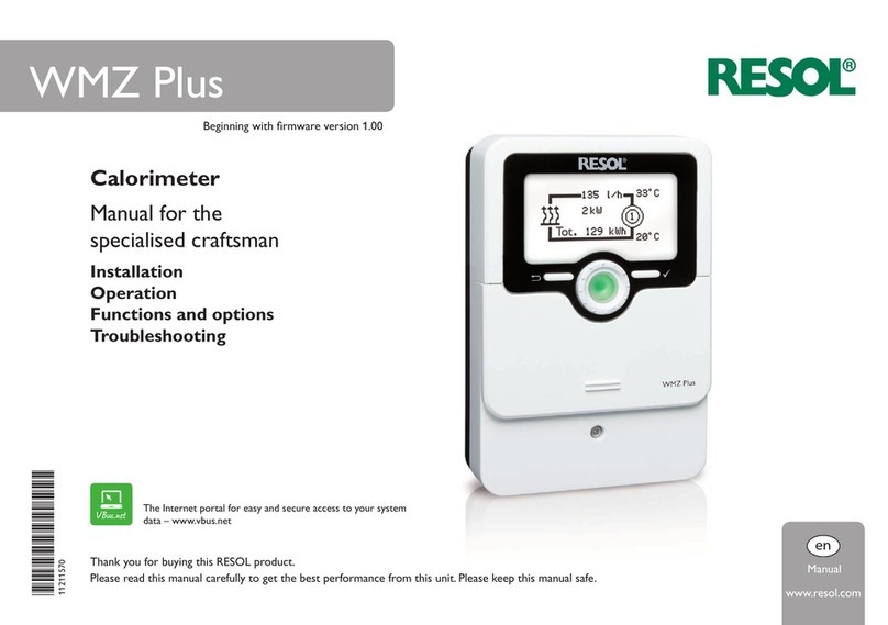
WMZ Plus
www.resol.com
Manual
en
Calorimeter
Manual for the
specialised craftsman
Installation
Operation
Functions and options
Troubleshooting
Thank you for buying this RESOL product.
Please read this manual carefully to get the best performance from this unit. Please keep this manual safe.
The Internet portal for easy and secure access to your
system data – www.vbus.net
Beginning with rmware version 1.01

2
en
© 20220407_11211576_WMZ_Plus.monen
Safety advice
Please pay attention to the following safety advice in order to avoid danger and
damage to people and property.
Danger of electric shock:
• When carrying out works, the device must rst of all be disconnected from the
mains.
• It must be possible to disconnect the device from the mains at any time.
• Do not use the device if it is visibly damaged!
The device must not be used by children or persons with reduced physical, sensory
or mental abilities or without any experience and knowledge. Make sure that child-
ren do not play with the device!
Only connect accessories authorised by the manufacturer to the device.
Make sure that the housing is properly closed before commissioning the device.
Set the code to the customer code before handing over the controller to the
customer.
Target group
These instructions are exclusively addressed to authorised skilled personnel.
Only qualied electricians are allowed to carry out electrical works.
Initial commissioning must be effected by authorised skilled personnel.
Authorised skilled personnel are persons who have theoretical knowledge and ex-
perience with the installation, commissioning, operation, maintenance, etc. of elec-
tric/electronic devices and hydraulic systems and who have knowledge of relevant
standards and directives.
Instructions
Attention must be paid to the valid local standards, regulations and directives!
Information about the product
Proper usage
The WMZ Plus is designed for measuring and indicating heat quantities in compli-
ance with the technical data specied in this manual.
Any use beyond this is considered improper.
Proper usage also includes compliance with the specications given in this manual.
The WMZ Plus is not suitable for billing purposes.
Improper use excludes all liability claims.
Note
Strong electromagnetic elds can impair the function of the device.
ÎMake sure the device as well as the system are not exposed to strong
electromagnetic elds.
EU Declaration of conformity
The product complies with the relevant directives and is therefore la-
belled with the CE mark.The Declaration of Conformity is available upon
request, please contact the manufacturer.
Scope of delivery
The scope of delivery of this product is indicated on the packaging label.
Storage and transport
Store the product at an ambient temperature of 0 … 40 °C and in dry interior
rooms only.
Transport the product in its original packaging only.
Cleaning
Clean the product with a dry cloth. Do not use aggressive cleaning uids.
Data security
We recommend regular backups of the data stored on the device via MicroSD card.
Subject to technical change. Errors excepted.

3
en
Decommissioning
1. Disconnect the device from the power supply.
2. Dismount the device.
Disposal
• Dispose of the packaging in an environmentally sound manner.
• At the end of its working life,the product must not be disposed of as urban waste.
Old appliances must be disposed of by an authorised body in an environmentally
sound manner. Upon request we will take back your old appliances bought from
us and guarantee an environmentally sound disposal of the devices.
Description of symbols
Warnings are indicated with a warning symbol!
Signal words describe the danger that may occur, when it is not avoided.
WARNING means that injury, possibly life-threatening injury, can occur.
ÎIt is indicated how to avoid the danger described.
ATTENTION means that damage to the appliance can occur.
ÎIt is indicated how to avoid the danger described.
Note
Notes are indicated with an information symbol.
ÎTexts marked with an arrow indicate one single instruction step to be carried
out.
1. Texts marked with numbers indicate several successive instruction steps to be
carried out.

4
en
WMZ Plus Calorimeter
Universal calorimeter module for solar, heating and cooling systems. Graphic display
for indication of ow and return temperature, heat quantity, ow rate and sensor
faults (balance values are also stored in case of a power failure). Suited for systems
with water or water-glycol mixtures (water, propylene glycol, ethylene glycol and
Tyfocor®LS adjustable).
The WMZ Plus meters the heat quantity as well as the cold quantity.The total en-
ergy results from the sum of heat and cold energy.
Contents
1 Overview ..............................................................................................5
2 Installation ...........................................................................................6
2.1 Mounting........................................................................................................................6
2.2 Electrical connection...................................................................................................7
2.3 Data communication / bus ..........................................................................................8
2.4 MicroSD card slot........................................................................................................9
3 Operation and function ......................................................................9
3.1 Buttons and adjustment dial......................................................................................9
3.2 Control lamp.................................................................................................................9
3.3 Parameterisation mode ............................................................................................10
3.4 Selecting menu points and adjusting values .........................................................10
3.5 Menu structure...........................................................................................................11
4 Flow rate sensors...............................................................................12
5 Commissioning..................................................................................13
6 Main menu .........................................................................................15
7 Status..................................................................................................15
7.1 Status ............................................................................................................................15
7.2 HQM.............................................................................................................................16
7.3 Service ..........................................................................................................................16
8 Balance values....................................................................................16
9 HQM ...................................................................................................17
10 Single and cascade operation...........................................................18
10.1 Single operation..........................................................................................................18
10.2 Cascade without controller.....................................................................................18
10.3 Cascade with controller...........................................................................................18
11 Basic settings .....................................................................................19
12 MicroSD card .....................................................................................19
13 User code ...........................................................................................20
14 Troubleshooting.................................................................................21
15 Index ...................................................................................................22

5
en
1 Overview
• Single or combined measurement of heat and cold energy
• Two independent calorimeters
• Commissioning menu for easy conguration
• Conversion into selectable alternative units (€, kg CO2, m³ gas, etc.)
Technical data
Inputs: 4 Pt1000 temperature sensors, 2 impulse inputs (adjustable), 2 4-20 mA
inputs (convertible to 0-10 V), 2 analogue Grundfos Direct SensorsTM (VFS)
Outputs: 2 S0 outputs
Power supply: 100 – 240 V~ (50 – 60 Hz)
Standby: < 1 W
Settings:
• Volumetric content of glycol: 0 … 70 % (1-% steps)
• Impulse rate of ow rate: 0 … 99 l/Imp (1-l/Imp steps) for V40 owmeter
Temperature measurement: with Pt1000 sensors and Grundfos Direct Sen-
sorsTM (VFS)
Measuring precision: ± 0.3 K
Measuring range: -40 … +120 °C (depending on the medium)
Data interface: VBus®, MicroSD card slot
VBus®current supply: 60 mA
Housing: plastic, PC-ABS and PMMA
Mounting: wall mounting, also suitable for mounting into patch panels
Indication / Display: graphic display, operating control LED (Lightwheel®)
Operation: 2 push buttons and 1 adjustment dial (Lightwheel®)
Ingress protection: IP 20 / EN 60529
Protection class: I
Ambient temperature: 0 … 40 °C
Fuse: T200mA
Maximum altitude: 2000 m above MSL
Dimensions: 110 x 166 x 47 mm
Application example
S2
S1

6
en
2 Installation
2.1 Mounting
WARNING! Electric shock!
Upon opening the housing, live parts are exposed!
ÎAlways disconnect the device from power supply
before opening the housing!
Note
Strong electromagnetic elds can impair the function of the device.
ÎMake sure the device as well as the system are not exposed to strong
electromagnetic elds.
The unit must only be located in dry interior rooms.
If the device is not equipped with a mains connection cable and a plug, the device
must additionally be supplied from a double pole switch with contact gap of at least
3 mm.
Please pay attention to separate routing of sensor cables and mains cables.
In order to mount the device to the wall, carry out the following steps:
1. Unscrew the crosshead screw from the cover and remove it along with the
cover from the housing.
2. Mark the upper fastening point on the wall. Drill and fasten the enclosed wall
plug and screw leaving the head protruding.
3. Hang the housing from the upper fastening point and mark the lower fastening
point (centres 130 mm).
4. Insert lower wall plug.
5. Fasten the housing to the wall with the lower fastening screws and tighten.
6. Carry out the electrical wiring in accordance with the terminal allocation (see
page 7).
7. Put the cover on the housing.
8. Attach with the fastening screw.
110
166
130
47
110 mm
20 mm
20 mm
166 mm
50 mm
150 mm
236 mm
Dimensions and minimum distances

7
en
2.2 Electrical connection
WARNING! Electric shock!
Upon opening the housing, live parts are exposed!
ÎAlways disconnect the device from power supply
before opening the housing!
ATTENTION! ESD damage!
Electrostatic discharge can lead to damage to electronic
components!
ÎTake care to discharge properly before touching the
inside of the device! To do so, touch a grounded sur-
face such as a radiator or tap!
Note
Connecting the device to the power supply must always be the last step
of the installation!
Note
It must be possible to disconnect the device from the mains at any time.
ÎInstall the mains plug so that it is accessible at any time.
ÎIf this is not possible, install a switch that can be accessed.
If the mains cable is damaged, it must be replaced by a special connection
cable which is available from the manufacturer or its customer service.
Do not use the device if it is visibly damaged!
Depending on the product version, mains cables and sensor cables are already con-
nected to the device. If that is not the case, please proceed as follows:
Attach exible cables to the housing with the enclosed strain relief and the corre-
sponding screws.
The stripped length of the cables must be at least 8 mm.
Connect the temperature sensors (S1 to S4) to the terminals S1 to S4 (either
polarity).
S1 = Sensor 1 (ow HQM 1)
S2 = Sensor 2 (return HQM 1)
S3 = Sensor 3 (ow HQM 2)
S4 = Sensor 4 (return HQM 2)
The cables carry low voltage and must not run together in a cable conduit with
cables carrying a voltage higher than 50 V (please pay attention to the valid local
regulations).The cable lentghs depend on the cross sectional area. Example: up to
100 m at 1.5 mm², up to 50 m at 0.75 mm². The cables can be extended with a
two-wire cable.
K1 and K2 are combined inputs for ow rate sensors.
The following table shows the terminal allocations for the different sensor types at
the combined inputs (K1 – WMZ 1 / K2 – WMZ 2):
Terminal GND
Sensor
ground
1
Flow rate
signal (fre-
quency)
2
Temperature
3
Flow rate
4
4-20 mA / 0-10 V
5
Power supply
5 V
Sensor
V40 ✓ ✓
VFS ✓ ✓ ✓ ✓
SIKA ✓ ✓ ✓
FlowRotor ✓ ✓ ✓
U / I ✓ ✓
US Echo II ✓ ✓ ✓
Connection examples
VBusS0 1
GND
S1 1 - +2 3 4 5
S2 K1
VBusS0 1
GND
S1 1 - +2 3 4 5
S2 K1 VBusS0 1
GND
S1 1 - +2 3 4 5
S2 K1 VBusS0 1
GND
S1 1 - +2 3 4 5
S2 K1
VBusS0 1
GND
S1 1 - +2 3 4 5
S2 K1 VBusS0 1
GND
S1 1 - +2 3 4 5
S2 K1
V40
either polarity
GND = green
2 = yellow
3 = white
5 = brown
GND
4
GND = black
1 = blue
5 = red
GND = brown
1 = green
5 = white
GND = blue
1 = black
5 = brown
VFS SIKA FlowRotor
U/I US Echo II
VBusS0 1
GND
S1 1 - +2 3 4 5
S2 K1
VBusS0 1
GND
S1 1 - +2 3 4 5
S2 K1
VBusS0 1
GND
S1 1 - +2 3 4 5
S2 K1 VBusS0 1
GND
S1 1 - +2 3 4 5
S2 K1
VBusS0 1
GND
S1 1 - +2 3 4 5
S2 K1 VBusS0 1
GND
S1 1 - +2 3 4 5
S2 K1
V40
either polarity
GND = green
2 = yellow
3 = white
5 = brown
GND
4
GND = black
1 = blue
5 = red
GND = brown
1 = green
5 = white
GND = blue
1 = black
5 = brown
VFS SIKA FlowRotor
U/I US Echo II

8
en
VBusS0 1
GND
S1 1 - +2 3 4 5
S2 K1 VBusS0 1
GND
S1 1 - +2 3 4 5
S2 K1
VBusS0 1
GND
S1 1 - +2 3 4 5
S2 K1
VBusS0 1
GND
S1 1 - +2 3 4 5
S2 K1
VBusS0 1
GND
S1 1 - +2 3 4 5
S2 K1 VBusS0 1
GND
S1 1 - +2 3 4 5
S2 K1
V40
either polarity GND = green
2 = yellow
3 = white
5 = brown
GND
4
GND = black
1 = blue
5 = red
GND = brown
1 = green
5 = white
GND = blue
1 = black
5 = brown
VFS SIKA FlowRotor
U/I US Echo II
VBusS0 1
GND
S1 1 - +2 3 4 5
S2 K1 VBusS0 1
GND
S1 1 - +2 3 4 5
S2 K1 VBusS0 1
GND
S1 1 - +2 3 4 5
S2 K1
VBusS0 1
GND
S1 1 - +2 3 4 5
S2 K1
VBusS0 1
GND
S1 1 - +2 3 4 5
S2 K1 VBusS0 1
GND
S1 1 - +2 3 4 5
S2 K1
V40
either polarity GND = green
2 = yellow
3 = white
5 = brown
GND
4
GND = black
1 = blue
5 = red
GND = brown
1 = green
5 = white
GND = blue
1 = black
5 = brown
VFS SIKA FlowRotor
U/I US Echo II
VBusS0 1
GND
S1 1 - +2 3 4 5
S2 K1 VBusS0 1
GND
S1 1 - +2 3 4 5
S2 K1 VBusS0 1
GND
S1 1 - +2 3 4 5
S2 K1 VBusS0 1
GND
S1 1 - +2 3 4 5
S2 K1
VBusS0 1
GND
S1 1 - +2 3 4 5
S2 K1
VBusS0 1
GND
S1 1 - +2 3 4 5
S2 K1
V40
either polarity GND = green
2 = yellow
3 = white
5 = brown
GND
4
GND = black
1 = blue
5 = red
GND = brown
1 = green
5 = white
GND = blue
1 = black
5 = brown
VFS SIKA FlowRotor
U/I
US Echo II
VBusS0 1
GND
S1 1 - +2 3 4 5
S2 K1 VBusS0 1
GND
S1 1 - +2 3 4 5
S2 K1 VBusS0 1
GND
S1 1 - +2 3 4 5
S2 K1 VBusS0 1
GND
S1 1 - +2 3 4 5
S2 K1
VBusS0 1
GND
S1 1 - +2 3 4 5
S2 K1
VBusS0 1
GND
S1 1 - +2 3 4 5
S2 K1
V40
either polarity GND = green
2 = yellow
3 = white
5 = brown
GND
4
GND = black
1 = blue
5 = red
GND = brown
1 = green
5 = white
GND = blue
1 = black
5 = brown
VFS SIKA FlowRotor
U/I
US Echo II
Note
If Grundfos Direct Sensors™ are used, connect GND of the combined
inputs (K1 / K2) to PE.
Note
Install the ow rate sensor into the return.
Connect the V40 owmeter to the terminals 1 and GND of the corresponding
combined input (either polarity).
The S0 outputs are used for issuing the energy quantity:
S0-1: HQM 1
S0-2: HQM 2
07.11.2019
1.120181212
1 : 1
WMZ Plus
T.Weber
Kundenfreigabe:Typenschilder
Customer approval:Type labels
FB055
Ident.-Bezeichnung Ident. designation
Herausgabeindex:
Issue index:
erteilt am:
Date of approval:
Änderungsindex:
Change index:
Art.-Nr.:
Art. no.:
Unterschrift:
Signature:
ja /yes nein /no
Name in Druckbuchstaben:
Name in block letters:
Kundenfreigabe Customer approval
Format:
Format:
RESOL-Basis-Art.-Nr.:
Basic RESOL art. no.:
Datum:
Date:
Bearbeiter:
Issuer:
Bemerkungen:
Remarks:
Urheberrecht / Copyright
Das Copyright für die von der Firma RESOL –Elektronische Regelungen GmbH selbst erstellten Objekte, Dokumente, Grafiken,Abbildungen,Tondoku-
mente,Videosequenzen,Texte etc.bleibt allein bei der Firma RESOL. EineVervielfältigung,Weitergabe an Dritte,Veränderung der Inhalte oder die Verwen-
dung in elektronischen oder gedruckten Publikationen ist ohne ausdrückliche Zustimmung der Firma RESOL nicht gestattet.
Please note that RESOL – Elektronische Regelungen GmbH owns the sole copyright on objects, documents, graphics, pictures, audio and video
documents, texts, etc. published and created by RESOL – Elektronische Regelungen GmbH. Copying, distribution to third parties, changing the contents
or using these contents in electronic or printed publications is not permitted without the explicit approval by RESOL.
Typenschild
Type label 1121155711211557
VBusS0 1
S0 2
GND
GND
WMZ Plus
Made in Germany
Sensors
S1
S3
1 - +
- +
2 3 4 5
1 2 3 4 5
100 - 240 V ~
T200mA
50 - 60 Hz
S2
S4 N L
IP 20
SD
K1
K2
The device is supplied with power via a mains cable.The power supply of the device
must be 100 – 240 V~ (50 – 60 Hz).
The mains connection is at the terminals:
Neutral conductor N
Conductor L
Protective earth conductor ⏚
Note
For more details about the commissioning procedure see page 13.
2.3 Data communication / bus
The device is equipped with a VBus®for data transfer and energy supply to ex-
ternal modules.The connection is to be carried out at the terminals marked VBus
(any polarity).
One or more VBus®modules can be connected via this data bus.
Note
If several VBus® accessories are used with a cascade, a VBus®-Repeater may
be required. For more information about cascade operation, see page 18.

9
en
2.4 MicroSD card slot
The device is equipped with a MicroSD card slot.
With a MicroSD card, the following functions can be carried out:
• Store measurement and balance values onto the MicroSD card.After the trans-
fer to a computer, the values can be opened and visualised, e.g. in a spreadsheet.
• Store adjustments and parameterisations on the MicroSD card and, if necessary,
retrieve them from there.
• Download rmware updates from the Internet and install them on the device via
MicroSD card.
MicroSD card slot
A MicroSD card is not included, but can be purchased from the manufacturer.
Note
For more information about using a MicroSD card, see page 19.
3 Operation and function
3.1 Buttons and adjustment dial
The device is operated via 2 buttons and 1 adjustment dial (Lightwheel®) below
the display:
Left button (⟲) - escape button for changing into the previous menu
Right button(✓) - conrming / selecting
Lightwheel®- scrolling upwards/ scrolling downwards, increasing adjust-
ment values / reducing adjustment values
3.2 Control lamp
The device is equipped with a multicolour LED in the centre of the Lightwheel®,
indicating the following states:
Colour Permanently shown Flashing
Green
Everything OK
Red
Sensor line break, sensor short circuit
Yellow
Parameterisation active, update in progress,
MicroSD card writing error

10
en
3.3 Parameterisation mode
After the installer code is entered (see page 20), the device changes to the pa-
rameterisation mode.
Note
In parameterisation mode, the metering process will stop and the message
Metering stopped – Parameterisation active will be indicated.
The LED in the Lightwheel®will glow yellow.
1. In order to carry out adjustments in the menu, press the right button (✓).
The device changes to the main menu in which adjustments on the installer level
can be made.
2. In order to save the adjustments made, select the menu item Save in the main
menu.
The device will leave the installer level and restart.
3.4 Selecting menu points and adjusting values
During normal operation of the device, the display indicates the main menu.
If no button is pressed for 2 min, the display illumination switches off.After another
2 min, the device changes to the status display.
ÎIn order to get from the status menu into the main menu, press the left button
(⟲)!
ÎPress any key to reactivate the display illumination.
ÎIn order to scroll through the menu items, turn the Lightwheel®.
If the symbol »is shown behind a menu item, pressing the right button (✓) will
open a new submenu.
Values and options can be changed in different ways:
Numeric values can be adjusted by means of a slide bar.The minimum value is indi-
cated to the left, the maximum value to the right.The large number above the slide
bar indicates the current adjustment.By turning the Lightwheel®, the upper slide bar
can be moved to the left or to the right.
Only after the adjustment has been conrmed by pressing the right button (✓) will
the number below the slide bar indicate the new value.The new value will be saved
if it is conrmed by pressing the right button (✓) again.
active areainactive area
When 2 values are locked against each other, they will display a reduced adjustment
range depending on the adjustment of the respective other value.
In this case, the active area of the slide bar is shortened, the inactive area is indicated
as a dotted line.The indication of the minimum and maximum values will adapt to
the reduction.
If only one item of several can be selected, they will be indicated with radio buttons.
When one item has been selected, the radio button in front of it is lled.

11
en
3.5 Menu structure
Main menu
Status
Balance values
HQM 1
HQM 2
Basic settings
SD card
User code HQM 1
Sen. ow rate
…
Fluid type
Concentration
Metering
Alternative unit
…
Status
HQM
Service
Messages
Version
The menu items and adjustment values selectable are variable depending on adjust-
ments already made. The gure only shows an exemplary excerpt of the complete
menu in order to visualise the menu structure.
Basic settings
Language
Date
Time
Auto DST
Vol. unit
Reset
If more than one item of several can be selected, they will be indicated with check-
boxes.When an item has been selected, an xappears inside the checkbox.
If further menu items are available and the symbol
is indicated on the upper
right-hand side of the display, more menu items can be accessed by turning the
Lightwheel®.

12
en
4 Flow rate sensors
The following ow rate sensor options are available:
• US Echo II
• SIKA
• U/I (sensors issuing voltage or current signals)
• FlowRotor
• VFS
• V40
Depending on the ow rate sensor selected further adjustment channels appear.
The following table gives an overview of the sensors and the corresponding ad-
justment values.
Flow rate
sensor
Corresponding
adjustment
channels
Description Adjustment
range / selection
Factory
setting
US Echo II US Echo II Impulse rate 0.1 … 100.0 l/Imp 1.0 l/Imp
SIKA SIKA Type VY1030M,
VY1030K, VTY20 VTY20
U/I
U/I Voltage or current signal 4-20 mA, 0-10 V 0-10 V
Curve Curve submenu
Unit Flow rate unit m³/h, l/min l/min
Volt 1 Voltage minimum ow rate (only
if 0-10 V has been selected) 0.0 … 10.0 V 1.0 V
Current 1 Current minimum ow rate (only
if 4-20 mA has been selected) 0 … 20 mA 4 mA
Fl.r.1 Minimum ow rate 0.0 … 500.0 l/min
0.0 … 30.0 m³/h
1.0 l/min
1.0 m³/h
Volt 2 Voltage maximum ow rate (only
if 0-10 V has been selected) 0.0 … 10.0 V 10.0 V
Current 2 Current maximum ow rate (only
if 4-20 mA has been selected) 0 … 20 mA 20 mA
Fl.r.2 Maximum ow rate 0.0 … 500.0 l/min
0.0 … 30.0 m³/h
10.0 l/min
10.0 m³/h
FlowRotor FlowRotor Type DN20, DN25,
DN32 DN20
VFS VFS Type 2-40, 1-12 2-40
V40 V40 Impulse rate 0.1 … 100.0 l/Imp 1.0 l/Imp
The characteristic curve of the voltage and current signal as a function of the ow
rate is dened by 2 set points. At a ow rate of Fl.r.1 the voltage signal is Volt 1 and
the current signal Current 1 respectively. At a ow rate of Fl.r.2 the voltage signal
is Volt 2 and the current signal Current 2 respectively. The device automatically
calculates the characteristic curve resulting from these values.
Note
The ow rate sensor has to be installed in the return.
Voltage signal in V / Current signal in mA
Flow rate in l/min

13
en
5 Commissioning
When the system is ready for operation, establish power supply of the device.
The device runs an initialisation phase in which the Lightwheel®glows red.
When the device is commissioned or when it is reset, it will run a commissioning
menu after the initialisation phase.The commissioning menu leads the user through
the most important adjustment channels.
Commissioning menu
The commissioning menu consists of the channels described in the following. In
order to make an adjustment, adjust the desired value with the Lightwheel®and
conrm with the right button (✓).The next channel will appear in the display.
Adjustment mode
Operation
Changing a value
Conrming a value
Next parameter
1. Language:
ÎAdjust the desired menu language.
2. Daylight savings time adjustment:
ÎActivate or deactivate the automatic daylight sav-
ings time adjustment.
3. Time:
ÎAdjust the clock time. First of all adjust the hours,
then the minutes.
4. Date:
ÎAdjust the date. First of all adjust the year, then the
month and then the day.
5. Cascade:
ÎIf the device is to be used in a cascade, select Ye s .
6. Bus mode (if 5. = Yes):
ÎDene whether the device is used as a master
with a controller, as a master or as a slave.

14
en
7. Flow rate sensor:
ÎAdjust the desired ow rate sensor.
Depending on the ow rate sensor selected further
adjustment channels appears, see page 12.
8. Medium:
1. Adjust the desired heat transfer uid.
If Tyfocor LS, Ethyl or Propyl. has been selected,
another channel for adjusting the antifreeze concen-
tration appears.
2. Adjust the desired concentration of the heat
transfer medium.
10. Alternative unit:
1. Activate or deactivate the alternative unit.
If the alternative unit is activated,further channels appear:
2. Adjust the desired Unit.
3. Adjust the desired Factor.
9. Metering:
ÎAdjust the desired energy metering.
11. Second HQM?
ÎActivate a second heat quantity measurement, if
required.
Note
If a second calorimeter is activated, the chan-
nels described above will be displayed for the
second heat quantity measurement.
12. Completing the commissioning menu:
After the adjustments have been made, a security en-
quiry appears. If the security enquiry is conrmed, the
adjustments will be saved.
ÎIn order to conrm the security enquiry, press the
right button (✓).
ÎIn order to get back to the adjustment channels of
the commissioning menu,press the left button (⟲).
After the security enquiry has been conrmed, the de-
vice is ready for operation.
Note
The adjustments carried out during commis-
sioning can be changed anytime in the corre-
sponding adjustment channel.Additional func-
tions and options can also be activated and
adjusted.

15
en
7 Status
The status menu is divided into the menu areas Status, HQM and Service.
7.1 Status
In the Status / Status menu, all current measured values are indicated in a clear
graphic. Each HQM has its own display. In order to change between HQM 1 and
HQM 2, turn the Lightwheel®.
The information given in the graphic can also be indicated as a text. For this pur-
pose, select the desired HQM and press the right button (✓). In order to get back
to the graphic, press the left button (⟲).
Symbol Description
HQM 1
HQM 2
Heat generator (if heat quantity is metered)
Cold generator (if cold quantity is metered)
6 Main menu
In this menu, different menu areas can be selected.
The following menus are available:
• Status
• Balance values
• HQM 1
• HQM 2
• Basic settings
• SD card
• User code
1. Select the menu area by turning the Lightwheel®.
2. In order to access the desired menu area, press the right button (✓).
During normal operation of the device, the display indicates the main menu.
If no button is pressed for 2 min, the display illumination switches off.After another
2 min, the device changes to the status display.
ÎIn order to get from the status menu into the main menu, press the left button
(⟲)!

16
en
7.2 HQM
In the Status / HQM menu, the submenus HQM 1 and HQM 2 can be found in
which all current measured values of the ow and return sensors, ow rate and
power as well as heat quantity of the corresponding calorimeter are indicated.
7.3 Service
In the Status / Service menu, the Messages submenu can be found in which er-
ror and warning messages are indicated.
During normal operation, the message Everything OK is indicated.
In case of an error message, the display indicates the error type.
After the error has been removed, the error message will disappear.
Display Description
HQM 1
!Fl. def.
HQM 1
Flow sensor defective (short-circuit or
line break)
HQM 1
!Ret. def.
HQM 1
Return sensor defective (short-circuit
or line break)
HQM 2
!Fl. def.
HQM 2
Flow sensor defective (short-circuit or
line break)
HQM 2
!Ret. def.
HQM 2
Return sensor defective (short-circuit
or line break)
!Date/Time Clock module failed
!Data storage def. Data storage defective
Card full SD card full
Metering stopped
Parameterisation mode active
8 Balance values
In the Balance values menu, all balance values of the corresponding calorimeter
are indicated. If, for example, HQM 1 is selected, a submenu indicating all current
values of the rst calorimeter opens.

17
en
9 HQM
In the HQM 1 and HQM 2 menus, up to 2 internal heat quantity measurements
can be activated and adjusted.
HQM 1 and HQM 2 respectively
Adjustment
channel Description Adjustment range/selection Factory
setting
Sen. ow rate Flow rate sensor selection US Echo II, SIKA, U/I, FlowRo-
tor, VFS, V40 -
US Echo II Impuls rate 0.1 … 100.0 l/Imp 1.0 l/Imp
SIKA Type VY1030M, VY1030K, VTY20 VTY20
U/I Voltage or current signal 4-20 mA, 0-10 V 0-10 V
Curve Curve submenu
Unit Flow rate unit m³/h, l/min l/min
Volt 1 Voltage minimum ow rate (only if
0-10 V has been selected) 0.0 … 10.0 V 1.0 V
Current 1 Current minimum ow rate (only
if 4-20 mA has been selected) 0 … 20 mA 4 mA
Fl.r.1 Minimum ow rate 0.0 … 500.0 l/min
0.0 … 30.0 m³/h
1.0 l/min
1.0 m³/h
Volt 2 Voltage maximum ow rate (only
if 0-10 V has been selected) 0.0 … 10.0 V 10.0 V
Current 2 Current maximum ow rate (only
if 4-20 mA has been selected) 0 … 20 mA 20 mA
Fl.r.2 Maximum ow rate 0.0 … 500.0 l/min
0.0 … 30.0 m³/h
10.0 l/min
10.0 m³/h
FlowRotor Type DN20, DN25, DN32 DN20
VFS Type 2-40, 1-12 2-40
V40 Impuls rate 0.1 … 100.0 l/Imp 1.0 l/Imp
Fluid type Heat transfer uid Tyfocor LS, Ethyl., Propyl.,Water Water
Concentr.
Glycol concentration in the heat
transfer uid (only if uid type =
propylene glycol or ethylene glycol)
20 … 70 % 40 %
Adjustment
channel Description Adjustment range/selection Factory
setting
Metering Selection of quantity to be metered Combined, Heat, Cold Heat
Alternative unit Alternative unit option Yes, No No
Unit Alternative display unit Coal, Gas, Oil, CO2, €CO2
Factor Conversion factor 0.0000001 … 100.0000000 0.5000000
S0 output Switch input selection - -
Duration Impulse duration 30 … 120 ms 100 ms
Break Impulse break 30 … 120 ms 30 ms
Imp/kWh Impulse rate 1 … 1000 100
Reset back to factory setting Yes, No No
Funct. Activation / Deactivation Activated, Deactivated Activated
S1 is the ow sensor, S2 is the return sensor. If VFS has been selected as the ow
rate sensor, the return temperature is measured automatically via the VFS sensor.
In this case, the return sensor can be changed with the Sen. return parameter.
Depending on the ow rate sensor selected further adjustment channels appear,
see page 12.
In the adjustment channel Fluid type the heat transfer uid must be selected.
If either propylene glycol or ethylene glycol is selected, the adjustment channel
Concentration is indicated in which the antifreeze ratio of the heat transfer uid
can be adjusted.
For temperatures below 0 °C a heat transfer uid with antifreeze is to be used.
The Metering channel is used for selecting whether heat quantity, cold quantity or
both are to be metered.
When the Alternative unit option is activated, the device will convert the en-
ergy quantities into the quantity of fossil fuels (coal, oil or gas) saved, or the CO2
emission saved respectively.The alternative Unit can be selected.A factor must be
adjusted for the calculation.The conversion factor depends on the arrangement in
use and has to be determined individually.
In the S0 output menu, a digital impulse output can be adjusted for each calorim-
eter, in order to issue the energy metered in form of pulses.The impulse duration,
break and rate can be adjusted.
In order to reset the settings of a calorimeter, select Reset and conrm the secu-
rity enquiry with Ye s .
With the menu item Function, a calorimeter already adjusted can be temporarily
deactivated or re-activated respectively. In this case, all adjustments will remain
stored. If a calorimeter is deactivated, energy metering does not take place by this
one. Sensor faults are ignored for the deactivated HQM.

18
en
10 Single and cascade operation
The WMZ Plus can be used as a single device or in a cascade. Up to 8 WMZ Plus
can meter 16 heat quantities in total. If several WMZ Plus are used, the master has
to be adjusted rst.
The following possibilities are available:
10.1 Single operation
In single operation, one WMZ Plus can be connected to VBus®accessories.
Adjustment WMZ Plus:
Cascade = No; Bus mode = Single
10.2 Cascade without controller
In cascade operation, several WMZ Plus can be connected to each other via the
VBus®.
Adjustment WMZ Plus 1:
Cascade = Yes; Bus mode = Master
Adjustment WMZ Plus 2 to 8:
Cascade = Yes; Bus mode = Slave 1 … 7
10.3 Cascade with controller
In cascade mode, one or severeal WMZ Plus can be conneted to one controller
via the VBus®.
Adjustment WMZ Plus 1:
Cascade = Yes; Bus mode = M.+C.
Adjustment WMZ Plus 2 to 8:
Cascade = Yes; Bus mode = Slave 1 … 7
1
1
1
2
2
3
3
4
4
8
8

19
en
In the Basic settings menu, all basic parameters for the device can be adjusted.
Normally, these settings have been made during commissioning.They can be subse-
quently changed in this menu.
Basic settings
Adjustment channel Description Adjustment range / selection Factory setting
Language Selection of the menu language Deutsch, English, Français,
Español, Italiano
Deutsch
Date Adjustment of the date 01.01.2001 … 31.12.2099 01.01.2012
Time Adjustment of the current
time
00:00 … 23:59 -
Auto DST
Daylight savings time selection
Yes, No Ye s
Flow unit Volume unit l, m³ l
Bus mode Bus mode single/ cascade op-
eration
M.+C., Master, Slave 1 … 7 -
Reset back to factory setting Yes, No No
11 Basic settings 12 MicroSD card
SD card
Adjustment channel Description Adjustment range / selection Factory setting
Rem. time Remaining logging time - -
Remove card... Safely remove card - -
Save adjustments Save adjustments - -
Load adjustments Load adjustments - -
Logging int. Interval for data logging 00:01 … 20:00 (mm:ss) 60:00
Logging type Logging type Cyclic, Linear Linear
The device is equipped with a MicroSD card slot for MicroSD memory cards.
With a MicroSD card, the following functions can be carried out:
• Logging measurement and balance values. After the transfer to a computer, the
values can be opened and visualised, e.g. in a spreadsheet.
• Store adjustments and parameterisations on the MicroSD card and, if necessary,
retrieve them from there.
• Running rmware updates on the device.
Firmware updates
The current software can be downloaded from www.resol.de/rmware. When a
MicroSD card with a rmware update is inserted, the enquiry Update? is indicated
on the display.
ÎIn order to run an update, select Ye s and conrm with the right button (✓).
The update will run automatically.The indication Please wait and a progress bar
appear on the display. When the update has been completed, the device will auto-
matically reboot and run a short initialisation phase.
Note
Only remove the card when the initialisation phase has been completed
and the main menu is indicated on the device display!

20
en
ÎTo skip the update, select No.
The devices starts normal operation.
Note
The device will only recognise a rmware update le if it is stored in a
folder named RESOL\WMZ on the rst level of the MicroSD card.
ÎCreate a folder named RESOL\WMZ on the MicroSD card and ex-
tract the downloaded ZIP le into this folder.
Starting the logging
1. Insert the MicroSD card into the slot.
2. Adjust the desired logging type and interval.
Logging will start immediately.
Completing the logging process
1. Select the menu item Remove card...
2. After Remove card is displayed, remove the card from the slot.
When Linear is adjusted in the logging type adjustment channel, data logging will
stop if the capacity limit is reached.The message Card full will be displayed.
If Cyclic is adjusted, the oldest data logged onto the SD card will be overwritten as
soon as the capacity limit is reached.
Note
Because of the increasing size of the data packets, the remaining logging
time does not decrease linearly. The data packet size can increase, e.g. with
the increasing operating hours value.
Saving adjustments
ÎTo store the adjustments on the MicroSD card, select the menu item Save
adjustments.
While the adjustments are being stored, rst Please wait, then Done! will be indi-
cated on the display. The adjustments are stored as a .SET le on the MicroSD card.
Loading adjustments
1. To load adjustments from a MicroSD card, select the menu item Load ad-
justments.
The File selection window will appear.
2. Select the desired .SET le.
While the adjustments are being loaded, rst Please wait, then Done! will be
indicated on the display.
Note
To safely remove the MicroSD card, always select the menu item Remove
card…before removing the card.
13 User code
In the User code menu, a user code can be entered. Each number of the 4-digit
code must be individually adjusted and conrmed. After the last digit has been con-
rmed, the menu automatically jumps to the superior menu level.
To access the menu areas of the installer level, the installer user code must be
entered:
Installer: 0262
If the installer user code has been entered, the device changes to the parameteri-
sation mode, see page 10.
Note
For safety reasons, the user code should generally be set to the customer
code before the device is handed to the customer!
Customer: 0000
If a parameter of the installer level is to be changed without previously having en-
tered the user code, the user code enquiry appears. Only if the installer user code
has been entered, can the parameter be changed.
Other manuals for WMZ Plus
1
Table of contents
Other Resol Measuring Instrument manuals

Resol
Resol WMZ-M1 User manual

Resol
Resol DL3 How to use

Resol
Resol V40 User manual

Resol
Resol WMZ-G1 User manual

Resol
Resol WMZ Plus User manual

Resol
Resol WMZ-G1 Instruction manual

Resol
Resol FlowCon B User manual

Resol
Resol VM1020 Service manual

Resol
Resol WMZ User manual

Resol
Resol DFA comfort User manual