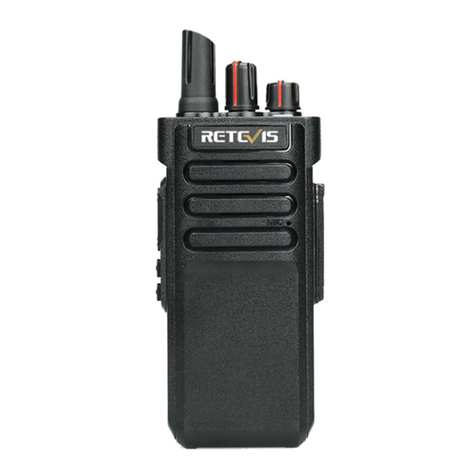
Retevis RA685 User manual

User’s manual
RA685

EU Importer: Germany Retevis Technology GmbH
Address: Uetzenacker 29,38176 wendeburg
For downloading further resources:
Brochures, Software/Firmware, Manual etc, Pls contact your direct reseller first OR go
to website retevis.com and check “support” in the each product link to download it.

Menu
FEATURE.................................................................................
Check the contents of the package.......................................
Familiar with this machine.....................................................
Status indication.....................................................................
LED indicator light..................................................................
Preparation before use...........................................................
Walkie-talkie charging............................................................
Basic operation.......................................................................
Function Description..............................................................
Common function description...............................................
Voice-activated emission (VOX)............................................
Channel storage......................................................................
Analog sub-audio (CTCSS)/digital sub-audio (CDCSS)......
Main Specifications................................................................
DE(16-31)
FR(32-47)
IT(48-63)
ES(64-79)
1
1
1
2
2
2
3
4
5
8
8
9
10
11

Antenna
Flashlight
Power on
/Volume button
Display
Loud speaker
TX/RX
indicator light
MIC
Keyboard
button
1
FEATURE
1. Frequency range: 144-146MHZ(RX/TX) 430-440MHZ(RX/TX)
2. Dual band, Dual Display, Dual Standby, U/V band relay cross-band transmission and reception, convenient for
users to set network at any time.
3. High, middle, and low power switching to meet the power requirements of users at different distances, more
energy-saving and power-saving
4. Up to 128 memory channels for programming frequency and other various data
5. Multiple display modes such as channel number, frequency, channel frequency, channel name, etc.
6. CTCSS/DCS, DTMF signaling, reject redundant calls from other stations
7. The tail tone is eliminated to avoid the impact noise from the speaker after the call is over
8. VOX voice-activated transmission, no need to press the PTT button to talk normally
9. Emergency alarm, ANI identification and other functions through DTMF
10. DTMF, CTCSS (60.0 -259.9 HZ), DCS signaling codec function
11. 8 step frequency selection (2.5K, 5.0K, 6.25K, 10.0K, 12.5K, 20.0K, 25.0K, 50.0K)
12. Automatic power saving function to extend battery life
13. SOS emergency alert function
14. Computer programming function
15. Wide/narrow band (25KHz/12.5KHz) selection function
16. Digital FM radio (receiving 65-108MHz)
17. Direct selection of keyboard numbers for menu items, the transmit and receive frequency can be manually
input
18. Strong flashlight lighting function
19. Frequency test function , copy the frequency of other devices at any time
20. USB charging function, you can use the USB charging cable to charge
21. Special CTCSS/DCS (frequency hopping function)
Check the contents of the package
The box contains the following items. If any items are missing or damaged, please contact the dealer where you
purchased the product.
Note: The antenna varies with the frequency band. Please refer to the color ring label at the bottom of the
antenna for the antenna frequency band. If the label does not indicate the frequency band, please refer to the
specific frequency band on the host label.
Familiar with this machine
Parts introduction
Article Quantity Article Quantity
Host 1 Charging base 1
Battery 1 Belt clip 1
Antenna 1 Manual 1
Sling 1
PTT Earpiece
jack
USB charging
port
Side Key1
Side Key2

2
Status indication
Status Icons
LED indicator light
This machine is equipped with LED indicators to let you
easily grasp the current operating status of the machine.
Preparation before use
Install the antenna
1. Turn off the walkie-talkie and insert the threaded end of the antenna
into the antenna port on the top of the main unit.
2. Tighten the antenna clockwise.
When removing the antenna, rotate it counterclockwise to remove it.
Do not shake the unit with the top of the antenna, otherwise it will reduce
the working performance and service life of the unit's antenna.
No. Icon Product Status
1 Channel strength indicator, the more the number, the stronger the signal
The current transmitting power is high power (the longest communication distance,
the largest power consumption);
2 The current transmitting power is medium power (more power saving, relatively moderate
communication distance);
The current transmitting power is low power (the most power saving, relatively close distance)
3 When the side tone switch is set to key side tone/key + ID/ID, this symbol appears
4 This symbol indicates that the current subtone is a digital subtone
This symbol indicates that the current subtone is an analog subtone
When this symbol appears in frequency mode, it means that the transmitting frequency is the
receiving frequency plus a frequency difference frequency. The frequency difference
5 frequency is set in menu 26
When this symbol appears in frequency mode, it means that the transmitting frequency is the
receiving frequency minus a frequency difference frequency. The frequency difference
frequency is set in menu 26
The appearance of this symbol indicates that the dual-band standby is on, and it is in the
6 dual-standby state. It can be watched at the frequency points of the two frequency bands
displayed on the screen
7 The symbol appears when the keyboard is locked; press and hold the [#] key to unlock, and
the symbol disappears
8 Indicates that the voice-activated emission function is activated, and the emission will start
when the sound pressure level of the microphone reaches the set value
9 Receiving and transmitting frequency inversion in frequency mode/channel mode
10 This symbol appears when the channel is working in narrowband mode
11 Display the current remaining battery power; the more bars, the more battery power
12 A/B band pointer, indicating the current working frequency or working channel
13 Aranbic No. Digital channel mode, the channel number of the A band
14 Aranbic No. Digital In channel mode, the channel number of the B band
Indicator status Native status
Steady Red light Launching
Steady green light Receiving

3
Install the battery
1. Align the battery with the battery mount on the back of the walkie-talkie.
2. Press the battery forcefully into the walkie-talkie, and slide the battery up until the lock plate is locked to the
correct position.
If you need to remove the battery, turn off the walkie-talkie. Press the battery lock to the unlocked position and
hold it down, then slide the battery down and away from the battery mount.
Install the belt clip
Align the two screw holes of the belt clip with the screw holes above the
battery, install and tighten the screws.
If you need to remove the belt clip, loosen and remove the screws from
the belt clip.
Install an external headset/microphone (optional purchase separately)
1.Open the earphone cover.
2. Insert the headphone plug into the headphone jack.
When you don't need to use the earphones, pull out the earphone plug from the earphone
hole and put on the earphone cover. When the universal interface is not used, please put
on the dust cover.
Attention:
• Please use the charging equipment designated by our company to charge.
When charging the whole device, it is recommended to turn off the walkie-talkie first.
•According to the 2016 new requirements of the International Civil Aviation (IATA) "Technical
Regulations for the Safe Air Transport of Dangerous Goods", the state of charge of lithium-ion batteries (cells) for
air transport shall not exceed 30% of their rated capacity. Therefore, the first time the battery is used with the
host, there will be a low battery warning with the voice prompt "please charge". Phenomenon, please charge the
battery before use.
• When the battery is charged in the charger, the red light may keep flashing. This is the pre-charging process
performed by the charger to protect the battery when the battery power is too low. It is a normal phenomenon.
Generally, it can turn to red after 30 seconds. Normal charging state when the light is on.
Walkie-talkie charging
When using the terminal for the first time, a low battery alarm may appear. Please charge the battery before
using the terminal, the steps are as follows:
1. Insert the power adapter interface into the jack on the back of the charging base.
2. Insert the plug of the power adapter into the power outlet.
3. Put the battery into the charging cradle.
4. Observe the LED indicator of the charging base to understand the current charging status, as shown in the
table below.
Check battery
This function allows you to know the current battery voltage and remaining power.
Long press【0】key to display the current voltage.
The current battery level is displayed on the upper right of the screen, and the battery icon is as follows:
The charging indicator light shows The current charging status
Red light flashes Battery voltage is too low
Red light is on Charging
Green light is on Charging is complete
Battery Icon Batter Power
High
Middle
Low
insufficient

4
Basic operation
Knobs, switches, Instructions
buttons
Power/volume •Power on/off: Turn the [Power/Volume Switch] knob clockwise to turn on the radio and adjust
switch the volume to the maximum.
•Turn the [Power/Volume Switch] knob counterclockwise to adjust the volume to the minimum
until the radio is turned off.
•If the voice broadcast function is turned on, the startup voice will be broadcast.
Select channel The channel is the channel through which the signal is transmitted. After power on, press the
[V/M] key to switch to the channel mode, press [/] to select the channel, and the channel
number will be displayed on the right side of the screen. If the channel broadcast function is
turned on, the intercom will broadcast the current channel mode.
PTT button call •Channel mode to initiate a call: After selecting a channel, press and hold the [PTT] key to
initiate a call to the current channel. Speak into the microphone in a normal tone. When a call
is initiated, the red LED light is always on.
•Manually input frequency to initiate a call: Press [V/M] key to switch to frequency mode, enter
a frequency within the allowable range, and hold down the [PTT] key to initiate a call to the
current channel. Speak into the microphone in a normal tone. When a call is initiated, the red
LED light is always on.
•Receiving a call: After releasing the [PTT] key, you can answer it without any operation.When
receiving a call, the green LED light is always on.To ensure the best receiving volume, please
keep the distance between the microphone and your mouth at 2.5 cm ~ 5 cm when transmitting.
Side Key 1 The side buttons have two modes: short press and long press, and the following functions can
be selected: off, flashlight, alarm, radio, NOAA weather forecast, monitoring, and scan.
Off: No function
Flashlight function: Short press the [SK1] key to turn on the flashlight function and the flashli-
ght light is always on; short press the [SK1] key again to turn off the flashlight function. If you
choose to operate the flashlight function in the menu mode,short press the [SK1] key to turn
on the flashlight for the first time, short press the second flashlight to keep flashing, and short
press three times to turn off the flashlight.
Alarm: SOS emergency alarm function: Short press the [SK1] key to turn on the alarm function.
At this time, the green indicator light and the red indicator light flash at the same time. Short
press the [SK1] key again to release the alarm.
Radio: Short press the [SK1] key to turn on the radio function, and short press the [SK1] key
again to turn off the radio.The radio frequency can be entered through the keyboard or tap
the "#" key to automatically search for radio stations. In radio mode, press the [EXIT] key to
switch between 65-75/76-108MHz frequency band.
NOAA weather forecast: Short press the [SK1] key to turn on the NOAA function, and short
press the [SK1] key again to turn off the NOAA function.
Press the up and down keys to select the channel: 10 channels for selection: see Appendix
1 for details
Monitoring function: Short press the [SK1] key to turn on the monitoring function, and release
the [SK1] key to cancel the monitoring.
Sweep: Short press [SK1] key to turn on the sweep function, and directly measure the
frequency of other devices.
5
Function Description
Menu Settings
You can enter "Menu Settings" through the menu key of the terminal to set some common functions. The specific
instructions and operation methods are as follows:
Side Key 2 The same side key SK1 has a short press and long press function to choose
V/M key Frequency mode or channel mode switching.
•Frequency mode: Manually enter the frequency.
Channel mode: Press [ ▲ / ▼ ]to select a channel.
A/B key A/B upper and lower frequency band switch selection.
Press the PTT button to transmit in the frequency band pointed to by the pointer.
Keyboard lock Manual lock: Long press # key to lock the intercom.
and unlock Automatic lock: After the automatic keyboard lock is turned on, when there is no operation
on the buttons and knobs,the automatic lock will be delayed for 10 seconds.
Unlock: Long press the # key to unlock the keyboard.
Menu First-level menu Secondary menu Description of secondary menu setting
number display characters display characters
0 Squelch 0,…,9 Squelch level, the lower the level, the easier it is to interfere,
the higher the level the worse the sensitivity, the default value
is 3.
1 Step 2.5KHz In frequency mode, press ▲ / ▼ key to change the step value
5.0KHz of frequency, the value range is 2.5~50KHz
6.25KHz
10.00KHz
12.50KHz
20.0KHz
25.0KHz
50.0KHz
2 Tx Power High High power
Middle Middle Power
Low Low Power
3 Power save OFF Turn off power saving mode
ON Turn on power saving mode
4 Vox Level OFF Turn off voice control
1,2,… 10 Start the sound control level intensity, value range
5 Bandwidth Wide Wide band working
Narrow Narrow band working
6 Backlight Bright Backlight is always on
5Sec,10Sec,… 60Sec Automatic backlight delay time, the value range is 5~60 seconds
7 Menu Exit Time 5Sec,10Sec,… 60Sec Menu exit time, the value range is 5~60 seconds
8 Dual Standby OFF OFF
ON ON
9 Beep Prompt OFF OFF
ON ON
10 VOICE OFF OFF
ON ON

6
11 Tx over time OFF Press and hold the PTT button to keep launching
15,30,…600 Value range 15~600, step value 15
12 Rx DCS OFF NO DCS
D023N,…,D754I Standard sequence of DCS
13 Rx CTCSS OFF NO CTCSS
67.0HZ,…,254.1HZ Simulate the standard sequence of mute, at the same time,
you can directly type standard or non-standard analog mute
through the keyboard
14 Tx DCS OFF NO DCS
D023N,…,D754I Standard sequence of DCS
15 Tx CTCSS OFF NO CTCSS
67.0HZ,…,254.1HZ Simulate the standard sequence of mute, at the same time,
you can directly type standard or non-standard analog mute
through the keyboard
16 DTMFST OFF OFF
DT-ST DT-ST
ANI-ST ANI-ST
DT+ANI DT+ANI
17 TONE 1000hz,1450hz, Repeater activation audio
1750hz,2100hz
18 S-CODE 1,2,…,15 When needed, send out this group of information codes
g (information codes can only be written by frequency writing
software)
19 Scan Mode TO Time Scan
CO Carrier Scan
SE Search Scan
20 PTT-ID OFF Press PTT to not send ID code
BOT Press PTT to send ID code (ID code is set by frequency
writing software)
EOT Release PTT to send ID code
BOTH ID code is sent when you press and release the PTT button
21 MDF-A Frequency In the channel mode of the A segment, the channel displays
the frequency
Name In the channel mode of section A, the channel displays the
channel name (the specific name is set in the frequency
writing software)
22 MDF-B Frequency Band B is in channel mode, the channel displays the frequency
Name In the channel mode of section B, the channel displays the
channel name (the specific name is set in the frequency
writing software)
23 Busy Lockout OFF Channel is occupied and allowed to transmit
ON Channel is occupied and transmission is prohibited
24 Key Auto Lock OFF Turn off automatic keyboard lock
ON Turn on the keyboard auto-lock function
25 Direction None In frequency mode, there is no frequency difference between
the transmitting frequency and the receiving frequency

7
25 Direction Plus In frequency mode, the transmitting frequency is equal to the
receiving frequency plus the frequency difference frequency
Minus In frequency mode, the transmitting frequency is equal to the
receiving frequency minus the frequency difference frequency
26 Offset 00.000,…,99.998 In frequency mode, the difference between the transmitting
and receiving frequencies
27 Key1 sp OFF No function
LAMP Turn on the flashlight function
SOS Turn on the alarm function
FM Turn on the radio function
NOAA Enable NOAA weather forecast function
MONI Turn on the monitoring function
Scan Turn on the sweep function
28 Key1 LP Same function as side key 1 short press
29 Key2 sp Same function as side key 1 short press
30 Key2 LP Same function as side key 1 short press
31 Memory 1,…,128 When storing a channel, it is used to indicate the channel
number to be stored. If the word CH- is displayed in front of
the number, it means that the channel originally has channel
parameters
32 Delete 1,…,128 Delete the channel parameters of the specified channel, if
there is no CH- in front, it means that the channel has no
parameters and the operation is invalid
33 Alarm Mode On site On-site alarm
Send sound Send sound
Send code Send code
34 TAIL OFF After the PTT is released, the machine does not send a
shutdown code, usually when it is relayed through the relay,
let it make noise to confirm whether the signal of the
machine is relayed
ON After releasing the PTT button, the machine sends a shutd-
own code to suppress the instantaneous noise of the listener
35 PROGER OFF Turn off the call end alert tone
ON Turn on the call end alert tone
36 Language Chinese
English
37 Reset VFO Menu initialization only
ALL Menu and channel initialization
38 SPECIAL DCS OFF Close special DCS
ON Open Menu and channel initialization, only with same DCS
can communicate

8
Common function description
The functions supported by the walkie-talkie are shown in the table below.
Name Function description
Squelch level Squelch level adjustment Squelch level adjustment is to adjust the signal strength required when
adjustment receiving a signal. The squelch level (0 open to 9 is the highest) is selected by the local environ-
ment, and 3 is generally selected.
CTCSS/DCS CTCSS/DCS is used to avoid listening to irrelevant calls of the same frequency. Only when the
transmitted CTCSS/DCS matches the received CTCSS/DCS digital, the walkie-talkie can listen
to the voice through the speaker.
TOT Timeout prohibition TOT timeout prohibition can limit the single transmission time (the default is
60 seconds) to prevent the communication parties from occupying channel resources for a long
time, and to prevent the terminal from being damaged due to overheating. After the duration of
pressing the [PTT] key expires, the terminal will automatically terminate the transmission and
emit a warning tone. If you need to talk again, please transmit after the preset time.
Power saving When the walkie-talkie has no receiving or transmitting, no button or knob operation reaches the
power saving time, it will automatically enter the power saving mode.
Low battery It is used to remind the battery to charge in time when the battery power is low. When the battery
warning is too low, transmission will be prohibited.
Emergency An emergency alarm is when you encounter an emergency, you can ask your companion or the
Alarm control center for help.
SCAN After scanning is turned on, the terminal will scan according to the scan list. When there is
activity on a certain channel, it will stay on the channel to listen, so as to understand the current
activity status of related group members.
BCL Busy channel lock BCL can prevent interference from other terminals on the same channel
during transmission. When other terminals occupy the current channel, press and hold the
[PTT] key, and the terminal will emit a "beep" tone, indicating that it cannot be transmitted. If the
current channel is free, press and hold the [PTT] key to start transmission.
Power level The power level refers to the transmit power level of the walkie-talkie, which can be set to high
power or low power. High power can increase the signal strength of the current transmitted voice
of the terminal, and it can also communicate with the remote terminal. Low power can save power.
MONI Monitoring MONI monitoring is a listening method used to receive more signals or weak signals.
It helps to distinguish and listen to the faint sounds in the speakers.
Channel Channel broadcast is used to indicate the sequence of the current channel.
broadcast
VOX Voice-activated transmission VOX After turning on the voice-activated, when the voice detected
by the microphone meets the transmission conditions, the terminal will automatically transmit
the voice, and you can speak directly without pressing the [PTT] key. The voice control gain is
used to control the sensitivity of the microphone's voice control emission, which is configured
by the dealer.
Voice-activated emission (VOX)
After turning on this function, if the user's speaking volume level reaches the level selected by the walkie-talkie,
the walkie-talkie can also start the transmission operation by voice without pressing the [PTT] key. In some work
situations, the user can not freely press the [PTT] key to call, then this function can be enabled. Operation
method:
1) In the standby mode, press the [MENU] key, the voice prompt "menu setting", enter the function menu setting;
2) Press [▲] or [▼] key to select 4 menu number forward or backward; or directly enter the number 4 to enter 4
menu number;
3) Press the [MENU] key, the voice prompt "Voice-activated emission", press the [▲] or [▼] key, select 1~10 (the
larger the value, the higher the sensitivity; such as selecting 3)
4) Press the [MENU] key, the voice prompt "OK", save and return to the previous menu.
5) Repeat the above operation, select OFF to turn off the voice-activated transmission function.
After turning on the voice-activated transmission function, speak into the microphone, and the voice can be sent
out; stop speaking, and the transmission will also stop. You can select the VOX sensitivity level according to the
quietness of the use environment. If the environment noise is too large, there will be long emission after the VOX
function is activated.
If the dual-wait function is enabled on this machine, the VOX function is turned off by default, and the VOX
function cannot be activated.

9
Keyboard lock
The keyboard lock function disables the number keys to prevent you from activating a function by mistake. This
machine can be set to automatic keyboard lock function, the operation is as follows:
1) In the standby mode, press the [MENU] key, the voice prompt "menu setting", enter the function menu setting;
2) Press【▲】or【▼】key to select 24 menu number forward or backward; or directly enter number 2 and 4 to
enter 24 menu number;
3) Press [MENU] key, press [▲] or [▼] key to select ON;
4) Press the [MENU] key, the voice prompt "OK", save and return to the previous menu. The automatic keyboard
lock function is activated.
5) Repeat the above operation, select OFF to turn off the automatic keyboard lock function, and select manual
keyboard lock. The operation is as follows:
①In the standby state, long press the "#" key for more than 2s, the keyboard lock function is activated (voice
prompt "keyboard lock");
②Long press the "#" key repeatedly for more than 2s, the keyboard lock function is closed (voice prompt
"keyboard unlock").
After the automatic keyboard lock function is turned on, when it is not locked, the numeric keyboard is
automatically locked without any keyboard operation for 10 seconds.
Dual Standby
When in dual standby mode, the two-way radio can receive the frequency set by the A or B channel. The
operation is as follows:
1) In the standby mode, press the [MENU] key, the voice prompt "menu setting", enter the function menu setting;
2) Press [▲] or [▼] key to select 8 menu number forward or backward; or directly enter the number 8 to enter 8
menu number;
3) Press the [MENU] key, the voice prompt "Dual frequency waiting", press [▲] or [▼] key, select ON
4) Press the [MENU] key, the voice prompt "OK", save and return to the previous menu. The dual-frequency
waiting function is turned on.
• Repeat the above operation, select OFF to turn off the dual-frequency standby function. In the menu mode, the
dual-frequency standby is temporarily turned off, and after exiting, the dual-frequency standby will be restored.
• Since the dual-standby dual-save mode is in the main and sub-channel scanning state, in the dual-segment
dual-save mode, even if the power saving function of the unit is turned on, its power saving function is still invalid,
and the standby time of the walkie-talkie will be shortened.
Channel delete
You may want to delete a memory channel due to setting errors or changing other settings. The operation is as
follows:
1) In the standby mode, press the [MENU] key, the voice prompt "menu setting", enter the function menu setting;
2) Press [▲] or [▼] key to select 32 menu number forward or backward; or directly enter numbers 3 and 2 to
enter 32 menu number;
3) Press the [MENU] key, the voice prompt "channel delete";
4) Press [▲] or [▼] key to select the channel to be deleted forward or backward.
·If the number prefix displays the character "CH-", it means that the channel number originally has channel
parameters and can be deleted.
·If the number prefix does not display the character "CH-", it means that the channel number is empty and can be
stored directly without deleting it.
5) Press the [MENU] key, the voice prompt "OK", delete the stored channel parameters, save and return to the
previous menu.
·If the channel is empty, press the [MENU] key to directly return to the previous menu.
Channel storage
The parameters to be included in a complete channel include receiving frequency, transmitting frequency,
receiving sub-audio, transmitting sub-audio, transmitting power, channel bandwidth, PTT-ID, busy lock, signaling
code, scan addition, channel name, etc. Except for scanning addition and channel name editing through the
frequency writing software, other parameters can be set in the frequency mode, and then store them in the
designated channel number through the menu 31 Store Channel.
Example: The channel storage parameters are required as follows, and they are stored in the channel number
with channel number 001.
①Receiving frequency 440.5 MHZ
②Transmission frequency 4 30.5 MHZ
③Receive mute digital D031N
④Transmit mute digital D031N
⑤High transmit power

⑥Channel bandwidth Broadband
The channel name is written in the frequency writing software when needed
Steps:
1. Short press [V/M] key to switch to VFO mode, the screen displays .
2. In the frequency mode, press the [A/B] key to make the pointer point to A (upstream frequency point) .
3. Press the number keys 4, 4, 0, 5, 0, 0 in turn to adjust the frequency to 440.500MHZ, and the screen
displays .
4. Power setting: press → (number key 2) → → [▲] or [▼] to select the power (HIGH/MID/LOW) as
HIGH→ ,
5. Bandwidth setting: Press → (number key 5) → → [▲] or [▼] to select the channel bandwidth
(NARR/WIDE) as WIDE→ ,
6. Receive digital tone setting: press → (number keys 1, 2) → [▲] or [▼] to select the tone value
D031N→ ,
·After setting the received digital sub-tone, it will automatically turn off the receiving analog sub-tone; in the same
way, setting the receiving analog sub-tone will automatically close the receiving digital sub-tone. To set the
analog tone: press →(number keys 1, 3)→ →【▲】or【▼】to select the tone value→ .
7. Transmitting digital sub-tone setting: press → (number keys 1, 4) → → [▲] or [▼] to select sub-tone
value D031N→ ,
·After setting the transmitted digital sub-tone, the transmitting analog sub-tone will be automatically turned off; in
the same way, setting the transmitting analog sub-tone will automatically turn off the transmitting digital sub-tone.
If you need to set the transmit analog sub-tone: press → (number keys 1, 5) → → [▲] or [▼] to select
the sub-tone value → ,
·When setting the analog sub-tone, you can directly input the analog sub-tone frequency through the keyboard.
Both standard sub-tone and non-standard sub-tone can be selected. If it is selected by the up and down keys,
you can only select the standard analog sub-tone
8. PTT-ID button transmission setting: press → (number keys 2, 0) → → [▲] or [▼] to select the
transmission mode (OFF/BOT/EOT/BOTH) as OFF→ ,
9. Channel storage settings for receiving and transmitting the same frequency:
1) Press → (number keys 3, 1), the screen displays :
2) Press , the voice prompt "storage channel", the screen displays :
3) Press【▲】or【▼】key to select empty channel forward or backward, the screen displays :
4) Press , the voice prompts "receive storage", the screen displays : press the voice prompts
"storage channel".
5) Press , the voice prompt "transmit storage", the screen displays :
6) Press【EXIT】key to return to frequency mode.
10. Channel storage settings for receiving and transmitting different frequencies:
1) Press → (number keys 3, 1), the screen displays :
2) Press , the voice prompt "storage channel", the screen displays :
3) Press the [▲] or [▼] key to select the empty channel forward or backward, and the screen displays: .
4) Press , the voice prompt "receive storage", the screen displays: ;
5) Press【EXIT】key to return to frequency mode.
6) Perform step 3, enter the desired transmit frequency;
7) Press → (number keys 3, 1), the screen displays: ,
8) Press , the voice prompt "storage channel", the screen displays: ,
9) Press , the voice prompt "transmit storage", the screen displays: ;
10) Press【EXIT】key to return to frequency mode.
Analog sub-audio (CTCSS)/digital sub-audio (CDCSS)
Analog sub-audio (CTCSS)/digital sub-audio (CDCSS) is mainly used to avoid listening to unrelated calls on the
same frequency. If CTCSS/CDCSS is set, within the effective communication range, only calls with the same
subtone signaling set in the channel can be received; but if CTCSS/CDCSS signaling is not set, you can listen to
the effective communication range All calls on the same channel.
Side tone switch
Key side tone: The machine emits key side tone when sending key side tone
ID code side tone: When sending the ID code, the machine will emit the ID code side tone
Button side tone + ID code side tone: When sending button side tone and ID code side tone, the machine emits
the corresponding sound
Note: Button side tone, including number key side tone and TONE tone
10

USB charging
The walkie-talkie can be directly plugged into the USB charging cable and charging with a power bank.
Frequency measurement function
Press +〖*〗key to enter the frequency measurement mode, press【▲】or【▼】key to select U segment or V
segment. When a signal is received, if the current frequency has a mute tone, it will be displayed on the screen
at the same time, press the key The current frequency can be saved. Or you can select the shortcut operation
method by pressing the side button.
Special digital mute
The special digital mute is a mute encryption function, which can prevent other machines from copying the mute
of this machine. After this function is turned on, only the same DCS code can talk to each other. The mute
encryption function is effective only when the DCS mute code is set. Only the same machines with special digital
mute on can talk to each other.
Optional accessories
Please use the accessories specified by our company.
If you use unauthorized accessories without authorization, all consequences caused by this are the responsibility
of the user.
Please consult your local dealer for optional accessories of the walkie-talkie.
Main Specifications
11
All specifications are subject to change without notice or responsibility.
Disclaimer
This manual strives for the accuracy and completeness of the content during the compilation process, but the
company does not assume any responsibility for possible errors or omissions. Due to the continuous
development of technology, the company reserves the right to change product design and specifications without
notice. Without the company's prior written authorization, this manual may not be copied, modified, translated
and distributed in any form. The third-party products and content involved in this manual are owned by the third
party, and our company does not provide guarantees for their accuracy, validity, timeliness, legality or
completeness.
Frequency Range 144-146MHZ(RX/TX) 430-440MHZ(RX/TX)
Channel No. 16
Channel Spacing 25/12.5kHz
Input voltage 7.4 VDC
Battery (standard configuration) 1800mAH(Li-Ion)
Battery Life(5-5-90, High power transmission) About 14 Hours
Current: Standby ≤65mA
Receive ≤450 mA
Transmit ≤1.8 A @high power,850 mA @ low power
Frequency stability ±2.5ppm
Operating temperature -20℃to +60℃
Antenna impedance 50Ω
Walkie-talkie size(With battery, but without antenna) 121×61×33mm
Walkie-talkie weight(Including antenna and battery) 223g
Transmit output power 5W/3W/1W
Modulation 16K0F3E@25KHz, 1[email protected]
Spurious emission -36dBm<1GHz,-30dBm>1GHz
FM signal-to-noise ratio 45dB@25KHz, 40dB @12.5KHz
Audio distortion ≤5%
Adjacent channel power 70dB @ 25KHz,60dB @ 12.5KHz
(300-3000Hz) Audio response +1~3dB
Receiving sensitivity 0.25μV (12dB SINAD)
Adjacent channel selectivity ≥60dB@25KHz ,≥[email protected]
Intermodulation immunity ≥60dB@25KHz , ≥[email protected]
Conducted spurious emissions ≤-57dB@25KHz, ≤-57dB @12.5KHz
FM signal-to-noise ratio ≥45dB@25KHz, ≥40dB @12.5KHz
Audio output power 1W @16ohms
Audio distortion ≤5%
Audio response(300-3000Hz) +1~-3dB
TOTAL TRANMIT PART RECEIVE

RF ENERGY EXPOSURE AND PRODUCT SAFETY GUIDE FOR PORTABLE
TWO-WAY RADIOS
Before using this radio, read this guide which contains important operating instructions for
safe usage and rf energy awareness and control for compliance with applicable standards
and regulations.
ATTENTION!
This two-way radio uses electromagnetic energy in the radio frequency (RF) spectrum to provide communica-
tions between two or more users over a distance. RF energy, which when used improperly, can cause biological
damage.
All Retevis two-way radios are designed, manufactured, and tested to ensure they meet government-established
RF exposure levels. In addition, manufacturers also recommend specific operating instructions to users of
two-way radios. These instructions are important because they inform users about RF energy exposure and
provide simple procedures on how to control it.
Please refer to the following websites for more information on what RF energy exposure is and how to control
your exposure to assure compliance with established RF exposure limits:http://www.who.int/en/
Local Government Regulations
When two-way radios are used as a consequence of employment, the Local Government Regulations requires
users to be fully aware of and able to control their exposure to meet occupational requirements. Exposure
awareness can be facilitated by the use of a product label directing users to specific user awareness
information. Your Retevis two-way radio has a RF Exposure Product Label. Also, your Retevis user manual, or
separate safety booklet includes information and operating instructions required to control your RF exposure and
to satisfy compliance requirements.
Radio License
Governments keep the radios in classification, business two-way radios operate on radio frequencies that are
regulated by the local radio management departments (FCC, ISED, OFCOM, ANFR, BFTK, Bundesnetzagen-
tur...).To transmit on these frequencies, you are required to have a license issued by them. The detailed
classification and the use of your two radios, please contact the local government radio management
departments.
Use of this radio outside the country where it was intended to be distributed is subject to government regulations
and may be prohibited.
Unauthorized modification and adjustment
Changes or modifications not expressly approved by the party responsible for compliance may void the user’s
authority granted by the local government radio management departments to operate this radio and should not
be made. To comply with the corresponding requirements, transmitter adjustments should be made only by or
under the supervision of a person certified as technically qualified to perform transmitter maintenance and
repairs in the private land mobile and fixed services as certified by an organization representative of the user of
those services.
Replacement of any transmitter component (crystal, semiconductor, etc.) not authorized by the local government
radio management departments equipment authorization for this radio could violate the rules.
FCC Requirements:
This device complies with part 15 of the FCC Rules. Operation is subject to the condition that this device does
not cause harmful interference. (Licensed radios are applicable);
This device complies with part 15 of the FCC Rules. Operation is subject to the following two conditions: (Other
devices are applicable)
(1) This device may not cause harmful interference, and
(2) this device must accept any interference received, including interference that may cause undesired
operation.
NOTE:
•This equipment has been tested and found to comply with the limits for a Class A digital device, pursuant to part
15 of the FCC Rules. These limits are designed to provide reasonable protection against harmful interference
when the equipment is operated in a commercial environment. This equipment generates, uses, and can radiate
radio frequency energy and, if not installed and used in accordance with the instruction manual, may cause
harmful interference to radio communications. Operation of this equipment in a residential area is likely to cause
harmful interference in which case the user will be required to correct the interference at his own expense.
12

•This equipment has been tested and found to comply with the limits for a Class B digital device, pursuant to part
15 of the FCC Rules. These limits are designed to provide reasonable protection against harmful interference in
a residential installation. This equipment generates, uses and can radiate radio frequency energy and, if not
installed and used in accordance with the instructions, may cause harmful interference to radio communications.
However, there is no guarantee that interference will not occur in a particular installation. If this equipment does
cause harmful interference to radio or television reception, which can be determined by turning the equipment off
and on, the user is encouraged to try to correct the interference by one or more of the following measures:
—Reorient or relocate the receiving antenna.
—Increase the separation between the equipment and receiver.
—Connect the equipment into an outlet on a circuit different from that to which the receiver is connected.
—Consult the dealer or an experienced radio/TV technician for help.
CE Requirements:
•(Simple EU declaration of conformity) Shenzhen Retevis Technology Co., Ltd. declares that the radio equipment
type is in compliance with the essential requirements and other relevant provisions of RED Directive 2014/53/EU
and the ROHS Directive 2011/65/EU and the WEEE Directive 2012/19/EU; the full text of the EU declaration of
conformity is available at the following internet address: www.retevis.com.
•Restriction Information
This product can be used in EU countries and regions, including: Belgium (BE), Bulgaria (BG), Czech Republic
(CZ), Denmark (DK), Germany (DE), Estonia (EE), Ireland (IE), Greece (EL), Spain (ES), France (FR), Croatia
(HR), Italy (IT), Cyprus (CY), Latvia (LV), Lithuania (LT), Luxembourg (LU), Hungary (HU), Malta (MT),
Netherlands (NL), Austria (AT), Poland (PL), Portugal (PT), Romania (RO), Slovenia (SI), Slovakia (SK), Finland
(FI), Sweden (SE) and United Kingdom (UK).
For the warning information of the frequency restriction, please refer to the package or manual section.
•Disposal
The crossed-out wheeled-bin symbol on your product, literature, or packaging reminds you that in the
European Union, all electrical and electronic products, batteries, and accumulators (rechargeable
batteries) must be taken to designated collection locations at the end of their working life. Do not dispo-
se of these products as unsorted municipal waste. Dispose of them according to the laws in your area.
IC Requirements:
Licence-exempt radio apparatus
This device contains licence-exempt transmitter(s)/receiver(s) that comply with Innovation, Science and
Economic Development Canada’s licence-exempt RSS(s). Operation is subject to the following two conditions:
(1) This device may not cause interference.
(2) This device must accept any interference, including interference that may cause undesired operation of the
device.
Le présent appareil est conforme aux CNR d’Industrie Canada applicables aux appareils radio exempts de
licence. L’exploitation est autorisée aux deux conditions suivantes :
(1) l’appareil ne doit pas produire de brouillage;
(2) l’utilisateur de l’appareil doit accepter tout brouillage radioélectrique subi, même si le brouillage est
susceptible d’en compromettre le fonctionnement.
RF Exposure Information
•DO NOT operate the radio without a proper antenna attached, as this may damage the radio and may also
cause you to exceed RF exposure limits. A proper antenna is the antenna supplied with this radio by the
manufacturer or an antenna specifically authorized by the manufacturer for use with this radio, and the antenna
gain shall not exceed the specified gain by the manufacturer declared.
•DO NOT transmit for more than 50% of total radio use time, more than 50% of the time can cause RF exposure
compliance requirements to be exceeded.
•During transmissions, your radio generates RF energy that can possibly cause interference with other devices
or systems. To avoid such interference, turn off the radio in areas where signs are posted to do so.
•DO NOT operate the transmitter in areas that are sensitive to electromagnetic radiation such as hospitals,
aircraft, and blasting sites.
•Portable Device, this transmitter may operate with the antenna(s) documented in this filing in Push-to-Talk and
body-worn configurations. RF exposure compliance is limited to the specific belt-clip and accessory configura-
tions as documented in this filing and the separation distance between user and the device or its antenna shall
be at least 2.5 cm.
•Mobile Device, during operation, the separation distance between user and the antenna subjects to actual
regulations, this separation distance will ensure that there is sufficient distance from a properly installed
externally-mounted antenna to satisfy the RF exposure requirements.
13

•Occupational/Controlled Radio, this radio is designed for and classified as “Occupational/Controlled Use Only”,
meaning it must be used only during the course of employment by individuals aware of the hazards, and the
ways to minimize such hazards; NOT intended for use in a General population/uncontrolled environment.
•General population/uncontrolled Radio, this radio is designed for and classified as “General population/uncon-
trolled Use”.
RF Exposure Compliance and Control Guidelines and Operating Instructions
To control your exposure and ensure compliance with the occupational/controlled environment exposure limits,
always adhere to the following procedures.
Guidelines:
•User awareness instructions should accompany the device when transferred to other users.
•Do not use this device if the operational requirements described herein are not met.
Operating Instructions:
•Transmit no more than the rated duty factor of 50% of the time. To Transmit (Talk), push the Push to Talk (PTT)
button. To receive calls (listen), release the PTT button. Transmitting 50% of the time, or less, is important
because the radio generates measurable RF energy exposure only when transmitting in terms of measuring for
standards compliance.
•Transmit only when people outside the vehicle are at least the recommended minimum lateral distance away
from a properly installed according to installation instructions, externally mounted antenna.
•When operating in front of the face, worn on the body, always place the radio in a Retevis approved clip, holder,
holster, case, or body harness for this product. Using approved body-worn accessories is important because the
use of Non-Retevis approved accessories may result in exposure levels, which exceed the IEEE/ICNIRP RF
exposure limits.
Hand-held Mode
• Hold the radio in a vertical position with the microphone (and other parts of the radio including the
antenna) at least 2.5 cm (one inch) away from the nose or lips. The antenna should be kept away
from the eyes. Keeping the radio at a proper distance is important as RF exposure decreases with
increasing distance from the antenna.
Phone Mode
•When placing or receiving a phone call, hold your radio product as you would a wireless telephone. Speak
directly into the microphone.
Electromagnetic Interference/Compatibility
NOTE: Nearly every electronic device is susceptible to electromagnetic interference (EMI) if inadequately
shielded, designed, or otherwise configured for electromagnetic compatibility
Avoid Choking Hazard
Small Parts. Not for children under 3 years.
Turn off your radio power in the following conditions:
WARNING
•Turn off your radio before removing (installing) a battery or accessory or when charging battery.
•Turn off your radio when you are in a potentially hazardous environments: Near electrical blasting
caps, in a blasting area, in explosive atmospheres (inflammable gas, dust particles, metallic powders,
grain powders, etc.).
•Turn off your radio while taking on fuel or while parked at gasoline service stations.
To avoid electromagnetic interference and/or compatibility conflicts
•Turn off your radio in any facility where posted notices instruct you to do so, hospitals or health care
facilities (Pacemakers, Hearing Aids and Other Medical Devices) may be using equipment that is
sensitive to external RF energy.
•Turn off your radio when on board an aircraft. Any use of a radio must be in accordance with
applicable regulations per airline crew instructions.
• Use the lowest volume necessary to do your job.
• Turn up the volume only if you are in noisy surroundings.
• Turn down the volume before adding headset or earpiece.
• Limit the amount of time you use headsets or earpieces at high volume.
• When using the radio without a headset or earpiece, do not place the radio's speaker directly
against your ear
Protect your hearing:
WARNING
14

Antennas
•Do not use any portable radio that has a damaged antenna. If a damaged antenna comes into
contact with the skin when the radio is in use, a minor burn can result.
Batteries (If appropriate)
•When the conductive material such as jewelry, keys or chains touch exposed terminals of the
batteries, may complete an electrical circuit (short circuit the battery) and become hot to cause bodily
injury such as burns. Exercise care in handling any battery, particularly when placing it inside a
pocket, purse or other container with metal objects.
Long transmission
•When the transceiver is used for long transmissions, the radiator and chassis will become hot.
• Use careful with the earphone maybe possible excessive sound pressure from earphones and
headphones can cause hearing loss.
Note: Exposure to loud noises from any source for extended periods of time may temporarily or
permanently affect your hearing. The louder the radio's volume, the less time is required before
your hearing could be affected. Hearing damage from loud noise is sometimes undetectable
at first and can have a cumulative effect.
Forbid
•Do not use charger outdoors or in moist environments, use only in dry locations/conditions.
•Do not disassemble the charger, that may result in risk of electrical shock or fire.
•Do not operate the charger if it has been broken or damaged in any way.
•Do not place a portable radio in the area over an air bag or in the air bag deployment area. The radio
may be propelled with great force and cause serious injury to occupants of the vehicle when the air
bag inflates.
To reduce risk
•Pull by the plug rather than the cord when disconnecting the charger.
•Unplug the charger from the AC outlet before attempting any maintenance or cleaning.
•Contact Retevis for assistance regarding repairs and service.
•The adapter shall be installed near the equipment and shall be easily accessible
•Contact Retevis for assistance regarding repairs and service.
•The adapter shall be installed near the equipment and shall be easily accessible
•This radio meets the RF exposure guidelines when used with the Retevis accessories supplied or
designated for the product. Use of other accessories may not ensure compliance with the RF
exposure guidelines and may violate regulations.
•For a list of Retevis-approved accessories for your radio model, visit the following website:
http://www.Retevis.com
Approved Accessories
WARNING
Safety Operation
WARNING
WARNING
Avoid Burns
15

16
Antenne
Taschenlampe
Einschalt-/
Lautstärketaste
Anzeige
Lautsprecher
TX/RX-
Anzeigeleuchte
MIC
Tastaturtaste
FEATURE
1. Frequenzbereich: 144-146MHZ (RX/TX),430-440MHZ (RX/TX).
2. Dual-Band, Dual-Display, Dual-Standby, U/V-Band-Relais-Crossband-Übertragung und -Empfang, bequem für
Benutzer, das Netzwerk jederzeit einzustellen.
3. Umschalten mit hoher, mittlerer und niedriger Leistung, um den Strombedarf von Benutzern in unterschiedli-
chen Entfernungen zu erfüllen, energiesparender und stromsparender.
4. Bis zu 128 Speicherkanäle zum Programmieren der Frequenz und anderer verschiedener Daten.
5. Mehrere Anzeigemodi wie Kanalnummer, Frequenz, Kanalfrequenz, Kanalname usw.
6. CTCSS/DCS, DTMF-Signalisierung, redundante Anrufe von anderen Stationen abweisen.
7. Der Schweifton wird eliminiert, um das Aufprallgeräusch des Lautsprechers nach Beendigung des Anrufs zu
vermeiden.
8. VOX sprachaktivierte Übertragung, keine Notwendigkeit, die PTT-Taste zu drücken, um normal zu sprechen
9. Notruf, ANI-Identifikation und andere Funktionen über DTMF.
10. DTMF, CTCSS (60,0 -259,9 Hz), DCS-Signalisierungscodec-Funktion.
11. 8-stufige Frequenzauswahl (2,5K, 5,0K, 6,25K, 10,0K, 12,5K, 20,0K, 25,0K, 50,0K).
12. Automatische Energiesparfunktion zur Verlängerung der Akkulaufzeit.
13. SOS-Notruffunktion.
14. Computerprogrammierfunktion.
15. Breitband-/Schmalband (25KHz/12,5KHz) Auswahlfunktion.
16. Digitales UKW-Radio (Empfang 65-108MHz).
17. Direkte Auswahl von Tastaturnummern für Menüpunkte, die Sende- und Empfangsfrequenz kann manuell
eingegeben werden.
18. Starke Taschenlampenbeleuchtungsfunktion.
19. Frequenztestfunktion, kopieren Sie jederzeit die Frequenz anderer Geräte.
20. USB-Ladefunktion, Sie können das USB-Ladekabel zum Aufladen verwenden.
21. Spezielles CTCSS/DCS (Frequenzsprungfunktion).
Überprüfen Sie den Inhalt des Pakets
Die Box enthält die folgenden Artikel. Sollten Artikel fehlen oder beschädigt sein, wenden Sie sich bitte an den
Händler, bei dem Sie das Produkt gekauft haben.
Hinweis: Die Antenne variiert mit dem Frequenzband. Das Antennenfrequenzband entnehmen Sie bitte dem
Farbringetikett an der Unterseite der Antenne. Wenn das Etikett das Frequenzband nicht angibt, beziehen Sie
sich bitte auf das spezifische Frequenzband auf dem Host-Etikett.
Kenne diese Maschine
Teile Einführung
Artikel Menge Artikel Menge
Gastgeber 1 Ladestation 1
Batterie 1 Gürtelschnalle 1
Antenne 1 Handbuch 1
Schlinge 1
PTT Hörerbuchse
USB-Ladean-
schluss
Seitentaste1
Seitentaste2

17
Status indication
Status Icons
Nr. Symbol Produktstatus
1 Kanalstärkeanzeige, je höher die Zahl, desto stärker das Signal
2 Die aktuelle Sendeleistung ist eine hohe Leistung (die längste Kommunikationsentfernung,
der größte Stromverbrauch);
Die aktuelle Sendeleistung ist mittlere Leistung (mehr Energieeinsparung, relativ moderate
Kommunikationsentfernung);
Die aktuelle Sendeleistung ist gering (die energiesparendste, relativ geringe Entfernung)
3 Wenn der Seitentonschalter auf Tastenseitenton/Taste + ID/ID eingestellt ist, erscheint dieses Symbol
4 Dieses Symbol zeigt an, dass der aktuelle Unterton ein digitaler Unterton ist
Dieses Symbol zeigt an, dass der aktuelle Unterton ein analoger Unterton ist
5 Wenn dieses Symbol im Frequenzmodus erscheint, bedeutet dies, dass die Sendefrequenz
die Empfangsfrequenz plus einer Frequenzdifferenzfrequenz ist. Die Frequenzdifferenzfreq-
uenz wird im Menü 26 . eingestellt
Wenn dieses Symbol im Frequenzmodus erscheint, bedeutet dies, dass die Sendefrequenz
die Empfangsfrequenz minus einer Frequenzdifferenzfrequenz ist. Die Frequenzdifferenzfr-
equenz wird im Menü 26 . eingestellt
6 Das Erscheinen dieses Symbols zeigt an, dass der Dual-Band-Standby eingeschaltet ist und
sich im Dual-Standby-Zustand befindet. Es kann an den Frequenzpunkten der beiden auf
dem Bildschirm angezeigten Frequenzbänder angesehen werden
7 Das Symbol erscheint, wenn die Tastatur gesperrt ist; zum Entsperren die Taste [#] gedrüc-
kt halten und das Symbol verschwindet
8 Zeigt an, dass die sprachaktivierte Sendefunktion aktiviert ist und die Emission beginnt,
wenn der Schalldruckpegel des Mikrofons den eingestellten Wert erreicht
9 Empfangen und Senden der Frequenzinvertierung im Frequenzmodus/Kanalmodus
10 Dieses Symbol erscheint, wenn der Kanal im Schmalbandmodus arbeitet
11 Anzeige der aktuellen Akkurestladung; je mehr Balken, desto mehr Akkuleistung
12 A/B-Bandzeiger, der die aktuelle Arbeitsfrequenz oder den Arbeitskanal anzeigt
13 Aranbic No. Digitaler Kanalmodus, die Kanalnummer des A-Bandes
14 Aranbic No. Digital Im Kanalmodus die Kanalnummer des B-Bandes
LED-Kontrollleuchte
Diese Maschine ist mit LED-Anzeigen ausgestattet, damit
Sie den aktuellen Betriebsstatus der Maschine leicht
erkennen können.
Vorbereitung vor Gebrauch
Installieren Sie die Antenne
1. Schalten Sie das Walkie-Talkie aus und stecken Sie das mit Gewinde
versehene Ende der Antenne in den Antennenanschluss oben am Hauptgerät.
2. Ziehen Sie die Antenne im Uhrzeigersinn fest.
Drehen Sie die Antenne beim Entfernen gegen den Uhrzeigersinn, um sie
zu entfernen.
Schütteln Sie das Gerät nicht mit der Oberseite der Antenne, da dies sonst
die Arbeitsleistung und Lebensdauer der Antenne des Geräts verringert.
Anzeigestatus Einheimischer Status
Rotes Dauerlicht Start
Dauerhaft grünes Licht Empfang
Other manuals for RA685
1
Table of contents
Languages:
Other Retevis Two-way Radio manuals

Retevis
Retevis RB89 User manual

Retevis
Retevis RT669 User manual

Retevis
Retevis RB20 User manual

Retevis
Retevis H-777 User manual

Retevis
Retevis RB22 User manual

Retevis
Retevis RB29 User manual

Retevis
Retevis RT24 User manual

Retevis
Retevis RT45P User manual

Retevis
Retevis RT619 User manual

Retevis
Retevis RT25 User manual

Retevis
Retevis RT18 User manual

Retevis
Retevis RB86 User manual

Retevis
Retevis RT46 User manual

Retevis
Retevis RB19P User manual

Retevis
Retevis RT29 User manual

Retevis
Retevis RT53 User manual

Retevis
Retevis RB26 User manual

Retevis
Retevis RT6 User manual

Retevis
Retevis RT36 User manual

Retevis
Retevis RB627B User manual