Revo REHXT0550-1 ELITE HD User manual

Quick Installation Guide
REVO Elite HD
NETWORK BOX
CAMERA
Please read this manual thoroughly before use, and keep it handy for future reference.

REHXT0550-1, Quick Installation Guide
1. Description
This manual applies to the REHXT0550-1 network camera.
The Network Camera provides a network service for a progressive-scan image sensor that can be
monitored on a real-time screen regardless of distance or location. By using its dedicated program,
many users are able to access the Network Camera at once, or a single user can monitor various
network cameras at the same time. It also enables users to play, store and retrieve a monitored image
by using a PC. All the settings and real-time monitoring screens are also provided through web access.
The Network Camera is fully featured for security surveillance and remote monitoring needs. It is
based on a DSP compression chip, and makes it available on the network as real-time, full frame rate
Motion JPEG and H.264 (or MPEG-4) video streams.
The alarm input and alarm output can be used to connect various third party devices, such as door
sensors and alarm bells.
• Installation Steps
Follow these steps to install the network camera on your local network (LAN):
1. Check the package contents against the list below.
2. Connect the Network Camera. See page 3.
3. Set an IP address. See page 4.
4. Set the password. See page 5.
• Package Component
The system comes with the following components:
NetworkCameraunit InstallationCD InstallationGuide AccessoryKit
• Contents in the installation CD
1. The REHXT0550-1 User’s Manual
2. The SmartManager User’s Manual
3. The Revo Remote Pro HD User’s Manual
4. The SmartManager Installation software
5. The Revo Remote Pro HD Installation software
Note: Check your package to make sure that you received the complete system, including all
components shown above.
2

REHXT0550-1, Quick Installation Guide
3

REHXT0550-1, Quick Installation Guide
• Front View
NO Function
1 Focus adjustment fixing screw
2 Auto Iris lens connector
• Rear View
NO Function Description
1 Power Adaptor Terminal Main Power, 2pin terminal, DC12V/AC24V 330mA(4.0W)
Power Indicator(Green) Indicates power input.
2 Status Indicator(Red) Indicates camera status.
Audio Input Audio Input Stereo Jack
3 Audio Output Audio Output Stereo Jack
4 Network Connector(PoE) RJ-45 port compatible with 10/100Mbps having PoE functionality.
5 Video Switch Selects Video On/Off. Set to On to output a video signal.
6 Video Output Connects the video output. This BNC connector provides a
1.0Vp-p/75 ohms composite video signal.
7 Micro SD Card Slot Card Slot for Micro SD. Open the protection cover with a
supported tool to insert Micro SD card.
3pin Terminal IO Connects alarm In/Out.
8 2pin RS485 Terminal Connects PTZ device.
9 Reset Button Returns the camera to factory default conditions.
4

REHXT0550-1, Quick Installation Guide
• LED Indicators
LED Color Indication
Green Steady for connection to a 100 Mbit/s network. Flashes for
network activity.
Amber Steady for connection to 10 Mbit/s network. Flashes for
network activity.
Network
Unlit No network connection.
Status Red Steady red for failed upgrade or booting.
Power Green Steady green for normal operation or booting.
Flashes green during firmware upgrade.
Note: Steady green and red during booting. Flash green and red during factory default.
2. Installation
2.1 Connection
• Connecting to the RJ-45
Connect a standard RJ-45 cable to the network port of the network camera. Generally a
cross-over cable is used to connect directly to a PC, while a standard cable is used to connect to
a router or hub.
• Connecting Alarms
AI(Alarm In) :
You can use external devices to signal the network camera to react on events. Mechanical or
electrical switches can be wired to the AI (Alarm In) and G (Ground) connectors.
G(Ground) :
Connect the ground side of the alarm input and/or alarm output to the G (Ground) connector.
Alarm Out :
The network camera can activate external devices such as buzzers or lights. Connect the device
to the AO (Alarm Out) and G (Ground) connectors.
• Connecting Video Output
Video Output is used for an easy zoom and focus control when installing the lens. Set Video
Switch to On position to output the video signal. Video Output is restricted to VGA(640x480)
resolution.
Caution: After lens installation, you must set the Video Switch to the Off position to provide the
best performance of the Network Camera.
• Connecting the Power
Connect the power of AC24V 330mA for the network camera. Connect the positive(+) pole to the
‘+’ position and the negative(-) pole to the ‘-‘ position for the DC power.
5

REHXT0550-1, Quick Installation Guide
2.2 Network Connection and IP assignment
The Network Camera supports the operation through the network. When a camera is first connected
to the network it has no IP address. So, it is necessary to allocate an IP address to the device with the
“Smart Manager” utility on the CD.
1. Connect the Network Camera / device to the network and power up.
2. Start SmartManager utility (Start>All programs>SmartManager>SmartManager), the main
window will be displayed, after a short while any network devices connected to the network will
be displayed in the list.
3. Select the camera on the list and click right button of the mouse. You can see the pop-up menu
below.
4. Select Assign IP. You will see an Assign IP window. Enter the required IP address.
Note:For more information, refer to the Smart Manager User’s
Manual.
6

REHXT0550-1, Quick Installation Guide
3. Operation
The Network Camera can be used with Windows operating system and browsers. The recommended
browsers are Internet Explorer, Safari, Firefox, Opera and Google Chrome for Windows.
3.1 Access from a browser
1. Start a browser (Internet Explorer).
2. Enter the IP address or host name of the Network Camera in the Location/Address field of your
browser.
3. You can see the starting page. Click Live View or Setup to enter web page.
4. The network camera’s Live View page appears in your browser.
3.2. Access from the internet
Once connected, the Network Camera on your local network (LAN) will be accessible via the internet.
To access the network camera from the Internet you must configure your broadband router to allow
incoming data traffic to the network camera. To do this, enable the NAT-traversal feature, which will
attempt to automatically configure the router to allow access to the network camera. This is enabled
from Setup > System > Network > NAT.
For more information, please see “3.5.5 System>Network>NAT” of User’s Manual.
7

REHXT0550-1, Quick Installation Guide
3.3 Setting the admin password over a secure connection
T
o
g
ain access to the product, the password for
t
he administrator must be set. This is done in the
“
Admin Password” dialo
g
, which is displayed
w
hen the network camera is accessed for setup
t
he first time. Enter your admin name and
password.
Note: The default administrator username and
password is “admin”. If the password is lost, the
Network Camera must be reset to the factory
default settin
g
s. See “3.6 Resetting to the Factory
Default Settin
g
s
”
.
3.4 Live View Page
T
he live view pa
g
e comes in ei
g
ht screen
modes: 1920x1080, 1280x1024, 1280x720,
720x480(576), 640x480, 352x240(288)
and 320x240. Users are allowed to select
t
he most suitable one out of those modes.
Please, ad
j
ust the mode in accordance with
y
our PC specifications and monitorin
g
purposes.
1) General controls
LiveViewPage Search&PlaybackPage SetupPage HelpPage
The video drop-down list allows you to select a customized or pre-programmed
video stream on the live view page. Stream profiles are configured under Setup > Basic
Configuration > Video & Image. For more information, please see “3.5.1 Basic Configuration >
Video & Image” of User’s Manual.
Theresolutiondrop-downlistallowsyoutoselectthemostsuitableone
out of video resolutions to be displayed on live view page.
Theprotocoldrop-downlistallowsyoutoselectwhichcombinationof
protocols and methods to use depending on your viewing requirements, and on the properties of
your network.
8

REHXT0550-1, Quick Installation Guide
2) Control toolbar
The live viewer toolbar is available in the web browser page only. It displays the following
buttons:
The Stop button stops the video stream being played. Pressing the key again toggles the
start and stop. The Start button connects to the network camera or starts playing a
videostream.
The Pause button pauses the video stream being played.
The Snapshot button takes a snapshot of the current image. The location where the
image is saved can be specified.
The digital zoom activates a zoom-in or zoom-out function for the video image on the live
screen.
The Full Screen button causes the video image to fill the entire screen area. No other
windows will be visible. Press the 'Esc' button on the computer keyboard to cancel full
screenview.
The Manual Trigger button activates a pop-up window to manually start or stop the event.
The PTZ button activates a pop-up window for Pan, Tilt and Zoom control.
Use this scale to control the volume of the speakers.
Use this scale to control the volume of the microphone.
Use this scale to control the volume of the speakers and microphones.
3) Video and Audio Streams
The network camera provides several images and video stream formats. Your requirements and
the properties of your network will determine the type you use.
The Live View page in the network camera provides access to H.264, MPEG-4 and Motion JPEG
video streams, and to the list of available video streams. Other applications and clients can also
access these video streams/images directly, without going via the Live View page.
9

REHXT0550-1, Quick Installation Guide
3.5 Network Camera Setup
This section describes how to configure the network camera, and is intended for product
Administrators, who have unrestricted access to all the Setup tools; and Operators, who have access
to the settings for Basic, Live View, Video & Image, Audio, Event, and System Configuration.
You can configure the network camera by clicking Setup in the top right-hand corner of the Live View
page. Click on this page to access the online help that explains the setup tools
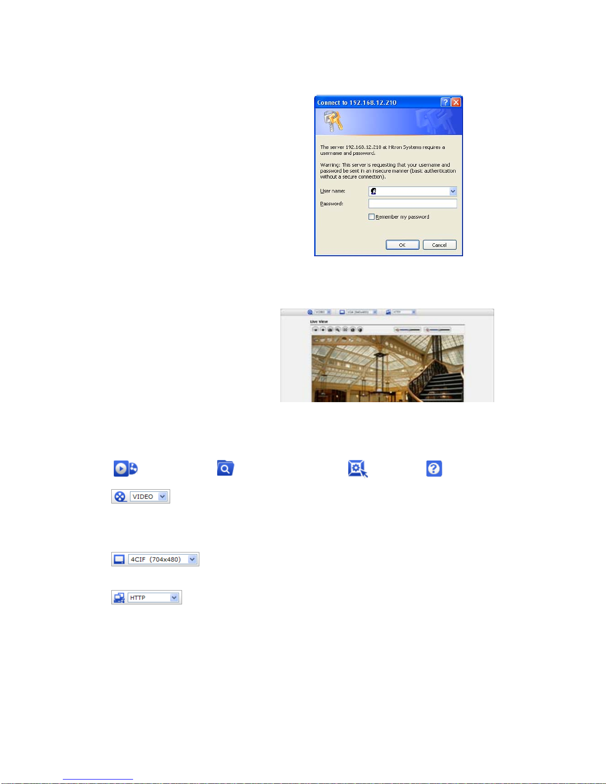
When accessing the Network Camera for the first time, the
“Admin Password” dialog appears. Enter your admin name
and password, set by the administrator.
Note: If the password is lost, the Network Camera must
be reset to the factory default settings.
See “3.6 Resetting to the Factory Default Settings”.
3.6 Resetting to the factory default settings
To reset the Network Camera to the original factory settings, go to the Setup>System >Maintenance
web page (described in “3.5.6 System>Maintenance” of the User’s Manual) or use the control button
on the network camera, as described below:
Follow the instructions below to reset the Network Camera to the factory default settings using the
Reset Button.
1. Switch off the Network Camera by disconnecting the power adapter.
2. Press and hold the Control Button with a straightened paperclip while reconnecting the power.
3. Keep the Control button pressed until the Status and Power indicator blink.
4. Release the Control Button.
5. When the Power Indicator changes to Green (may take up to 1 minute), the process is complete
and the network video transmitter has been reset.
6. The transmitter resets to factory defaults and restarts after completing the factory reset.
CAUTION: When performing a Factory Reset, you will lose any settings you have saved.
3.7 More Information
For more information, please see the Network Camera User’s Manual, which is available on the CD
included in this package.
10

REHXT0550-1, Quick Installation Guide
11

REHXT0550-1, Quick Installation Guide
HD NETWORK BOX CAMERA
Printed in Korea
This manual suits for next models
1
Table of contents
Other Revo Security Camera manuals

Revo
Revo RELPTZ22-3 Owner's manual

Revo
Revo REXT700-2 User manual

Revo
Revo RCHD24-1 User manual

Revo
Revo RESPTZ37-SERIES User manual

Revo
Revo Elite RESPTZ37-1 User manual

Revo
Revo REHB0309-1 User manual

Revo
Revo REHVDPTZ22-1 User manual

Revo
Revo REVDM600-1 User manual

Revo
Revo RCPTS700-1 User manual

Revo
Revo ELITE RETRT2812-1 User manual

Revo
Revo RECBP600-1 User manual

Revo
Revo NTSC User manual

Revo
Revo RCHB24-1 User manual

Revo
Revo REHCUW-1 User manual

Revo
Revo RECBH36-1 User manual

Revo
Revo REVDPTZ22-2 User manual

Revo
Revo RCBS20-1 User manual

Revo
Revo RETRT700-1 User manual

Revo
Revo REHXN0412-1 User manual

Revo
Revo REHVD0309-1 User manual