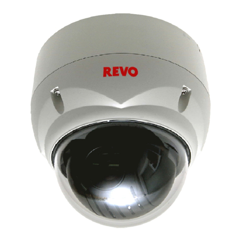
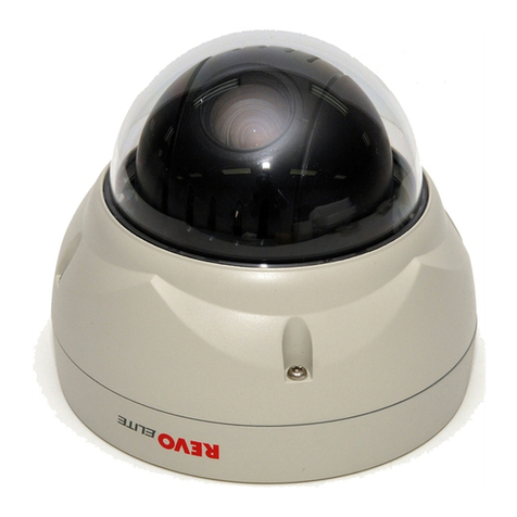
Revo RCPTS700-1 User manual

1
Model No.: RCPTS700-1
PAN/TILT DOME CAMERA
INSTRUCTION MANUAL
V0.1

2
Thank you for purchasing this product. Before installing the
camera, please read this instruction manual carefully to ensure
proper usage.
1. Safety Precautions
Take care when installing the camera. Do not connect
power unless the camera’s gimbal is free to turn normally.
After initial configuration, do not apply power to the
camera until the installation is complete.
Wiring: Use appropriate cables and wires for video,
power, and RS-485 connections.
Electrical Safety: The camera’s installation must be in
accordance with all applicable electrical codes and
ordinances.
Cleaning: Use only water and a soft, clean cloth to clean
the camera’s transparent dome, taking care not to scratch
it. Use only a soft cloth, water, and a mild detergent to
clean the camera’s painted metal enclosure and mounting
bracket.
Ensure that the camera’s transparent dome is tightened
securely before use. Do not allow any liquid or foreign material
into the body of the camera, as doing so may cause irreparable
damage.
Do not operate the camera beyond the specified temperature

3
range of -13°F (-25° C) to +122°F (+50°C). Only operate the
camera in environments with non-condensing humidity levels
less than 90%.
Do not install the camera near the air outlet of an air conditioner
or heater, or in any environment with rapid temperature
fluctuations.
Do not install the camera in any environment where the
humidity might change rapidly, or in an environment with
excessive smoke or dust.
Avoid pointing the camera’s lens directly at any intense source
of light, such as the sun, as sensor damage may result.
2. Description
The indoor pan/tilt camera uses a highly sensitive 1/3” CCD color
image sensor that provides long life and high reliability and is not
subject to distortion from magnetic fields.
This camera is easy to install and is an excellent choice for your CCTV
system.
3. Features
1/3” CCD color image sensor.
Auto White Balance.
Day Mode / Night Mode operation (Color image when adequate
light is present, Black and White image in low light conditions)
Precise stepper motor controlled pan/tilt mechanism allows remote
operation, using an RS-485 signal, from a DVR or a joystick
keyboard controller.
Continuous horizontal 360° panning rotation (left/right) and 90° tilt
angle (up/down) motion.
Settable RS-485 address (ID) allows additional cameras to use the
same RS-485 wiring.

4
Automatic protocol detection: Pelco-D and Pelco-P.
Settable baud rate.
Adjustable motor speed.
212 presets (saved horizontal and tilt angle views) can be saved
and retrieved.
Auto Tour - The camera can automatically tour through any of 8
different ordered lists, each containing as many as16 presets.
Auto Scan –The camera will pan continuously or back-and-forth
between set limits.
Sensitive to infrared light for use with external infrared light
sources in dark environments.
4. Contents
1.
Item
Name
Quantity
1
2.
Camera
1
2
3.
Instruction Manual
1
3
4.
Bag
1
3A
5.
Fixed Retaining Screws for Mounting
4
3B
6.
Plastic Anchors
4
5
7.
100ft. Cable (Video, Power, RS-485)
1
6
8.
Wall Adapter 120VAC to 12VDC@1A
1
9.
10.
11.

5
12.
5. RS-485 Address, Protocol, and Baud Rate Setting.
Address (ID) setting:
Set DIP switches 1 (least significant bit) through 8 (most significant
bit) to set the RS-485 address of the camera. The address can be
set from 0 through 255, and must be matched to the RS-485
address (often called the “ID”) in use by the controlling DVR or
joystick keyboard. Once set, the camera’s address does not need
to be changed. If more than one RS-485 device is connected using
the same RS-485 wiring, make sure that each device has a different
address.
A switch in the “up” (or “ON”) position is set to 1.
A switch in the “down” (or “OFF”) position is set to 0.
Note that some DVRs or joystick keyboards may not support an
address of 0 (00000000 on DIP switches).
The address is interpreted by the camera as reversed binary, such
that address 1 would be set as 10000000, and address 128 would
be set as 00000001. The first several RS-485 addresses are as
follows:
DIP Switch
Address
DIP Switch
Address
DIP Switch
Address
DIP Switch
Address
00000000
0
11110000
15
01111000
30
10110100
45
10000000
1
00001000
16
11111000
31
01110100
46
01000000
2
10001000
17
00000100
32
11110100
47
11000000
3
01001000
18
10000100
33
00001100
48
00100000
4
11001000
19
01000100
34
10001100
49
10100000
5
00101000
20
11000100
35
01001100
50
01100000
6
10101000
21
00100100
36
11001100
51
11100000
7
01101000
22
10100100
37
00101100
52
00010000
8
11101000
23
01100100
38
10101100
53
10010000
9
00011000
24
11100100
39
01101100
54
01010000
10
10011000
25
00010100
40
11101100
55
11010000
11
01011000
26
10010100
41
00011100
56
00110000
12
11011000
27
01010100
42
10011100
57
10110000
13
00111000
28
11010100
43
01011100
58
01110000
14
10111000
29
00110100
44
11011100
59

6
Baud rate setting:
Set DIP switches 9 and 10 to set the RS-485 baud rate of the
camera. The baud rate can be set to 2400, 4800, 9600, or 19200
bps. Make sure that the baud rate of the camera matches the
baud rate of the controlling DVR or joystick keyboard.
A switch in the “up” position (“ON”) is set to 1.
A switch in the “down” position (“OFF”) is set to 0.
Baud rate DIP switch table:
DIP
Switch
2400 bps
4800 bps
9600 bps
19200 bps
9
0 (Down or OFF)
1 (Up or ON)
0 (Down or OFF)
1 (Up or ON)
10
0 (Down or OFF)
0 (Down or OFF)
1 (Up or ON)
1 (Up or ON)
NOTE: The camera must be powered down and then
powered up to enable any changes made to the DIP
switch settings.
Protocol setting:
No camera settings are needed, as the camera will automatically
detect Pelco-D or Pelco-P protocols. Make sure that the controlling
DVR or joystick keyboard has been set to use only Pelco-D or
Pelco-P as the RS-485 protocol.
If your DVR or joystick keyboard has additional RS-485 settings,
make them match the following:
Data Bit: 8 Stop Bit: 1 Parity: NONE

7
6. Function Numbers
Function Set/Call (Store/Retrieve):
A preset point (“Preset”) is a memorized pan/tilt camera position.
Many presets can be set (created) and then called (retrieved) easily
to avoid having to use a mouse or joystick to move the camera
precisely to a desired view.
The camera supports a maximum of 212 presets.
The method to set and call presets will depend on the method of
camera control (for example, REVO Remote Pro on a PC, REVO
Mobile on a mobile device, direct DVR control or control via a
joystick keyboard.) Refer to the user’s documentation for the
controlling device. In general, the preset number (which is stored in
the camera) and the function (set or call) will be supplied to the
camera using the controlling device.
To set (create) a preset position, first move the camera’s pan axis
and tilt axis to the desired view, then use the controller’s preset “set”
command and the desired preset number. The view will be stored in
the camera.
To call (view) a preset position, use the controller’s preset “call”
command and the desired preset number to tell the camera to move
to the previously stored view.
For example, if the REVO Mini Keyboard is being used to control the
camera, “set” and “call” can be performed by doing the following:
A “set” command can be made by inputting the desired function
number on the keyboard, then pressing the “PRESET” button.
A “call” command can be made by inputting the desired function
number on the keyboard, then pressing and holding the “SHIFT”
button, then pressing the “PRESET” button, and then releasing
both buttons at the same time.
NOTE: Not all function numbers are used to store preset
(camera view) positions. Some function numbers are used for
special camera functions. Please refer to the following chart.
8
Function
Number
Function
Function Description
1 - 16
Presets
“Set” to save view, “Call” to move camera to view.
17 - 32
Presets
“Set” to save view, “Call” to move camera to view.
33
Preset
“Set” to save view, “Call” to move camera to view.
34
Reset
Camera’s
Origin
“Call” to reset the camera’s motors to their factory
origins. Do this if the presets fail to point properly.
35
Left Limit
Auto Scan
“Set” to define the camera’s left-most limit during
Auto Scan.
36
Right Limit
Auto Scan
“Set” to define the camera’s right-most limit during
Auto Scan.
37
Preset
“Set” to save view, “Call” to move camera to view.
38
Auto Scan
“Call” begins an Auto Scan between the left and right
limits set with functions 35 and 36.
“Set” clears the left-most (35) and right-most (36)
limits for Auto Scan.
39
Preset
“Set” to save view, “Call” to move camera to view.
40
Reset
Camera
“Set” resets the camera to factory defaults, and
erases all settings except right and left limits (35 and
36).
NOTE: THIS WILL DELETE ALL SAVED PRESETS!
41
Auto Tour 1
“Call” moves the camera automatically between
presets 1 through 16.
“Set” deletes all presets between 1 and 16.
42
Auto Tour 2
“Call” moves the camera automatically between
presets 17 through 32.
“Set” deletes all presets between 17 and 32.
43
Auto Tour 3
“Call” moves the camera automatically between
presets 65 through 80.
“Set” deletes all presets between 65 and 80.
44
Auto Tour 4
“Call” moves the camera automatically between
presets 113 through 128.
“Set” does not delete presets between 113 and 128.
45
Auto Tour 5
“Call” moves the camera automatically between
presets 129 through 144.
“Set” does not delete presets between 129 and 144.
46
Auto Tour 6
“Call” moves the camera automatically between
presets 145 through 160.
“Set” does not delete presets between 145 and 160.
47
Auto Tour 7
“Call” moves the camera automatically between
presets 161 through 176.
“Set” does not delete presets between 161 and 176.
48
Auto Tour 8
“Call” moves the camera automatically between
presets 177 through192.
“Set” does not delete presets between 177 and 192.
49
Not Used
Not Used
50
Preset
“Set” to save view, “Call” to move camera to view.

9
Function
Number
Function
Function Description
51
Pause Time
Auto Tour
“Set” this function number to change the Auto Tour
pause time to 2 seconds.
52
Pause Time
Auto Tour
“Set” this function number to change the Auto Tour
pause time to 4 seconds.
53
Pause Time
Auto Tour
“Set” this function number to change the Auto Tour
pause time to 6 seconds.
54
Pause Time
Auto Tour
“Set” this function number to change the Auto Tour
pause time to 8 seconds.
55
Pause Time
Auto Tour
“Set” this function number to change the Auto Tour
pause time to 10 seconds.
56
Not Used
Not Used
57
Preset
“Set” to save view, “Call” to move camera to view.
58
Preset
“Set” to save view, “Call” to move camera to view.
59
Preset
“Set” to save view, “Call” to move camera to view.
60
Motor Speed
Pan/Tilt
“Set” this function for fast dome motor speed.
“Call” this function for very slow dome motor speed.
61
Speed
Auto Scan
“Set” this function to set the Auto Scan pan speed to
6
° per second.
62
Speed
Auto Scan
“Set” this function to set the Auto Scan pan speed to
9
° per second.
63
Speed
Auto Scan
“Set” this function to set the Auto Scan pan speed to
15
° per second.
64
Speed
Auto Scan
“Set” this function to set the Auto Scan pan speed to
40
° per second.
65 - 80
Presets
“Set” to save view, “Call” to move camera to view.
81 - 112
Presets
“Set” to save view, “Call” to move camera to view.
113 - 128
Presets
“Set” to save view, “Call” to move camera to view.
129 - 144
Presets
“Set” to save view, “Call” to move camera to view.
145 - 160
Presets
“Set” to save view, “Call” to move camera to view.
161 - 176
Presets
“Set” to save view, “Call” to move camera to view.
177 - 192
Presets
“Set” to save view, “Call” to move camera to view.
193 - 254
Presets
“Set” to save view, “Call” to move camera to view.

10
7.
Pan/Tilt Dome Camera Installation
Unscrew the dome camera’s transparent dome. Set the DIP
switches for the desired address (ID) and baud rate. Use an
RS-485 DVR or joystick keyboard to verify the camera’s
operation. When proper RS-485 operation has been verified,
reattach the dome, securing it tightly.
Determine the camera’s location, and mark the location of the
mounting screw holes.
Drill holes in the mounting surface, and affix the camera using the
supplied screws and plastic anchors. The BNC video cable can go
straight through an additional, larger hole drilled into the mounting
surface, or against the mounting surface using the slot at the bottom
of the camera’s base.

11
Connect the camera’s BNC video cable and RS-485 wiring to your DVR
and (optional) joystick keyboard.
Ensure that the camera’s RS-485 “+” wire is connected to the
controlling device’s “+” or “A” connection.
Also ensure that the RS-485 “-” wire is connected to the controlling
device’s “-” or “B” connection.
Supply 12VDC to the camera using the 2.1mm power connector.

12
8.
Specifications
Model No.: RCPTS700-1
Image Sensor
SONY EFFIO-E CCD
Image Sensor Size
1/3
”
Video Signal
NTSC
Resolution
700TV (Color)
Effective Pixels
976 horizontal, 494 vertical
Minimum Illumination
0.05LUX in Black-and-White “Night” mode
SNR
58dB
White Balance
Auto
Electronic Shutter
1/60 to 1/12000 sec.
Focal Length
6.0mm
Presets
212 individually settable preset points (camera views)
Auto Tour
8 groups, 16 presets per group. Settable pause time between preset points.
Auto Tour Pause
The dwell on each preset point in an Auto Tour list can be set to 2, 4, 6, 8 or 10 seconds.
Auto Scan
Panning can be continuous or back-and-forth between defined horizontal limits.
Rotation range
Horizontal 360° (unlimited rotation). Vertical 90°
Rotation speed
Horizontal & Vertical Min 0.01° to Max 300°/second.
Communication mode
RS-485. PELCO-D and PELCO-P protocols are automatically detected
Power supply
12VDC @ 1A (Max. current draw of camera is approx. 0.55mA @12VDC)
Material
Cast Aluminum
Dimension
Approx. 5” x 8” x 8”
Table of contents
Other Revo Security Camera manuals

Revo
Revo RECDH2812-3 User manual

Revo
Revo RETRT700-1 User manual

Revo
Revo REVDPTZ22-2 User manual

Revo
Revo REHVDPTZ12-1 User manual

Revo
Revo RCDY24-1 User manual

Revo
Revo RESPTZ37-SERIES User manual

Revo
Revo RCBS20-1 User manual

Revo
Revo REVDN700E-2 User manual

Revo
Revo REHXT0550-1 ELITE HD User manual

Revo
Revo RBULRJCAM User manual

Revo
Revo RBULRJCAM User manual

Revo
Revo REHCUW-1 User manual

Revo
Revo RCHB24-1 User manual

Revo
Revo RECBP600-1 User manual

Revo
Revo REHXN0412-1 User manual

Revo
Revo NTSC User manual

Revo
Revo REHB0309-1 User manual

Revo
Revo REHVDPTZ22-1 User manual

Revo
Revo Elite RESPTZ37-1 User manual

Revo
Revo RECBH36-1 User manual