Rexing M2 User manual

M2
Users Manual

2
Notice
1. The user menu is to be set up in non-video mode. If the device is in video
mode, please proceed only after stopping the video recording.
2. Memory Card: Using a new MicroSD card always requires formatting it to
your device. Regularly clear the memory card, as continuous video recording
for an extended period of time may produce some protected files that are not
subject to long-term protection (these files may not be overwritten during loop
recording) and some storage fragments, which must be cleared regularly in
order to save usable storage space.
3. Time-lapse photography should not be enabled while driving. This function
captures images more slowly than normal but plays in speed-up mode, which
may affect the integrity and continuity of your video.
4. On-board Charger: The standard input voltage is configured to 12V. If a
voltage greater than 12V, contact your dealer or our customer care via
5. The features described in this operation manual are available for all products
of the same type. The device you buy may be a model with optional or
additional functions. Menu operations may vary. Please refer to your actual
product.
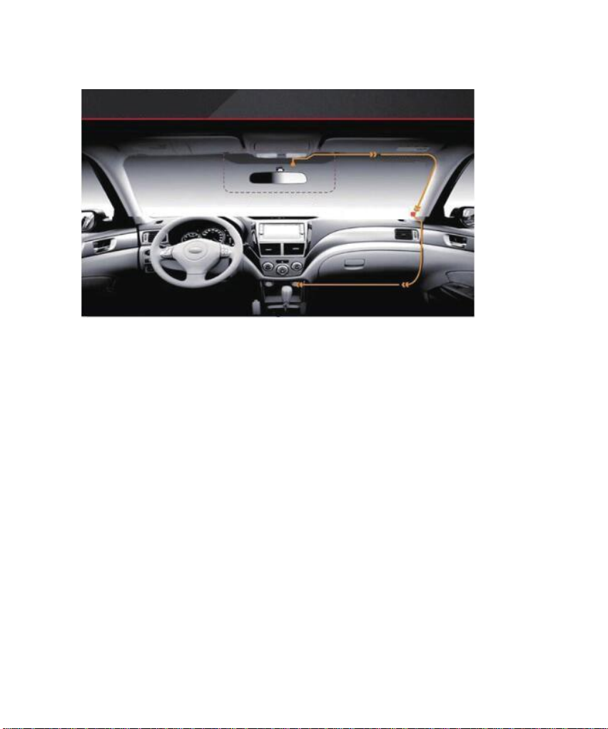
6. Pay attention to the mounting position, which must not interfere with driving
or lead to unsafe driving operation. Make sure it is safely secured.
7. A standard 6-meter cable is provided for the rearview camera. It is not
recommended to install this type of dash cam if your car is beyond the
connection cable range.

3
Warning
The battery (module or pack) must not be expose to an overheat environment
such as direct sunlight or flame.
Never remove, strike, or squeeze the battery or put it in fire. Stop using the
battery if it is ballooned, warped, leaking, or shows any other visible signs of
damage.

4
Overview
Thank you for choosing REXING! We hope you love your new products as
much as we do.
If you need assistance, or have any suggestions to improve it, please contact
Our support team will respond you as soon as possible.
Always a surprise in Rexing. Check us out here.
https://www.facebook.com/rexingusa/
https://www.instagram.com/rexingdashcam/
https://www.rexingusa.com/support/registration/

5
Table of Contents
Camera Overview............................................................5
Installation and Operation……………………..............8
Basic Operations………………………………………12
Product Specifications……………………………...…32
General Troubleshooting…………………………...…33

6
Camera Overview
GPS Port
USB Port
MicroSD Card
Slot
Rearview
Camera Port
Speaker
Display/Touch
Screen
Front Camera
Power Key
Reset Key
Pinhole
MIC Pinhole

7
Designation
Description of Functions
Power Button
In connection with an external power source, in the power-off
state, press or depress this button to start the device. In a
power-on state, depress this button to switch off the device.
In a power-on state, press this button quickly to turn the screen
backlight off. Press it again to turn on the backlight.
Display/Touch
Screen
Except for power-on/off operation, all the primary functions can
be accessed by clicking on the corresponding function button.
Some functions are accessed through a screen swiping operation.
Reset Key
If the device crashes, quickly press the reset key to resume
normal operation.
USB Port
Charging port
GPS Port
Optional. GPS logger sold separately.
TF Slot
A slot for inserting a MicroSD card
Front Camera
Front camera faces the same direction as the front of the vehicle
and captures videos/images in front of the car.
Rear Camera
Port
Rear camera plug-in port

8
Installation and Operation
Due to excessive mishandling, this device could be damaged during
transportation. To avoid high cost of troubleshooting and repairs due to
repeated mounting and removal, we recommend that you assemble all
components first after delivery and test the device with the on-board
charger power supply. Make sure that the device is visibly undamaged
prior to installation. Contact our service center in case of any questions.
I. Install the Device
1. Turn off the engine of the car.
2. Place the MicroSD card into the slot.
3. Secure the dashcam to the original rearview mirror of the car.
4. Plug the GPS module (sold separately) into the GPS port and secure the
module to a position close to A-pillar of the car. The antenna receiver side (the
side without 3M adhesive) faces the outside and the side with 3M adhesive
faces down. It should be properly secured.
5. Plug the charger into the car’s cigarette lighter and connect it to the dash
cam’s USB port with the included extended USB cable.
Note: The optional rearview camera is mounted on the rear of the car. Pay
attention to its orientation during installation. Plug the rearview camera
connector into the corresponding port of the dashcam once the installation is
completed. Adjust the position of the lens to ensure that it aligns horizontal with
the ground. Start the engine to check the video functionality of the device.

9
(Power Supply Wiring Instructions)
II. Install the Rearview Camera (optional)
1. Some rearview cameras are connected through removable coupling
connectors. If you receive a product with a separated plug and socketed
cable, then connect the plug-in components properly according to the
illustrations below. To avoid damage to the pins and connector holes,
never use extra force while making connections. The earphone connector
of rearview camera cable must be plugged into the corresponding port of
the device.
Installation Instructions
Optimum Installation
Location
Power Supply Wiring
Location
Location of GPS
Module

10
2. Rearview Camera Wiring Instruction (as shown below)
The rearview camera has two wire routing options as shown in the above
figure. The first part of both options is characterized with concealing the wire
routing against the edges of the door(s).
A: The rearview camera can be mounted at the top of the rear window inside
the car.
B: The rearview camera can be mounted right above the car’s license plate.
Align the male portion and the female portion of the
rearview camera cable between the arrows before
pressing the connectors together.
Connected to rearview
camera
Connected to reversing light

11
Note: The device is configured with a streaming media rearview camera that
provides clear traffic view behind the car. To obtain clearer and more intuitive
images, it is recommended to mount the camera above the license plate (as
shown by option B).
3. Instructions for Reverse Trigger Wiring
The red wire of the car’s reverse gear wiring is connected to the positive end of
one of the car’s reverse light. Make sure that the car charger is energized during
use.
III. Turn on the Dash Cam
Connect the dash cam to the car charger after installation. Starting the car
engine will start the device. The built-in battery will be charged at the same
time.
Note: Due to unstable voltages caused by starting the car engine, a voltage
fluctuation in some vehicles may be especially obvious. If a flashing screen or
some other unforeseeable operating problem occurs when you start the engine,
it is recommended to unplug the device from the charger before starting the
engine, and then reconnect it after the engine is running.
Red

12
Basic Operations
I. Video Mode
Key Functions:
1. Return to the main interface
2. Return to the previous operation menu
3. Start/stop video recording
4. Take a snapshot
5. Locking/unlocking (if locked) a file
6. Audio recording on/off
7. Front/rear view switching
8. Time, date, and weekday display
9. Status bar: An icon that is illuminated indicates a corresponding enabled
function; a function that is disabled is shown in gray.
10. Adjustment of screen brightness. Click to decrease brightness and
click to increase brightness.
Thursday

13
11. Video recording state and duration
Video Recording Operation:
With a MicroSD card inserted in the device, it will record automatically in
video mode after starting. A red indicator will flash in the upper left corner
of the screen during video recording. Press the icon to stop recording.
Press the icon to start recording when no recording is active.
Press the icon to take a snapshot. Press the unlocked icon during
recording will lock the current video file and the icon will change to the locked
icon at the same time. Press the icon again to unlock the current
video and the icon changes to the unlocked icon .
Press the icon to stop audio recording. Touch the icon again to start
audio recording. Swipe the screen up/down to change the view from the front to
the rear image.
II. Main Interface
The default interface is video recording screen after starting. Press the
icon to access the main interface, which is the entry that can be used
to access all functions and setup menus. The interface is shown below.

14
III. Smart Driving Mode
Note: The Advanced Driver Assistance Systems (ADAS) feature
depends on the traffic conditions and the driving state information
obtained from the front camera and the Blind Spot Detection (BSD)
depends on the traffic conditions of blind spots and the driving
information obtained from the rear camera. When the display
shows the front camera image,ADAS enables. When display shows
the rear camera image, BSD enables. They cannot be enabled
simultaneously.
Outline
ADAS refers to Advanced Driving Assistant System. This model mainly
includes FCWS (Forward Collision Warning System), LDWS (Lane Departure
Warning System) and a stop & go function. That is, an alert or warning is
Dash Cam
Smart
Driving
File
Management
Driving Setup
System Setup
Thursday
Advanced Driving Assistant System
Blind Spot Monitoring System
Calibration
Setup
Calibration
Setup
Enable/Disable
Button
Tuesday

15
generated when a potential collision hazard with the car ahead is detected
during driving or it is about to deviate from its lane.
BSD refers to Blind Spot Detection, which monitors in real time any vehicle in
the blind spots on both sides during driving. It gives an alert so as to reduce the
risk of traffic accidents that are likely to occur when you intend to shift to
another lane. It is also called LCA (Lane Change Assist).
ADAS and BSD systems may be interfered with by sunlight, inadequate lane
lines, rain, and fog, Certain impacts may be affected by these inaccuracies, and
some collisions may not be avoidable. Currently, the ADAS provides a rate of
accuracy between 80 to 90 percent during the daytime and 60 to 70 percent at
night. BSD provides a rate of accuracy around 90 percent during the daytime
and around 80 percent at night.
The following instructions are mainly used for the calibration of the smart
driving application of the dashcam. It mainly includes the calibration of
ADAS and the blind spot monitoring range.
Before using ADAS, it is necessary to calibrate it according to its mounting
position and view angle of the dashcam. Only in this way can it detect vehicles
and lanes accurately.
Disclaimer: The system is a safe driving assistant system and it cannot be used
as a proof for the liability of traffic accidents.

16
ADAS Calibration
(ADAS Calibration Flow)
Start
Enter smart driving interface
Turn on ADAS
Enter ADAS setup interface
Exit ADAS setup interface
Enter ADAS calibration interface
Adjust by moving the red, green, and yellow lines
Save results and exit
End

17
Setup Steps:
1. Open the smart driving application and turn on ADAS (advanced driving
assistant system). The button turns from gray to blue.
2. Click to access the ADAS setup page. Click the option Front Car
Warning Time and select the appropriate option (a default value may be used).
FCWT refers to the warning time for a potential collision with the car in front.
3. Click the option Lane Change Line-Crossing Warning and select the
appropriate option (a default value may be used). LCLCW refers to the
sensitivity of line-crossing warning during a lane change. High, moderate, and
low indicators correspond to lane change line-crossing time 2s/3s/4s,
respectively.
Front Car Warning Time
ADAS setup
Front Car
Warning
Time
Lane Change
Line-Crossing
Warning
Tuesday
Lane Change Line-Crossing
Warning
ADAS Setup
Front Car
Warning
Time
Lane Change
Line-Crossing
Warning
Tuesday
High
Moderate
Low

18
4.Click to access the ADAS calibration page. You will initially see the
concept and a brief introduction on the calibration page. Click Next to access
the real calibration interface, as shown below. Move the red line up or down
align with the horizon (the intersection line between the sky and ground). Move
the yellow line up or down to the interface between the engine hood and
ground. Move the green line left or right to the focal point where the far end of
the road intersects with the horizon.
Note: The range of calibration line adjustment is limited. If the extreme
adjustment has reached the its limits and the result is unsatisfactory, it may be
necessary to adjust the mounting position of the dashcam or perform fine
adjustments of the lens so as to align it properly within all angles.
5. When the adjustment is accurate as shown above, save and exit.
ADAS Calibration
Move the red line to the
intersection line between the
horizon and Earth. Move the
green line to the focal point
where the road intersects with
the horizon. Move the yellow
line to the interface between
the engine hood and ground.
Save
Tuesday

19
Calibration For Monitoring Blind Spots
(BSD Calibration Flow)
Start
Enter Smart Driving Interface
Turn on BSD
Enter BSD setup interface
Exit BSD setup interface
Enter BSD calibration interface
Move the box left or right to adjust blind spot
warning range
Save the result and exit
End

20
Setup Steps:
1. Open the smart driving application and turn on BSD (Blind Spot Detection).
The button turns from gray to blue.
2. Click to enter BSD setup interface. Click the option Warning Speed
and select the appropriate option (a default value can be used). The Warning
Speed means that when any vehicle is detected within the set warning range, an
alarm is activated if the driving speed of the car is greater than the set value.
3. Click the option Warning Sensitivity and select an appropriate option (a
default value can be used). Warning Sensitivity means that when any vehicle is
detected within the set warning range, an alarm is activated if the driving speed
of the following vehicle is greater than that of the car. High: An alarm is
activated regardless of car speed. Moderate: An alarm is activated if the
following vehicle has a speed 10km/h greater than the car. Low: An alarm is
activated if the following vehicle has a speed 20kg/h greater than the car.
Car Warning Speed
BSD Setup
Car Warning
Speed
Warning
Sensitivity
Tuesday
Other manuals for M2
1
Table of contents
Other Rexing Automobile Accessories manuals
Popular Automobile Accessories manuals by other brands

Menabo
Menabo SIRIO KIT+1 Fitting instructions

AMP Research
AMP Research PowerStep installation guide

Roadmaster
Roadmaster 88336 installation instructions

Front Runner
Front Runner LAMS004 manual

Safe Fleet
Safe Fleet PRIME DESIGN AR-2010 Assembly instructions

freightliner
freightliner Park Smart technical information