manuals.online logo
Brands
  1. Home
  2. •
  3. Brands
  4. •
  5. Rheem
  6. •
  7. Heater
  8. •
  9. Rheem RTG-74X User manual

Rheem RTG-74X User manual

Tankless Water Heater Recess Box
Installation Instructions
The purpose of this manual is to provide the installer with
the basic instructions necessary to properly install the recess
box. This manual assumes that the installer has basic car-
pentry skills and plumbing knowledge. Local codes may
apply to this installation, all local building, electrical, and
plumbing codes should be followed.
It is imperative that all persons who are expected to install,
operate or adjust this recess box and/or water heater, read
these instructions along with those instructions provided
with the tankless water heater.
Recognize this symbol as an indication of Important
Safety Information!
Refer to the Use and Care Manual provided with your
tankless water heater for the proper installation proce-
dures and conditions.
!
Only these models of Outdoor Tankless Water Heaters
will t or function in this recess box;
RTG-74X GT-199X
RUTG-74X RMTG-74X
PTG-74X PH-28ROF
PH-28COF
WARNING!
Gasoline, as well as other ammable materials and liquids (adhesives, solvents,
paint thinners etc.), and the vapors they produce are extremely dangerous. DO NOT handle, use or store
gasoline or other ammable or combustible materials anywhere near or in the vicinity of a water heater
or any other appliance. Be sure to read and follow the labels on the water heater, as well as the warning
printed in this manual. Failure to do so can result in property damage, bodily injury or death.
!
1
Location - This water heater recess box is for OUT-
DOOR installation ONLY, and is intended for use only with
the water heater models listed above. Do not attempt to in-
stall a water heater of another brand or model in this recess
box.
Do not attempt to modify this recess box. Doing so will
alter the intended design potentially causing an unsafe op-
erating condition.
Consult the Use and Care Manual provided with your tan-
kless water heater for installation instructions regarding
a suitable location for the water heater. All guidelines re-
garding clearances and distances from overhangs, windows
and doors, and air inlets into the home must be followed.
Recess Box Clearances - This recess box is designed
to be installed with a Zero (0) clearance to combustibles.
For service and proper operation, 24”(61 cm) of clearance
is required in front of the recess box.
Freeze Protection - To help prevent water lines from
freezingdonotlocatewaterheateronthesideofabuildingwith
prevailing winter winds. Refer to the Use and Care Manual
provided with your water heater for additional information.
AP14006-1 (12/06)
Water Heater Exhaust Terminal Location
The following information should be used for determining the proper
location of the vent terminal for outdoor tankless water heaters.
WARNING: Moisture in the flue gas will condense as it
leaves the vent terminal. In cold weather this condensate can
freeze on the exterior wall, under the eaves and on
surrounding objects. Some discoloration to the exterior of
the building is to be expected. However, improper location
or installation can result in severe damage to the structure
or exterior finish of the building
(1.8 m)
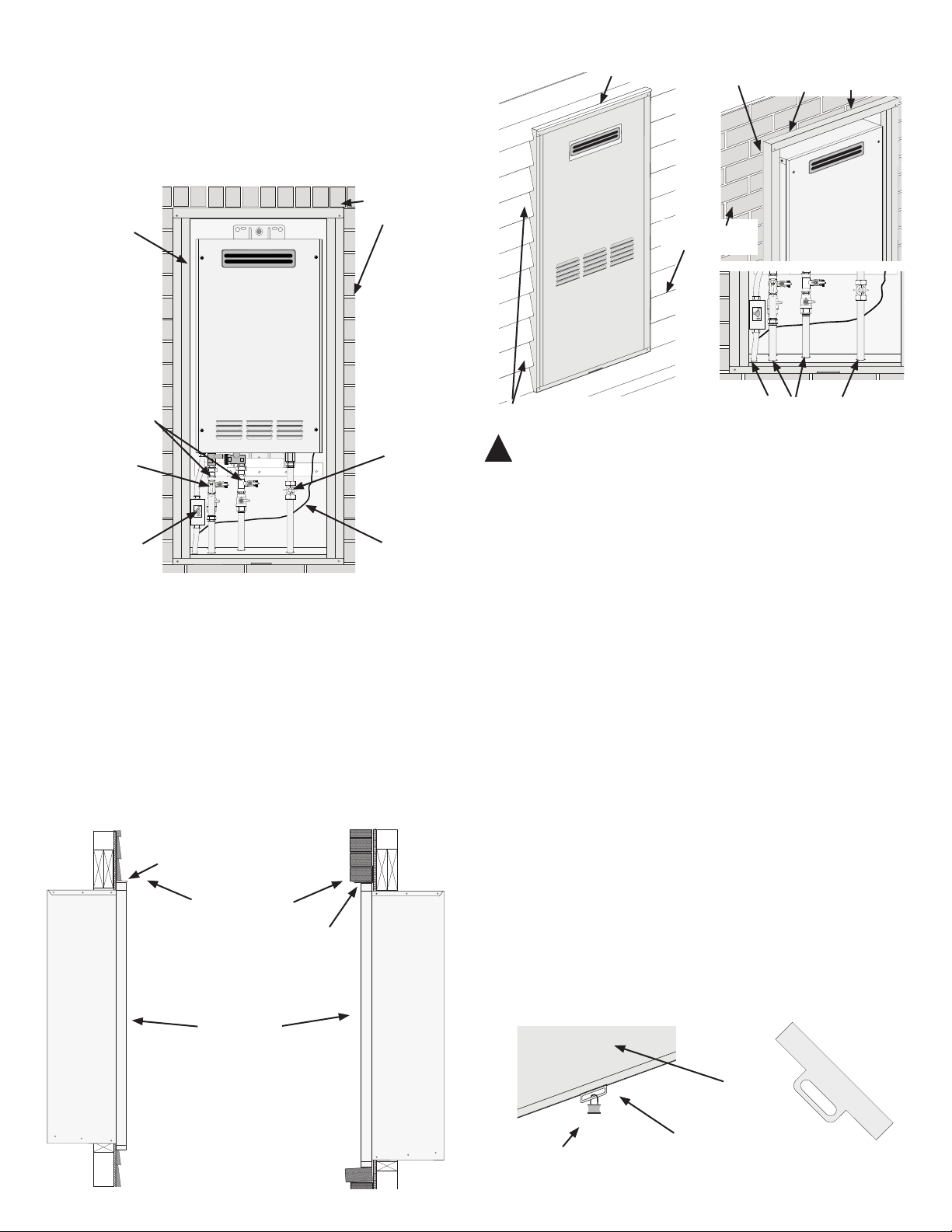
If soffit vent is too close,
block off and install new
vent at another location
Inside
corner
Caulk
Caulk
Caulk
6' (1.8 m)
caulk zone or to edge of
window etc., starting
within 6' (1.8 m)
Rising moisture will collect under eaves
4'
6' (1.8 m) caulk
zone
6'
(1.2 m)
Additional Considerations
Do not install water heater under
any patio or deck.
To help prevent moisture from
freezing on walls and under eaves,
do not locate the water heater on the
side of a building with prevailing
winter winds.
To help prevent water lines from
freezing do not locate water heater
on the side of a building with pre-
vailing winter winds.
Do not locate water heater too close
to shrubbery, as ue gasses may
damage them.
Caulk all cracks, seams and joints
within six (6) feet (1.8 m) of exhaust
vent.
Guard exhaust vent against acciden-
tal contact with people and pets.
Install the water heater such that the
air inlet and exhaust vent are above
anticipated snow levels
1.
2.
3.
4.
5.
6.
7.
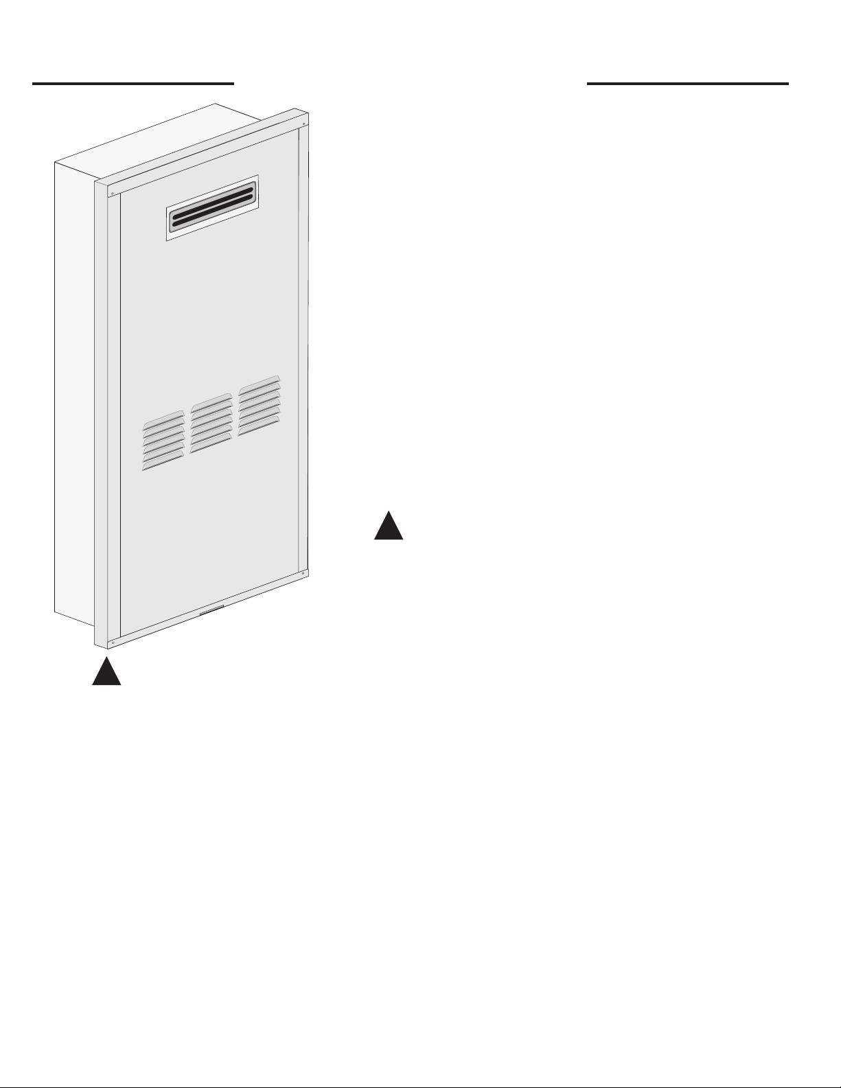
Recess Box Location - This water heater recess box is intended for an outdoor location only. Follow the
guidelines below or in the Use and Care Manual provided with the water heater for choosing a suitable location.
Figure 1 Figure 2
D
V
V
E
FIXED
CLOSED
OPERABLE
O
PERABLE
FIXED
CLOSED
v
v
B
L
F
C
B
v
vv
X
B
B
B
A
J
C
I
H
X
v
M
K
v
G
A
V
VENT TERMINAL XAIR SUPPLY INLET AREA WHERE TERMINAL IS NOT PERMITTED
Canadian Installations
1
US Installations
2
1 In accordance with current CAN/CGA-B149 Installation Codes.
2 In accordance with current ANSI Z223.1/ NFPA 54 National Fuel Gas Code.
+ A vent shall not terminate directly above a sidewalk or paved driveway that is located between two single family dwellings and
serves both dwellings.
* If clearances are not specified then follow local installation codes and the requirement of the gas supplier.
** For condensing appliances: The vent for this appliance shall not terminate over public walkways, near soffit vents, crawl space
vents, of other areas where condensate or vapor could create a nuisance, hazard, or cause property damage. Where
condensate or vapor could cause damage or could be detrimental to the operation of regulators, relief valves, or other
equipment.
H = Clearance to each side of center line
extended meter/regulator assembly.
above
3 feet (91 cm) within a height 15 feet
(4.57 m) above the meter/regulator
assembly.
*
I = Clearance to service regulator vent
outlet.
3 feet (91 cm) *
J = Clearance to nonmechanical air
supply inlet to the combustion air
inlet to any building or other
appliance.
6 inches (15 cm) for appliances < 10,000
Btuh (3 kW), 12 inches (30 cm) for
appliances > 10,000 Btuh (3kW) and
<100,000 Btuh (30kW), 36 inches (91
cm) for appliances > 100,000 Btuh
(30kW).
6 inches (15 cm) for appliances < 10,000
Btuh (3 kW), 9 inches (23 cm) for
appliances > 10,000 Btuh (3 kW) and
< 50,000 Btuh (15 kW), 12 inches
(30 cm) for appliances > 50,000 Btuh
(15 kW).
K = Clearance to mechanical air supply
inlet.
6 feet (1.83 m) 3 feet (91 cm) above if within 10 feet
(3 m) horizontally.
L = Clearance above paved side walk or
paved driveway located on public
property.
Not allowed Not allowed
M = Clearance under veranda, porch,
deck or balcony.
Not allowed Not allowed
A= Clearance above grade, veranda,
porch, deck or balcony.
12 inches (30 cm) above anticipated
snow level.
12 inches (30 cm) above anticipated
snow level.
B= Clearance to window or door that
may be opened.
6 inches (15 cm) for appliances < 10,000
Btuh (3 kW), 12 inches (30 cm) for
appliances > 10,000 Btuh (3kW) and <
100,000 Btuh (30kW), 36 inches (91 cm)
for appliances > 100,000 Btuh (30kW).
6 inches (15 cm) for appliances < 10,000
Btuh (3 kW), 9 inches (23 cm) for
appliances > 10,000 Btuh (3 kW) and
< 50,000 Btuh (15 kW), 12 inches
(30 cm) for appliances > 50,000 Btuh
(15 kW).
C= Clearance to permanently closed
window. * *
D= Vertical Clearance to ventilated soffit
located above the terminal within a
horizontal distance of 2 feet (61 cm)
from the center line of the terminal.
* *
E= Clearance to unventilated soffit. * *
F= Clearance to outside corner. * *
G= Clearance to inside corner. * *
2
Install the recess box into the opening, level and
square the box. Test fit the outer door to make
sure it does not bind during installation. Secure
the recess box to the framing on each side using
four or more self tapping screws (not provided).
Mount the water heater into the recess box. In the back
of the recess box is a channel to support the bottom
mounting bracket of the water heater. At the top is a
retaining stud for securing the top mounting bracket.
Lift the water heater up and slide the bottom mounting
bracket down into the channel. While holding the water
heater in place, secure the top of the unit to the retain-
ing stud with the washer and nut provided.
Plumbing and Piping -
See Figure 5 for Pipe Locations.
Follow all instructions in the Use and Care Manual for instal-
lation of gas and water lines. Holes are provided in the bot-
tom of the recess box for all piping and wiring. These holes
line up with the ttings on the bottom of the water heater.
Stub the water lines and gas pipe up through the bottom
of the box (See Figure 5). It is recommended that shut
off valves and unions be installed in the piping for
future service requirements.
Connect the water lines and gas piping to the water
heater in accordance with the instructions in the Use
and Care Manual provided with the water heater.
Seal the holes around the piping with a silicone based
sealant to prevent any water from leaking into the
wall behind the recess box. Insulate pipes with foam
insulation.
Power Disconnect - Install a suitable means to discon-
nect power from the unit for service. This disconnect should
be weather resistant and meet any and all local codes. In the
absence of local codes, the National Electrical Code should
be followed. Refer to the Use and Care Manual for instruc-
tions in connecting the power to the water heater.
2.
3.
1.
2.
3.
Rough In Dimensions
Height 41”(104 cm); Width 17”(43 cm);
Depth depends upon siding
Installation
The recess box is designed to be installed with a variety of
home exterior products for new or existing construction.
Choose a suitable location for the water heater and
recess box. Follow the guidelines listed on page 2 of
this manual, or the Use and Care Manual for the water
heater, regarding location and clearances. Frame an
opening in the exterior wall of the home for the rough
in dimensions in Figure 3. Local building codes and
standard building practices should be followed.
1.
Dimensions - Figure 3
Dim.* Inches /
cm
A 40 1/2
(103 cm)
B 16 3/4
(42.5 cm)
C 10
(25 cm)
D 1 3/8
(3.5 cm)
E 42 7/8
(109 cm)
F 21 1/4
(54 cm)
A
B
C
D
E
F
* Approximate
Cripple Stud
King Stud Trimmer Stud
Blocking
Header
Wall Stud
Sill
Typical Framing - Figure 4
Hot Water
Line
Thermostat
Wiring
Opening
Electrical
Opening
Relief Valve Drain
Gas Line
Cold Water
Line
3
Plumbing and Piping Openings - Figure 5
and the siding or brick of the house with a silicone based
sealant to prevent water from getting behind the box into
the wall.
Installing the Door - Lift the door up from the bottom
at a slight angle. Slip the door into the channel at the top of
the recess box. Next push the bottom of the door ush with
the recess box and slid down into the channel at the bottom
of the enclosure. Do not block any air openings of the door
Security Clip - Before installing the door, slide the clip
into the slot at the bottom of the door from the backside so
it points straight down through the bottom of the door. Lift
the door into place per the instruction above. As the door is
being slid down into place, guide the security clip into the
slot in the bottom channel of the recess box.
Once the clip is in place, secure with a suitable means (small
padlock, security tag, etc.).
Thermostat Wiring - A hole is provided for
the Thermostat wire(s). Route the wire through the
hole and connect the wire to the water heater accord-
ing to the instructions in the Use and Care Manual.
Final Assembly and Inspection - Follow the Use
and Care Manual for complete details about the water heat-
er. Check all water and gas connections for leaks.
Seal all openings around pipes and wires with an outdoor
grade silicone sealant. Seal the joint between the recess box
Caulk Joint Between Siding
and Recess Box
Seal all openings around pipes
and wires with a silicone sealant
Sealing and Finish - Figure 8
Drip Ledge
Outer Door
Caulk Joint Between Siding
and Recess Box
Siding or Brick
Security Clip - Figure 9
Padlock
Outer Door
Security Clip
Warning - All openings in the bottom of the recess box
must be sealed to prevent water inltration in to the wall. Fail-
ure to do so could result in damage to the wall.
!
Typical Installation - Figure 6
Recess Box
Wall Sheathing
(Brick, Vinyl, etc)
Outdoor
Tankless Water
Heater
Isolation Valves
Power Disconnect
Pressure
Relief Valve
Gas Service
Valve
Thermostat
Wire
Typical Installation and Finish - Figure 7
Drip Ledge
Siding or Brick
Recess Box
Brick Lintel
Lap Siding Brick Siding
4

This manual suits for next models

6

Other Rheem Heater manuals

Rheem 874826NF User manual

Rheem

Rheem 874826NF User manual

Rheem RXHK-D01 User manual

Rheem

Rheem RXHK-D01 User manual

Rheem Raypak MVB 503 Manual

Rheem

Rheem Raypak MVB 503 Manual

Rheem Raypak Raytherm P-926 Manual

Rheem

Rheem Raypak Raytherm P-926 Manual

Rheem Raypak D-2 Power Vent User manual

Rheem

Rheem Raypak D-2 Power Vent User manual

Rheem Raypak Hi Delta 302C User manual

Rheem

Rheem Raypak Hi Delta 302C User manual

Rheem Raypak AVIA 264 User manual

Rheem

Rheem Raypak AVIA 264 User manual

Popular Heater manuals by other brands

Unold 86706 Instructions for use

Unold

Unold 86706 Instructions for use

Brant Radiant Heaters LD Series Operation, installation, maintenance and parts manual

Brant Radiant Heaters

Brant Radiant Heaters LD Series Operation, installation, maintenance and parts manual

Thermocore F20 user manual

Thermocore

Thermocore F20 user manual

Kettler KALOS Ibiza Assembly instructions

Kettler

Kettler KALOS Ibiza Assembly instructions

Zeus DR57 installation manual

Zeus

Zeus DR57 installation manual

Sunjoy SR-4DSN user manual

Sunjoy

Sunjoy SR-4DSN user manual

Aerotherm ALIEN TURBO owner's manual

Aerotherm

Aerotherm ALIEN TURBO owner's manual

ReddyHeater RH80T manual

ReddyHeater

ReddyHeater RH80T manual

Dimplex DX 521 Installation and operating instructions

Dimplex

Dimplex DX 521 Installation and operating instructions

ARDES AR4B01B Instructions for use

ARDES

ARDES AR4B01B Instructions for use

Sundirect BC004 installation manual

Sundirect

Sundirect BC004 installation manual

OYPLA DIY 4714 user manual

OYPLA DIY

OYPLA DIY 4714 user manual

Limora 501350 Instructions for use

Limora

Limora 501350 Instructions for use

Comet ORC9F2000 owner's manual

Comet

Comet ORC9F2000 owner's manual

Sonnenkonig VENTUS DIESEL 20 manual

Sonnenkonig

Sonnenkonig VENTUS DIESEL 20 manual

Lindab IMP Klima instructions

Lindab

Lindab IMP Klima instructions

GiveBest HPQ15C-EA user manual

GiveBest

GiveBest HPQ15C-EA user manual

Oceanic OCEAISHFT1000W user manual

Oceanic

Oceanic OCEAISHFT1000W user manual

manuals.online logo
manuals.online logoBrands
  • About & Mission
  • Contact us
  • Privacy Policy
  • Terms and Conditions

Copyright 2025 Manuals.Online. All Rights Reserved.