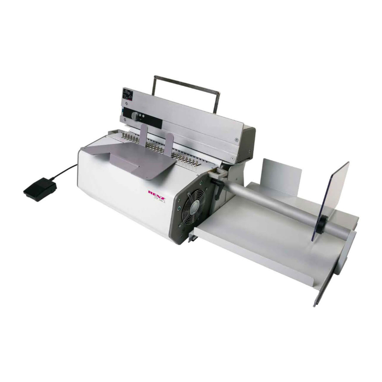
Rhin-O-Tuff OD4012 User manual

Instruction Book
for the OD4012

OD4012
Setup & Operator Manual
Issue 4 April 2014
Performance Design LLC.
This punch has been designed to punch most any job that may pass
through your office. No matter what type of binding you need to carry out,
this punch can handle the job. The maximum single punching length for
the OD4012 is a 11” (297mm) format. The OD4012 is an electrically
operated punch and utilizes a simple two knob die lock system to retain
the die punch assemblies.
2
OD4012

OD4012 Contents S/N:____________
___Punch (1) ___Instruction Book (1)
___Oil (1) ___Brush (1)
___Foot Pedal (1) ___Power Cord (1)
___Reversing Tool (1)
Inspected by: __________________


Table of Contents
Topic: Page Number:
3
Safety Alert Symbols
Safe operating guidelines
Proper machine placement
Providing electric power
Die installation / Maintenance
Setting the paper stop/guide
Punching paper
Removing paper waste
Paper jam
Troubleshooting
4
4
5
6
6-8
9
9
9
10
11

Safety Alert Symbols
uThe OD4012 needs to be plugged into a wall outlet that provides a 15-
amp, 120 volt service (16-amp, 220 volt for European installations)
and is protected by a fuse or circuit breaker at the main electrical
panel.
uIf machine cycles on its own, turn off power switch, unplug machine
from the wall outlet and call your dealer immediately for service.
uMake sure you read this section very carefully! Learn to recognize
these The OD4012 has been designed to
provide a high level of protection to an operator. Follow the guidelines
below while installing, operating and maintaining your machine.
Safety Alert Symbols.
4
!DANGER
!WARNING
Safe Operating Guidelines
!CAUTION CAUTION: Indicates a hazardous situation which, if not avoided, could result in
minor or moderate injury. It may also be used without the safety alert symbol as
an alternative to "Notice".
WARNING: Indicates a hazardous situation which, if not avoided, could result in
death or serious injury.
DANGER: Indicates a hazardous situation which, if not avoided, will result in
death or serious injury. This signal word is to be limited to the most extreme
situations.
Trip Hazard
Two Person LIft
Electric Shock
Crushing Hazard
uAlways replace any fuse with the same type and
amperage fuse as indicated on the machine.
Hazardous voltage
inside.
Disconnect power
before servicing.
!WARNING
Cutting Hazard
Hint or Suggestion
uAlways keep this instruction manual with the machine for reference to
safe operating guidelines and correct operation of the machine.


5
Placing your machine in the proper location:
uBefore lifting machine, turn power off and
remove the power cord from the wall outlet.
The machine is very heavy! Never attempt to lift
the machine by yourself. Two people will be
needed to lift the machine.
uPlace the machine on a hard level surface, place the foot pedal on the
floor in front of the machine. Ensure the placement of machine allows
for ergonomic work flow (separate locations for un-punched books and
punched books).
u
u
Connect the foot-pedal into the foot-pedal
receptacle on the back of the machine, do not
attempt to connect foot-pedal into anything other
than the foot-pedal receptacle.
paper activated switches are available
for these punches. These switches replace the foot-
pedal and plug into the foot-pedal receptacle on the
back of the machine.
Optional
Lifting Hazard
Single person
lift could result
in injury.
Two person lift required.
!CAUTION
uTurn power switch off before maintaining or
changing die assembly.
!WARNING
Crush hazard.
Keep hands away
from moving parts.
Lockout and disconnect
power before servicing.
!CAUTION
Cutting Hazard
Injury to fingers
and hands.
Use hand protection
uUse of appropriate hand protection should be
utilized to avoid injury from handling of materials.
uFollow all recommended workplace procedures for repetitive activities.
!CAUTION
Tripping Hazard
Bodily injury could
occur from fall.
Route cables away
from walkways

6
Providing power to the machine:
uPower cord shall be certified for the country
where the machine will be installed. Plug one
end of the power cord into the power cord
receptacle on the back of the machine. The
other end goes into the wall outlet.
Die Installation:
u
u
u
u
u
Diagram 2.
.
Make sure there is no paper dust or paper chips
in the machine die slot before installing the die.
Install the die by sliding it into the opening
located on the left hand side of the machine. Make sure the punch pin
retainer slides into the slot on the backside of the opening.
Install die until right side of die is flush to exterior of right side of
machine.
Thread both retained die lock knobs into the die and tighten evenly
until the die can not move.
Make sure the machine is turned
off before installing the die
Diagram 2. (Image of OD4012)
!DANGER
Hazardous voltage.
Use only approved
power cord
assemblies.
!WARNING
Crush hazard.
Keep hands away
from moving parts.
Lockout and disconnect
power before servicing.
Die Lock Knob
Punch Pin
Retainer

7
Comb Die Backspace (Margin) Adjustment
uThe comb die assemblies for the OD4012 have a four position
adjustable backspace. The positions are changed by pulling the
adjustor bar to the left for deeper settings (commonly used for average
to thicker sized books) and pushing the adjustor bar to the right for
shallower settings (commonly used for thinner sized books).

8
Removing Punch Pins
?Turn machine power off and remove die
assembly from the machine.
On the opposite side of the die assembly from
the die handle, .push down on the pin retainer
Remove the desired punch
pin or pins.
Replace the pin capture by pressing down on the pin retainer and
placing the pin capture back into place.
?Install die assembly into machine as described earlier and turn
machine power back on.
uDie maintenance should be performed with the die removed from the
machine. To perform the die maintenance, remove the die assembly
from the machine (see die installation section). Apply enough oil to
lightly coat each pin.
Remove any excess oil with a disposable cloth. After oiling, always
punch some scrap paper to remove excess oil.
u
Saturate a small section of a
cloth with oil and using that
portion of the cloth, wipe the
punch pins to apply a light
coating of oil.
Die Maintenance
?Pull the pin capture away from the pin retainer
to expose the punch pins.

9
Setting the paper stop/guide:
u
u
OD4012-
Locate the paper stop on the front cover of
the machine. Loosen the knob
counterclockwise, so that the guide can be
adjusted to the left or the right.
until the punch
pattern is centered on the paper.
The OD4012 punch machine allows for viewing of the common
size paper position markings on the die assemblies. Aligning
the paper stop with these marks will result in the punch pattern
being centered on the paper and need only small adjustments if
at all.
Move the
paper stop until the desired position is
reached and tighten the knob clockwise
until tight to lock the paper stop in place.
Repeat this procedure
Punching Paper:
uSelect an appropriate number of sheets to be punched and slide the
sheets down vertically into the opening of the die assembly. When the
paper is fully inserted, slide it to the left so it comes in contact with the
paper stop. Make sure all the edges of the sheets are flush by tapping
the top and the right hand sides of the sheets then activate the punch
by depressing the foot-pedal.
If a paper activated switch is being used, tap the sheets flush
before sliding the paper to the paper stop.
Removing Paper Waste:
uThe paper waste drawer is located conveniently on the front of the
punch. The paper waste drawer is removed by lifting up on the front
and pulling out away from the machine. This drawer should be
checked frequently while punching and emptied as necessary.
Paper Stop

10
Paper Jam:
uThe OD4012 punch uses a circuit board for controlling the punch
cycle, this circuit board also has the ability to automatically reverse the
pusher bar and punch pins to their starting position if the machine
takes too much time to complete a punch cycle. This condition could
happen if too much material has been attempted to be punched at one
time. If this condition occurs, allow the machine to attempt to reset
itself back to its home position.
uIf the punch does not reset itself back to its home position, the punch
will need to be reversed manually.
!WARNING
Crush hazard.
Keep hands away
from moving parts.
Lockout and disconnect
power before servicing.
uTurn the machine power switch off and
remove some or all of the material in the
punch.
It is easier to remove one or two sheets at a time from the
backside of the material in the punch.
uOD4012 Manual Reverse utilizes a reversing
tool supplied with the punch.
Locate the
silver plug on the rear of the left side panel of
the machine. Remove the silver plug by prying it out gently with a
small flat tool. Insert the end of the reversing tool into the open hole
and engage the tool with the end of the motor shaft. Rotate the tool
counterclockwise 5-10 revolutions, until the punch pins have been
retracted back to the starting position. Remove most or all of the
material from the punch. Remove the reversing tool from the punch
and replace the small silver plug. Plug the power
cord back into the wall outlet and turn the power
switch on. Test cycle the machine by punching
with no material in the punch, the machine will
reset itself back to its home position. Reduce the
amount of material being punched and continue
working.
Turn the
machine power switch off and unplug
the power cord from the wall.
!WARNING
Crush hazard.
Keep hands away
from moving parts.
Lockout and disconnect
power before servicing.

11
Machine does not cycle
Symptom Possible Cause Action
Troubleshooting
Die does not go into machine
1) Machine is off
2) Machine is not plugged in
3) Foot-pedal is not plugged into
machine
4) Die lock handle is not locked
5) Reversing tool is in machine
1) Pin retainer interference
2) Punch is stopped in mid cycle
3) Die lock handle is in lock position
1) Check power switch
2) Check both ends of power cord
3) Make sure foot-pedal cable is
attached to machine.
4) Lock the die lock handle
5) Remove reversing tool and
store properly
1) Make sure pin retainer enters slot
in pusher-bar.
2) Restart machine by turning power
off and back on
3) Move handle to unlock position
Only qualified personnel should attempt to
work on this equipment. There are no user
serviceable parts inside of the machine.
Your machine has been designed for years of trouble free operation. The
following is a troubleshooting guide to help you through some of the
problems that may be encountered.
The OD4012 has earned the UL Listing Mark. E179574.
The OD4012 has been tested with a duty cycle of
25 cycles per minute with a 1 minute rest period
after 2 minutes of run time. Operating outside of these limits could result
in machine damage.
!DANGER
Hazardous voltage
inside.
Disconnect power
before servicing.
!NOTICE

Be sure to fill out and return your Product
Warranty Registration Card or Register online
at:
www.Rhin-O-Tuff.com/warranty_registration.asp
Part Number 001172 Rev. 4 April 2014
IMPORTANT
!

Instructivo para
las OD4012

OD4012
Instrucivo para armar y operar
Edición 4 Abril 14
Performance Design LLC.
Esta perforadora eléctricas han sido designado para perforar cualquiera
tarea que existe en su oficina. No importa qué tipo de encuadernación
es necesario, esta perforadora tienen la capacidad. La OD4012 pueden
perforar una margen maxima de 11 pulgadas (297mm). La OD4012 es
perforadora eléctrica y utilizo un sistema sencillo de dos pernos para
retener el troquel.
2
OD4012

Sujeto: Página:
3
Símbolos de seguridad
Guía para la operción segura
Colocación correcta de la máquina
Conexión a la electricidad
El troquel-Instalación y
mantenimiento
El ajustamiento de la guía del
papel
Operación de la máquina
Evacuando la basura
Obstrucciones
Reconocimiento de problemas
4
4
5
6
6-8
9
9
9
10
11
Contenido

4
Símbolos de Alerta
uLas OD4012 deben ser alimentado por un circuito eléctrico de 120
voltios y 15 amperios (220 voltios, 16 amperios en Europa) que sea
protegido por una espoleta o un disyuntor al circuito de entrada.
uSi la máquina cicla por si misma, apague el interruptor, y desconecte
la electricidad de la toma. Entonces contacte su distribuidor para
servicios.
u¡Favor de leer cuidadosamente esta sección! Para la seguridad, es
importante aprender estos símbolos de alerta. Las perforadoras Rhin-
O-Tuff proveen un alto nivel de protección para el operador cuando se
siguen las instucciones siguientes para instalar, operar, y mantenerlas.
!PELIGRO
!ADVERTENCIA
Guía Para La Operación Segura
!PRECAUCIÓN Precaución- Indica una situación peligrosa que puede causar injuria menor o
moderada si no se evita. Sin el símbolo triangular, es un alternativo para
atención!
Advertencia-Indica una situación peligrosa que, si no se evita, puede causar la
muerte o una lesión seria.
Peligro- Indica una situación que, si no se evita, resultará en la muerte o una
lesión seria - solamente para los peligros extremos.
Peligro de
Tropezar
Dos Personas
Para Levantar
Choque Eléctrico
Peligro de Aplastar
uSiempre reemplaze los fusibles de tipo y
amperios correctos.
Voltaje peligroso
adentro.
Desconecte la
electricidad antes
de abrir.
!ADVERTENCIA
uGuárdese este instructivo con la máquina como una guía para la
operación segura y correcta.
Peligro de Cortarse
Sugestión

5
Colocando la Máquina:
uAntes de levantar la máquina apague la
electricidad y desconecte el cordón de la toma de
corriente. ¡La máquina pesa mucho! ¡Serán
necesarias dos personas para levantarla!
uColoque la máquina en una sobrefaz dura y nivelada. Coloque el
pedal de pie al piso en frente de la máquina (asegure que hay
suficiente espácio para el papel y los libros acabados).
u¡Connecte el cordón del interruptor de pie al
receptáculo correcto al dorso de la máquina! ¡Sin
falta en el receptáculo correcto, lo del interruptor!
Interruptores facultativos que estan activados por el
papel estan disponibles – reemplazan el pedal de
pie o el interruptor de palma y se conectan en la
misma manera.
u
Peligro de
levantar.
Lesión posible si no
hay dos personas
para levantarla.
!PRECAUCIÓN
uAntes de cambiar o mantener el troquel,
apaguese la electricidad.
!ADVERTENCIA
Peligro de aplastar
Quitense las manos
de los mechanismos
móviles.
Ántes de abrir para
mantenimiento, desconecte
seguramente la electricidad.
uLas manos necesitan protección para evitar
injurias por las materias.
!PRECAUCIÓN
Peligro de Cortarse
Injuria de las
manos y los
dedos. Protejanse
las manos.
!PRECAUCIÓN
Peligro de tropezar
Una caida puede
Resultar en una lesión.
Pongan los cordones
fuera del alcance de los
pies.
uSigan las recomendaciones para actividades repetidas seguras.

6
Diagrama 2. (Imagen de la OD4012)
Pernos para bloquear el troquel
Retenedor de
los punzomes
Proveendo Electricidad para la Máquina:
uEl cordón para la electricidad debe ser
certificado por el país en donde se usa. Una
terminación cabe a la toma, la otra al dorso de
la máquina.
La Instalación del Troquel:
u
u
u
u
u
Diagrama 2.
Asegúrese de que no hay ni polvo ni basura
dentro de la ranura para el troquel antes de
colocarlo.
El troquel se instala por deslizarse dentro de la abertura en la
izquierda de la perforadora. El retenedor de punzones tiene que
ñ
Introduzca el troquel en la abertura hasta que el lado derecha del
troquel cabe con junta lisa a la máquina.
Haga entrar los dos pernos retenidos para bloquear el troquel, y
aprételos seguramente para que no mueva el troquel.
Asegúrese de que la máquina
está apagada antes de instalar el troquel.
caber en la ranura peque a al lado posterior de la abertura.
!PELIGRO
Voltaje Peligroso.
Use solamente
cordones eléctricos
aprobados.
!ADVERTENCIA
Peligro de aplastar.
Quítense las manos
fuera de los
mecanísmos móviles.
Ántes de abrir para mantenimiento,
Desconecte seguramente el Electricidad.
Other manuals for OD4012
1
Table of contents
Languages:
Other Rhin-O-Tuff Office Equipment manuals
Popular Office Equipment manuals by other brands

Jason.L
Jason.L Quadro Loop Legs 6P 120 Degree Workstation with... Assembly instructions

BuzziSpace
BuzziSpace BuzziNest Pod installation manual

ACCO Brands
ACCO Brands NOBO instructions

Epson
Epson SC-F9300 series Setup guide

neuland
neuland LW-S Office Assembly instructions

Reiner
Reiner B6 operating instructions