manuals.online logo
Brands
  1. Home
  2. •
  3. Brands
  4. •
  5. RHINO
  6. •
  7. Automobile Accessories
  8. •
  9. RHINO EVO 3D Service manual

RHINO EVO 3D Service manual

INSTALLATION INSTRUCTION MANUAL RPDE3D-FR16
www.rhino4x4.com.au
You can choose a road already travelled or discover your own...
INDUSTRIA ARGENTINA
Thank you for choosing to equip your vehicle with our product which will
evolve your 4x4 and provide you with the following great features:
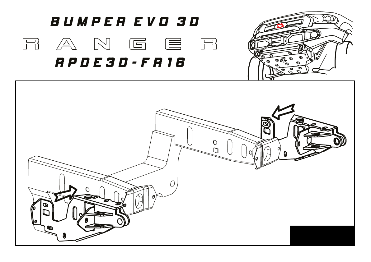
• Our bumper is designed to follow the original lines and aesthetics of
your vehicle.
• Your vehicles approach angle will be improved dramatically and also
provide you with recovery points and increased vehicle protection.
• Our modular system allows you to replace parts individually.
• We do not cut the original plastic bumper, this it can be stored and
reinstalled at any time.
Before commencing with the installation it is important that you read
and understand these installation instructions. If you need any technical
adviceplease contact you closest Rhino 4x4 dealer or contact us via
www.rhino4x4.com.au/contacts
Attention
DO NOT attach VFPS to the vehicle using any
fixing points not intended for this purpose.
DO NOT use this product on any other vehicle
make or model, other than those specified.
DO NOT remove the warning labels or Rhino
4x4 logo from the VFPS.
DO NOT modify the VFPS in any way.
STEP 1
Remove plastic facia, plastic facia retainer clips at front
edge of guard, steel bumper beam and front stone shield.
Remove the brackets from the wheel arch liners and the
two that hold the mid lower of the facia.
Plastic air deflectors can also be trimmed or removed if
preferred.
STEP 2
Locate the main chassis brackets as per image.
STEP 3
FASTENING BOLTS
zOriginal Bolt 04
aEX 12 1.25 x 50 04
bWasher D6 04
cPlate with 2 nuts 12 1.25 02
Insert the original front chassis bolts in new bracket
Insert the bracket with welded nuts into the chassis and fasten using the M10 bolts.
NOTE - It is best to insert bracket, hold front hole in position by inserting screwdriver all the way through chassis, then lift the rear
hole into position using screw driver through the front hole. Then remove screw driver through chassis and insert front bolt.
WINCH ASSEMBLY
FASTENING BOLTS
dSelf Drilling T1 ½” 12
eEX 6 1.00 x 15 12
fWasher D6 16
gNut 6 6 - 1.00 08
STEP 4
NOTE - Your fog lamps will already be installed however some times its easy to get to mounting bolts
if you remove the light housings.
STEP 5
FASTENING BOLTS
hAR 10 1.50 x 30 08
iEX 6 1.00 x 15 08
jWasher D6 08
NOTE - The next steps can be done either on or off the car
Locate winch cradle
Locate and loosely fasten wings to cradle and lower mid
section
Now is a good time to install Adaptive cruise
radar sensor if optioned. Please turn to options
page for further details on radar sensor mounting.
STEP 6
FASTENING BOLTS
hAR 10 1.50 x 30 04
iEX 6 1.00 x 15 04
jWasher D6 04
NOTE - If optioned now is a good time to install fairleed, and winch. See winch install details in the options section.
After winch install if optioned, place mid top into position and fasten using the two M10 bolts on both sides.
FASTENING BOLTS
hAR 10 1.50 x 30 04
iWasher D10 08
jNut D10 1.5 08
mAR 10 1.50 x 20 04
FASTENING BOLTS
kEX 12 1.25 x 30 06
bWasher D13 12
lNut D12 1.25 06
STEP 7
If assembled off vehicle you can now mount assembly to vehicle.
NOTE - rear cradle bolts are inserted from under chassis
bracket. The front two on each side are inserted from top.
Locate and loosely fasten the wing support brackets.
Once fully in position use adjustment in chassis brackets
and wing supports to align to lower edge of lights and
bottom of front guards. Ensuer rubber seals are inserted beside
lights and then along the front edge of lights.
Once aligned tighten all bolts.
STEP 8
FASTENING BOLTS
hAR 10 1.50 x 30 02
nCountersunk screw
8 1.25 x 25 04
oCountersunk screw
10 1.50 x 30 02
pThreaded Plate 10 1.50 04
qKey with Nut 8 1.25 04
zOriginal Bolt
Locate and fasten front and then rear bash plate.
STEP 9
PX RANGER MK2 GRILL
The Rhino4x4 Evolution 3D front winch bar for the Ranger
MK2 is designed to fit both the standard ranger grill and
also the Ford Everest Grill. The Everest grill will fit with
no modification. The standard Ranger grill will just need
the lower section trimmed off. This is an easy task and
provides a great finish.
GRILL CUT
The image on the right displays where the grill is
trimmed. There is an existing radius that runs along the
lower section of the grill from one side to the other. This
line is followed.
1. Place grill on ground front side up
2. Using a fine cutting disc on an angle grinder cut along the
radius splitting it in half from one side to the other.
3. Turn the grill over ensuring the front sits on something
that will not mark it. On the rear there is another layer to
cut through. You will see the line to cut as you would have
penetrated areas from the front cut. Finish the cut from the
rear. Its best to cut the rear a little higher than the front so that
you cannot see that layer from the front.
NOTE: Ensure you do not cut through to the front in this step.
4. Sit the grill in place. You will then see where you need to
adjust the cut depending on your final bar install position. Aim
for a minimum of 5mm gap between bar and grill to prevent
paint rubbing during body flex. You can achieve this by using
the side of the cutting disc.
5. Once you are happy with your final shape, finish off the edge
using sand paper on a block to get a nice smooth and uniform
finish. If your grill is chrome, make any sanding/filing motions
from front of grill to rear to ensure you don’t separate the
chrome from the plastic grill. Also be careful as chrome edge
can be sharp.
STEP 9
NUMBER PLATE BRACKET TECH PACK KIT
OPTIONAL
FASTENING KIT
EX 6 1.00 x 15 09
Washer D6 18
Nut 6 - 1.00 09
FASTENING KIT
EX 6 1.00 x 15 06
Washer D6 12
Nut 6 - 1.00 06
Locate number plate bracket to existing
holes under leading edge of bar top mid
as per image.
After mounting radar sensor adjust to vertical. This should
suffice but if error after test drive,
angle might need to be adjusted
again to ensure correct operation.
WINCH ASSEMBLY
OPTIONAL
Install winch as per winch manufacturers specifications.
Great Job! FINISH
Once you have finished bar install ensure fog lamps, parking sensors and radar
sensor are plugged in.
NOTE - Ensure you road test vehicle to confirm operation of radar sensor.
Adjustment of radar sensor angle may be required if error on dash.
FASTENING BOLTS gAR 10-1.5 x 20 mGrill Bracket 2u
bWasher D10 hAR 6-1.00 x 20 nWasher D8 4u
cNut 10-1.5 i¾ x 1/8Set Screw oAR 8-1.25 x 30 4u
dEXAG 6-100 x 15 jAllen Button 8-1.25 x 20 p1 Threaded plate 10-1.5 4u
eWasher D6 kPlate with nut 8-1.25 p2 Threaded plate 10-1.5 2u
fNut 6-100 lCountersunk screw 10-1.5 x 30 p3 Threaded plate 8-1.25 2u
PARTS CHECK LIST
C
H
E
C
K
L
I
S
T
with a couple of rubber joints
optional optional optional
RPDE3DCH-FR16
RPDE3DBF-FR16
NUMBER PLATE
BRACKET
RPDE3DCC-FR16
INSTRUCTION MANUAL
RPDE3DSP-FR16
RPDE3DB-FR16
BOLTS KIT
LED LIGHT SETTECH PACK KIT FOGLIGHT
COVER
RPDE3DSF-FR16
RPDE3DPC-FR16
RPDE3DCD-FR16
RPDE3DP-FR16
I + D // R & L
I + D // R & LI + D // R & L
I + D // R & L
I + D // R & L
Factory 2 / 25 Progress Street
Mornington VIC 3931 Australia
[email protected]u
www.rhino4x4.com.au
TOUGH
NEVER LOOKED
SO GOOD

Other manuals for EVO 3D

3

This manual suits for next models

1

Other RHINO Automobile Accessories manuals

RHINO VSDS-RVM4.3 User manual

RHINO

RHINO VSDS-RVM4.3 User manual

RHINO EVO 3D User manual

RHINO

RHINO EVO 3D User manual

RHINO IM007 User manual

RHINO

RHINO IM007 User manual

RHINO RC456 User manual

RHINO

RHINO RC456 User manual

RHINO 2500 Series User manual

RHINO

RHINO 2500 Series User manual

RHINO EVO 3D User manual

RHINO

RHINO EVO 3D User manual

RHINO EVO 3D User manual

RHINO

RHINO EVO 3D User manual

RHINO Drive360 User manual

RHINO

RHINO Drive360 User manual

RHINO FPA User manual

RHINO

RHINO FPA User manual

RHINO RLCP22 User manual

RHINO

RHINO RLCP22 User manual

Popular Automobile Accessories manuals by other brands

Hama Easy Snap operating instructions

Hama

Hama Easy Snap operating instructions

EAL LAS 10112 operating instructions

EAL

EAL LAS 10112 operating instructions

M7 R56 installation guide

M7

M7 R56 installation guide

Jaeger 21060578 Fitting instructions

Jaeger

Jaeger 21060578 Fitting instructions

Subaru J2010FL020 installation manual

Subaru

Subaru J2010FL020 installation manual

Intermec Oracle-Ready CK31 instruction manual

Intermec

Intermec Oracle-Ready CK31 instruction manual

Kuda 043190 installation instructions

Kuda

Kuda 043190 installation instructions

Techart Front Spoiler I Mounting instructions

Techart

Techart Front Spoiler I Mounting instructions

Sony PEGA-CC5 operating instructions

Sony

Sony PEGA-CC5 operating instructions

DV8 Gladiator RBGL-03 installation manual

DV8

DV8 Gladiator RBGL-03 installation manual

MAD HV-198350 Fitting instructions

MAD

MAD HV-198350 Fitting instructions

Toyota Bluetooth SWC owner's manual

Toyota

Toyota Bluetooth SWC owner's manual

Thule 1285 Fitting instructions

Thule

Thule 1285 Fitting instructions

TJM 081SBRKIT46H Fitting instructions

TJM

TJM 081SBRKIT46H Fitting instructions

Choetech TC0008 user manual

Choetech

Choetech TC0008 user manual

Atera SIGNO 044 055 User information

Atera

Atera SIGNO 044 055 User information

Cruz 940-223 Assembly instructions

Cruz

Cruz 940-223 Assembly instructions

Brodit ProClip 853241 installation instructions

Brodit

Brodit ProClip 853241 installation instructions

manuals.online logo
manuals.online logoBrands
  • About & Mission
  • Contact us
  • Privacy Policy
  • Terms and Conditions

Copyright 2025 Manuals.Online. All Rights Reserved.