manuals.online logo
Brands
  1. Home
  2. •
  3. Brands
  4. •
  5. RHINO
  6. •
  7. Automobile Accessories
  8. •
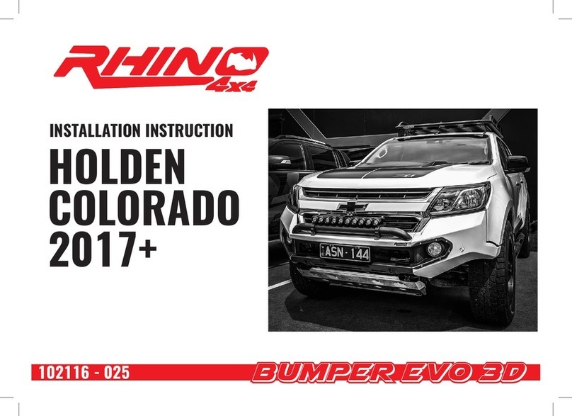
  9. RHINO EVO 3D User manual

RHINO EVO 3D User manual

Other manuals for EVO 3D

3

This manual suits for next models

1

Other RHINO Automobile Accessories manuals

RHINO EVO 3D User manual

RHINO

RHINO EVO 3D User manual

RHINO RLCP22 User manual

RHINO

RHINO RLCP22 User manual

RHINO FPA User manual

RHINO

RHINO FPA User manual

RHINO EVO 3D User manual

RHINO

RHINO EVO 3D User manual

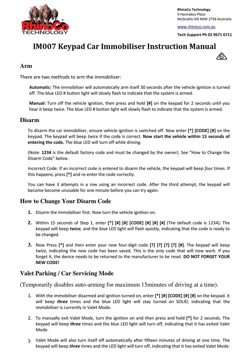
RHINO IM007 User manual

RHINO

RHINO IM007 User manual

RHINO RC456 User manual

RHINO

RHINO RC456 User manual

RHINO EVO 3D Service manual

RHINO

RHINO EVO 3D Service manual

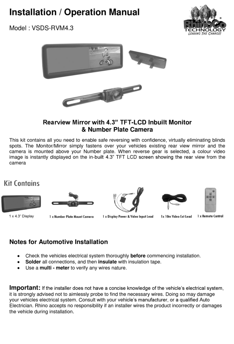
RHINO VSDS-RVM4.3 User manual

RHINO

RHINO VSDS-RVM4.3 User manual

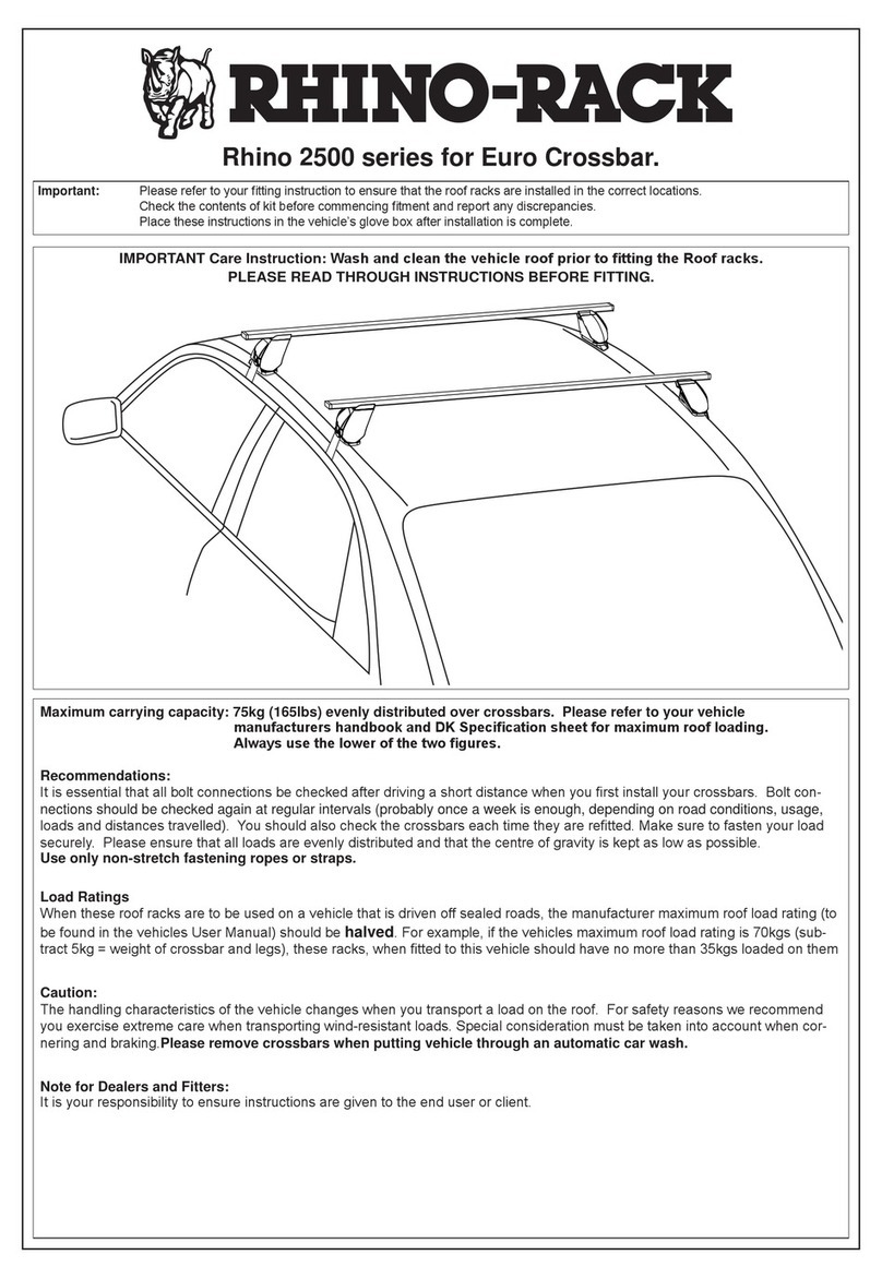
RHINO 2500 Series User manual

RHINO

RHINO 2500 Series User manual

RHINO Drive360 User manual

RHINO

RHINO Drive360 User manual

Popular Automobile Accessories manuals by other brands

Magneti Marelli AC161 Installation instruction

Magneti Marelli

Magneti Marelli AC161 Installation instruction

FDI uEZ GUI Start here

FDI

FDI uEZ GUI Start here

JCROffroad JT Install instructions

JCROffroad

JCROffroad JT Install instructions

Rostra VOXXElectronics 250-1930 owner's guide

Rostra

Rostra VOXXElectronics 250-1930 owner's guide

TOP VEHICLE TECH GR3FORD5 installation manual

TOP VEHICLE TECH

TOP VEHICLE TECH GR3FORD5 installation manual

Safe Fleet PRIME DESIGN AR-2000-BLK manual

Safe Fleet

Safe Fleet PRIME DESIGN AR-2000-BLK manual

Skoda Fabia Combi 5J Fitting instructions

Skoda

Skoda Fabia Combi 5J Fitting instructions

Camcar 40077 Al Mounting instructions

Camcar

Camcar 40077 Al Mounting instructions

Camcar 40089 AL Mounting instructions

Camcar

Camcar 40089 AL Mounting instructions

Impac Tradesman 2000 installation manual

Impac

Impac Tradesman 2000 installation manual

DVB OFFROAD BRSB-01 installation manual

DVB

DVB OFFROAD BRSB-01 installation manual

Safari Snorkel SS385HF installation guide

Safari Snorkel

Safari Snorkel SS385HF installation guide

ULTIMATE SPEED 279746 Assembly and Safety Advice

ULTIMATE SPEED

ULTIMATE SPEED 279746 Assembly and Safety Advice

SSV Works DF-F65 manual

SSV Works

SSV Works DF-F65 manual

ULTIMATE SPEED CARBON Assembly and Safety Advice

ULTIMATE SPEED

ULTIMATE SPEED CARBON Assembly and Safety Advice

Witter F174 Fitting instructions

Witter

Witter F174 Fitting instructions

WeatherTech No-Drill installation instructions

WeatherTech

WeatherTech No-Drill installation instructions

TAUBENREUTHER 1-336050 Installation instruction

TAUBENREUTHER

TAUBENREUTHER 1-336050 Installation instruction

manuals.online logo
manuals.online logoBrands
  • About & Mission
  • Contact us
  • Privacy Policy
  • Terms and Conditions

Copyright 2025 Manuals.Online. All Rights Reserved.

Fitting Instructions
www.rhino4x4.com.au
1
Next Gen Ranger Bumper Evo 3D
Ph: 1300 885 841 | Email: [email protected] | Website: www.rhino4x4.com.au
Please Read Prior to Commencing the Install
www.rhino4x4.com.au
2
Thank-you for choosing to equip your vehicle
with our product. Following are some of the
great features that our bar includes:
- Our bar is designed to follow the original
lines and aesthetics of your vehicle.
- The approach angle of your vehicle will
be increased dramatically, while
increasing protection.
- Our modular system allows you to replace
parts individually.
- We do not cut the original plastic bumper,
thus it can be reinstalled if required.
Before commencing the installation it is
important that your read and understand these
installation instructions, if you require any
technical advice please contact your closest
Rhino 4x4 dealer.
Welcome to the Rhino 4x4 team!
- Do not attach VFPS vehicle using any
fixing points not intended for this purpose.
- Do not use this product on any other
vehicle make or model, other than those
specified.
- Do not remove the warning labels or
Rhino 4x4 logo from the VFPS.
- Do not modify the VFPS in any way.
www.rhino4x4.com.au
3
Block 1: Preparing the Chassis
1.
2.
3.
4.
5.
Assemble all parts displayed
in the table and image.
Release all clips from the plastic cover.
Remove the plastic cover, pulling it out
from under the air intake.
Release plastic clips from the inside of
the flares.
Undo the 2 x T25 Torx screws on the
underneath of the bumper corners.
Remove the 2 x 8mm hex bolts from the
top of the grill.
www.rhino4x4.com.au
4
6.
7.
8.
9.
10.
Continue to remove all remaining bolts
from the underside of the bumper.
Remove the 2 x 10mm hex bolts and 3
plastic clips seen behind the back of the
grille.
Block 1: Preparing the Chassis
Remove the wheel arch liner cover.
Remove the 3 x 10mm hex bolts inside
the cover.
This is easiest with a 90 degree impact
wrench.
Unplug the camera from the top of the
grille, then release the 2 clips.
www.rhino4x4.com.au
5
11.
12.
13.
14.
15.
Clamp the headlight washer hose and
unplug the line.
Remove the camera wire from the
location tab slot.
Block 1: Preparing the Chassis
Disconnect the main harness plug.
Pull back the front of the flare slightly.
There are clips that will release when
pulled.
Using the access hole in the wheel arch liner from step
8, pry the 2 flare clips allowing it to be removed further.
Then unplug the sensors in the flares.
www.rhino4x4.com.au
6
16.
17.
18.
19.
20.
Pull forwards and downwards on the bumper to now remove it.
If stuck, the locational pins and clips can be accessed through the
access hole in the wheel arch.
Once the bumper is off, the grille can be removed.
Remove the polystyrene bumper support
from the lower cross member.
Block 1: Preparing the Chassis
Remove the bolts from the lower cross member,
then remove the cross member including the radar.
Remove the factory bash plate, there are 4 x 15mm
hex bolts.
Remove the factory recovery points. The intercooler
will need to be temporarily supported by cable ties.
Remove the bumper support
bracket on both sides.
www.rhino4x4.com.au
7
21.
22.
23.
24.
25.
It may be required to trim the plastic on
the radiator surround for clearance.
Block 1: Preparing the Chassis
Trim the plastic in front of the radiator along
the lines shown.
Reposition the horns to the position shown.
For wiring the fog lights, unplug the 16 pin plug.
Pin 6 is wired to the DRL/Parker wire (brown)
Pin 7 is wired to the indicator wire (yellow)
This diagram may help in wiring the
fog lights.
Pin 7
Pin 6
Indicator Wire
DRL Wire
Earth
Fog Wire
www.rhino4x4.com.au
8
26.
27.
28.
29.
30.Pry the sensor housings from the factory
bumper and install into the wings using
double sided tape and sikaflex.
Block 2: Installing the Front Bar
Attach the Rhino 4x4 recovery points to the
underside of the chassis, leaving some
movement at this stage.
Attach the intercooler support brackets loosely to the
winch cradle.
Attach the winch cradle to the recovery point
brackets using the factory bolts, take care to
align the intercooler mounts with the support
brackets.
The high beam trigger location is vehicle dependend. For vehicles with the factory
switch panel see pages 58-59 via the link below, alternatively see pages 73-77.
Additionaly, see Appendix 1.0 for Trailmax wiring harness details.
https://www.ford.com.au/content/dam/Ford/website-assets/ap/au/owner/vehicle-support/body-equipment-
manuals/2022-TRA-Base-BEMM-Publishable-25-07-2022.pdf
www.rhino4x4.com.au
9
31.
32.
33.
34.
35.
Install the bash plate support bracket.
Trim the factory flare to align with the
quarter panel, as displayed.
Block 2: Installing the Front Bar
The sensors will be re-mounted to the bar
using the provided sensor clips. The sensor
housing may require trimming to allow
installation in the direction shown.
The outermost sensor clips will have to be mounted
to the flare extensions prior to the extensions being
installed.
After the housing is attached and fitment has been
checked, remove the sensor as it must be inserted
through the wing.
www.rhino4x4.com.au
10
36.
37.
38.
39.
40.
If a light bar is optioned, before installing the
upper mid it is recommended to mount the
light bar. This can be completed using the
provided mounting brackets in the kit.
Then proceed to install the upper mid section.
Correct the front to back and left to right
alignment of the bar, then fasten the recovery
point brackets and winch cradle bolts tightly.
Block 2: Installing the Front Bar
Install the infills on top of the wings prior to
installing the wings. There is no need to over
tighten these are it may require later adjustment.
Install the rubber strip along the top of the wing,
this also must be completed prior to installing the
wing.
The wings can now be mounted to the winch cradle.
This should be tightened such that movement for
alignment is still possible.