Pag. 5 di 8
INSTALLAZIONE DELLA CASSETTA PORTANTE
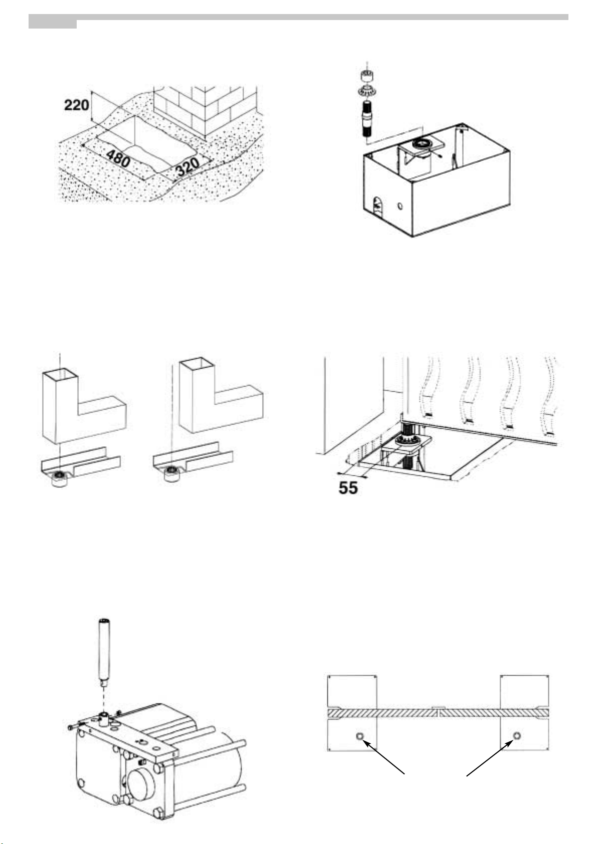
È necessario eseguire uno scavo di fondazione le cui dimensioni siano
come quelle indicate in fig.2. Per evitare eventuali cedimenti del piano di scavo è
consigliabile consolidare la superficie di appoggio della cassetta con del cemento a
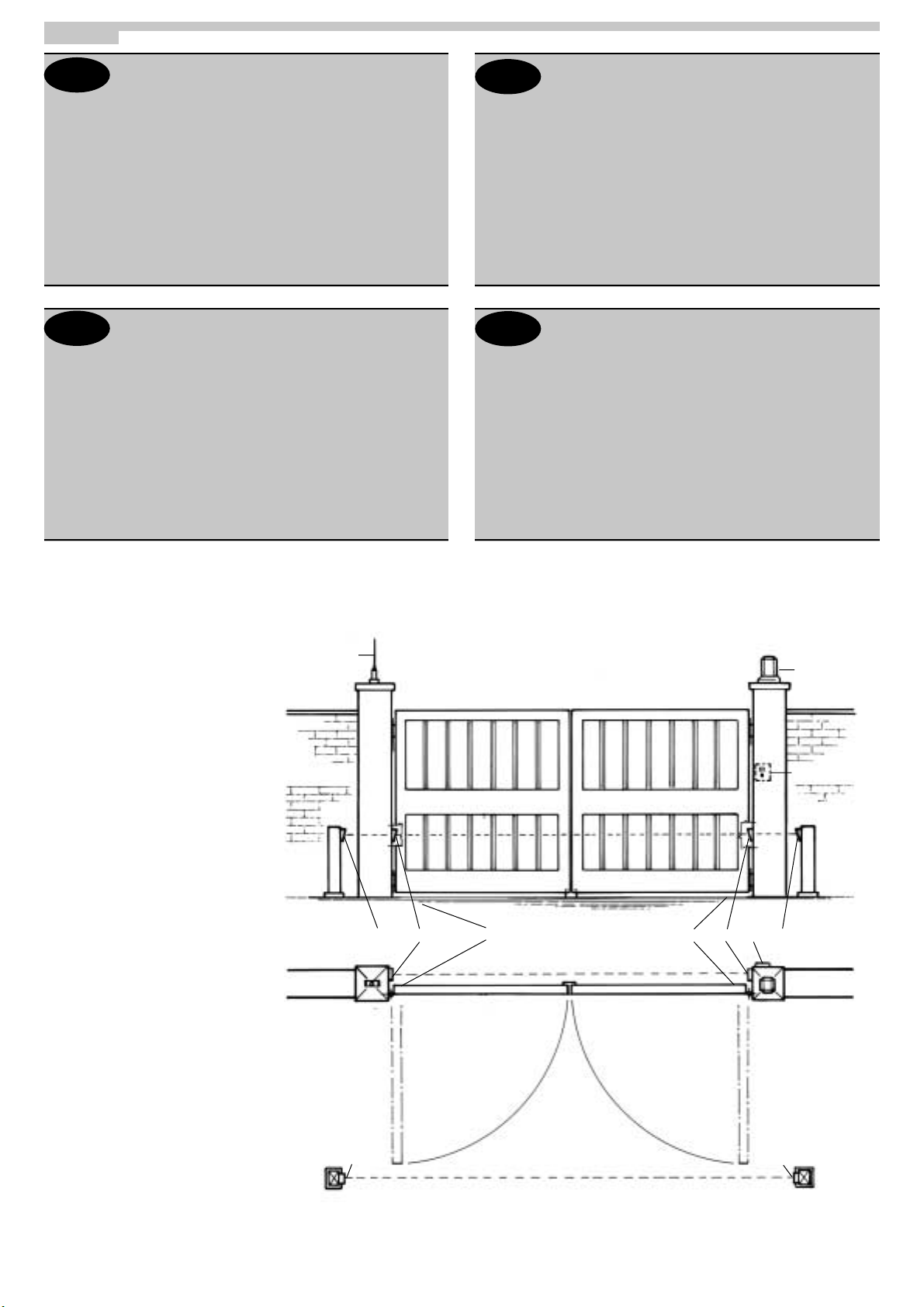
presa rapida. La cassetta portante va posizionata in piano nello scavo. Assicurarsi che il
centro del pignone sia perfettamente allineato con l’asse di rotazione dell’anta (Fig. 4 .
MONTAGGIO DELL’ANTA
Prima di installare l’anta assicurarsi che il cemento nello scavo di fondazione abbia fatto
presa.
A - Costruire la staffa gida del cancello procedendo come segue:
- reperire un profilato ad U.
- posizionare la boccola sul profilato riferendosi all’asse di rotazione dell’anta (fig. 4
- ruotare la boccola scanalata in modo tale da far coincidere un vano della scanalatura
con l’asse del profilato.
- saldare con cura la boccola al profilato (fig. 4
- chiudere il profilato ad U, dal lato del pilastro, saldando una piastra
B - Lubrificare il pignone della cassetta portante con del grasso
C - Inserire la staffa guida sul pignone (fig. 4
D - Appoggiare l’anta del cancello sulla staffa guida e collegarla alla cerniera superiore
È assolutamente da evitare di saldare l’anta del cancello alla staffa guida o direttamente
sulla boccola scanalata.
INSTALLAZIONE DELL’OPERATORE
- Posizionare l’anta a fine corsa di apertura.
- Introdurre la boccola scanalata di giunzione sul pignone della cessetta portante.
- Introdurre l’operatore all’interno della cassetta portante ed accoppiare il pignone
dell’operatore con il pignone della cassetta utilizzando la boccola scanalata di
giunzione.
- Sbloccare l’operatore e chiudere/aprire manualmente l’anta per verificare il corretto
funzionamento del sistema.
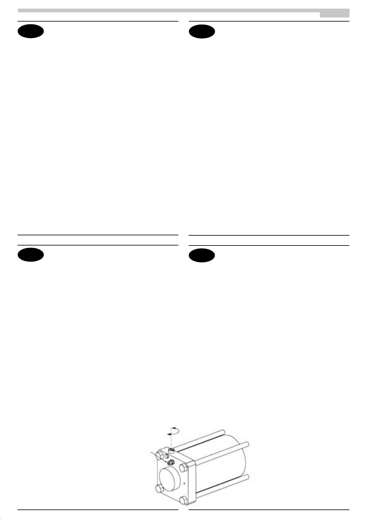
- Per limitare la corsa del cancello è possibile utilizzare le viti dedicate alla regolazione
della corsa di apertura e di chiusura. Ognuna di loro toglie da 0° a 30° alla corsa. Più si
avvitano in senso orario più si limita la corsa del cancello.
INSTALLATION DU BOÎTIER PORTANT
Creuser des fondations selon les dimensions indiquées en fig.2.
Pour éviter tout effondrement des fondations, il est conseillé de renforcer la surface
d’appui du boîtier avec du ciment à prise rapide.
Le boîtier est placé dans les fondations.
S’assurer que le centre du pignon est parfaitement aligné avec l’axe de rotation du
vantail (Fig. 4 .
MONTAGE DU VANTAIL
Avant de monter le vantail, s’assurer que le ciment des fondations a bien pris.
A - Construire le rail de guidage du portail en procédant comme suit :
- se munir d’un profilé en U.
- positionner l’essieu sur le profilé par rapport à l’axe de rotation du vantail (fig. 4
- tourner l’essieu rainuré de façon à aligner un logement de rainure avec l’axe du profilé.
- souder soigneusement l’essieu au profilé (fig. 4
- fermer le profilé en U, du côté du pilier en soudant une plaque
B – Lubrifier le pignon du boîtier portant avec de la graisse
C – Introduire le rail de guidage sur le pignon (fig. 4
D – Appuyer le vantail du portail sur le rail de guidage et le fixer à la charnière
supérieure.
Attention, ne pas souder le vantail du portail au rail de guidage ou directement sur
l’essieu rainuré.
INSTALLATION DE L’OPÉRATEUR
- Positionner le vantail en fin de course d’ouverture.
- Introduire l’essieu rainuré d’assemblage sur le pignon du boîtier portant.
- Introduire l’opérateur à l’intérieur du boîtier portant et assembler le pignon de
l’opérateur au pignon du boîtier au moyen de l’essieu rainuré d’assemblage.
- Débloquer l’opérateur et fermer/ouvrir à la main le vantail pour vérifier le bon
fonctionnement du système.
- Il est possible de limiter la course de l’opérateur au moyen des vis de réglage de la
course. Chacune d’elles réduit la course de 0° à 30°. En vissant dans le sens des
aiguilles d’une montre, on réduit la course de l’opérateur.
INSTALLATION OF THE SUPPORT BOX
It is necessary to excavate foundations of the dimensions indicated in fig.
2.
To avoid any risk of settling in the foundations it is recommended that the surface
bearing the support box be consolidated using quick-drying cement.
The support box must be set level in the excavated area. Ensure that the centre of the
pinion is perfectly aligned with the axis of rotation of the door (Fig. 4 .
FITTING THE DOOR
Before installing the door, ensure that the cement in the foundations has hardened.
A - Form the gate guide slot as follows:
- take a channel.
- position the bush on the channel, using the axis of rotation of the door as a reference
(fig. 4
- turn the grooved bush so that one groove coincides with the axis of the channel.
- carefully weld the bush to the channel (fig. 4
- close the channel on the pillar side, by welding on a plate
B - Lubricate the support box pinion using grease
C - Insert the guide slot on the pinion (fig. 4
D - Rest the door of the gate on the guide slot and connect it to the top hinge
Under no circumstances must the door of the gate be welded to the guide slot or directly
to the grooved bush.
FITTING THE OPERATOR
- Open the door to its fullest extent.
- Insert the grooved connection bush on the support
box pinion.
- Insert the operator into the support box and couple
the pinion on the operator to the pinion
on the box using the grooved
connection bush.
- Unlock the operator and open/close
the door manually to check the system
is operating correctly.
- To limit the stroke of the operator, use the stroke
adjustment screws. Each of these screws reduces
the stroke by between 0° and 30°.
The more they are turned in a clockwise direction, the
more the stroke of the operator is limited.
MONTAGE DES TRAGENDEN GEHÄUSES
Hierfür ist es erforderlich einen Schacht in den in Abb. 2 dargestellten
Abmessungen auszuführen. Um das Setzen des Schachts zu verhindern, sollte die
Auflage des Gehäuses mit Schnellzement konsolidiert werden.
Das tragende Gehäuse muß eben im Schacht liegen.
Sicherstellen, daß die Ritzelmitte perfekt mit der Drehachse des Torflügels (Abb. 4
ausgerichtet ist.
MONTAGE DES TORFLÜGELS
Vor der Montage des Torflügels sicherstellen, daß der Zement im Schacht abgebunden
ist.
A - Die Torführung wie folgt einbauen:
- ein U-Profil nehmen.
- die Buchse auf dem Profil entsprechend der Drehachse des Tors (Abb.4 fluchten.
- die Nutbuchse so eindrehen, daß eine Nute mit der Profilachse ausgerichtet ist.
- vorsichtig die Buchse an das Profil (Abb.4 schweißen.
- zum Schließen des U-Profils eine Platte an der Säuleseite anschweißen.
B - Das Ritzel des tragenden Gehäuses fetten
C - Die Führung in das Ritzel (Abb.4 einsetzen.
D - Den Torflügel an die Führung anlegen und mit dem oberen Scharnier verbinden.
Den Torflügel nicht an die Führung oder direkt auf die Nutbuchse schweißen.
MONTAGE DES ANTRIEBS
- Den Torflügel bis zum Anschlag öffnen.
- Die Anschlußbuchse in das Ritzel des
tragenden Gehäuses einführen.
- Den Antrieb in das tragende Gehäuse
einlegen und mit der Nutbuchse das
Antriebsritzel mit dem Gehäuseritzel
paaren.
- Um die Funktionstüchtigkeit des
Systems sicherzustellen, den Antrieb
entriegeln und von Hand den Torflügel
öffnen/schließen,.
- Um den Hubweg des Antriebs
einzustellen, können die
entsprechenden Schrauben
verwendet werden. Jede Schraube
reduziert den Hubweg um 0° bis 30°.
Je mehr diese im Uhrzeigersinn
eingeschraubt werden, desto mehr
reduziert sich der Antriebsweg.
I
D
F
GB
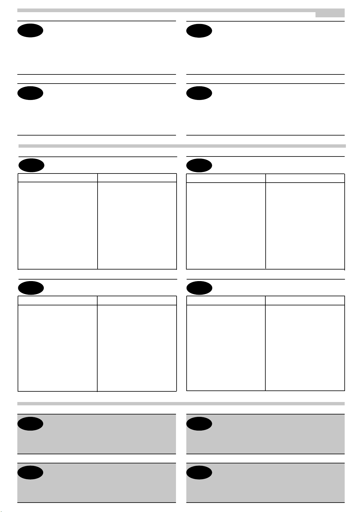
REGOLAZIONE CORSA
RÉGLAGE DE LA COURSE
STROKE ADJUSTMENT
HUBEINSTELLUNG
VITE DI SPURGO
VIS DE PURGE
BLEEDER SCREW
ENTLÜFTUNGSSCHRAUBE
Fig. 8