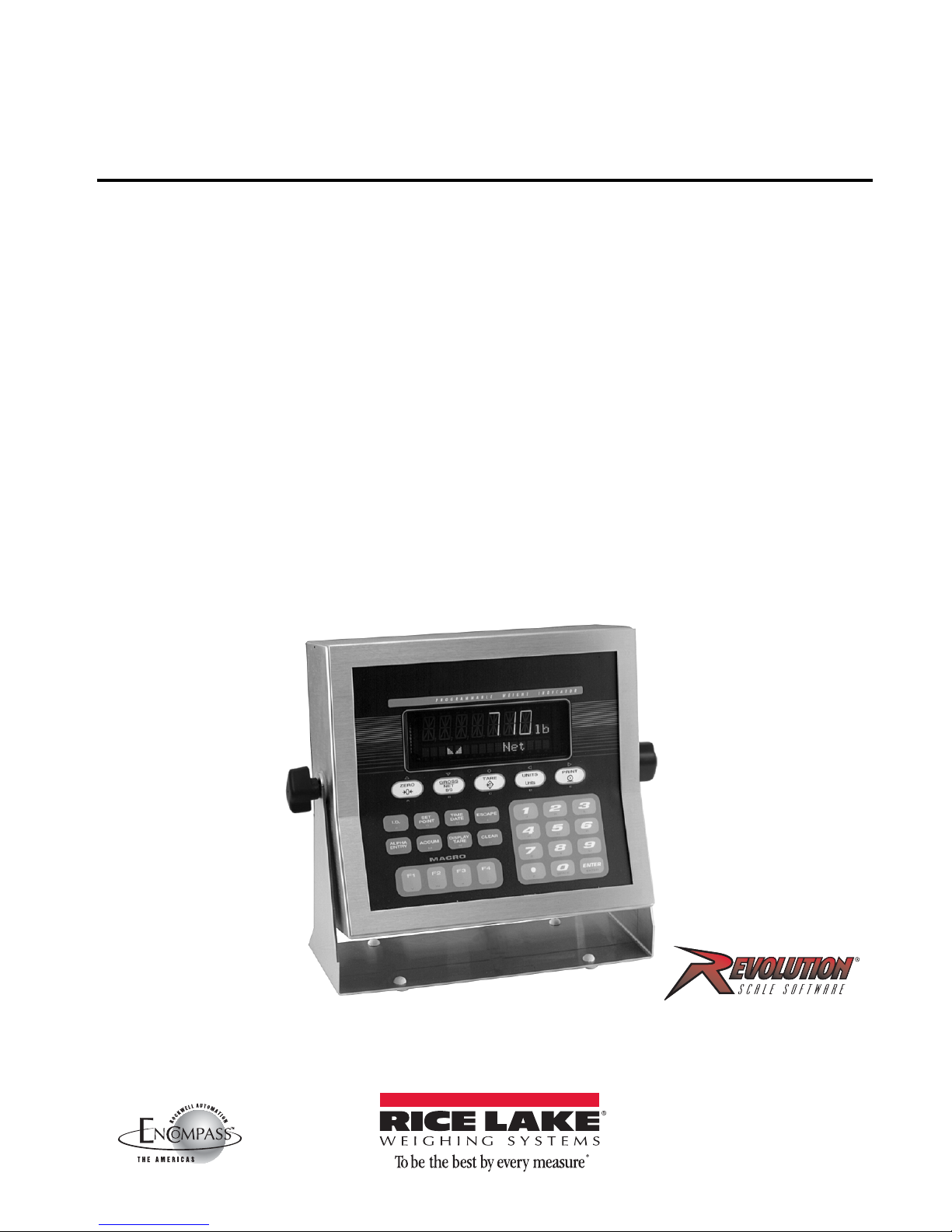
Introduction 3
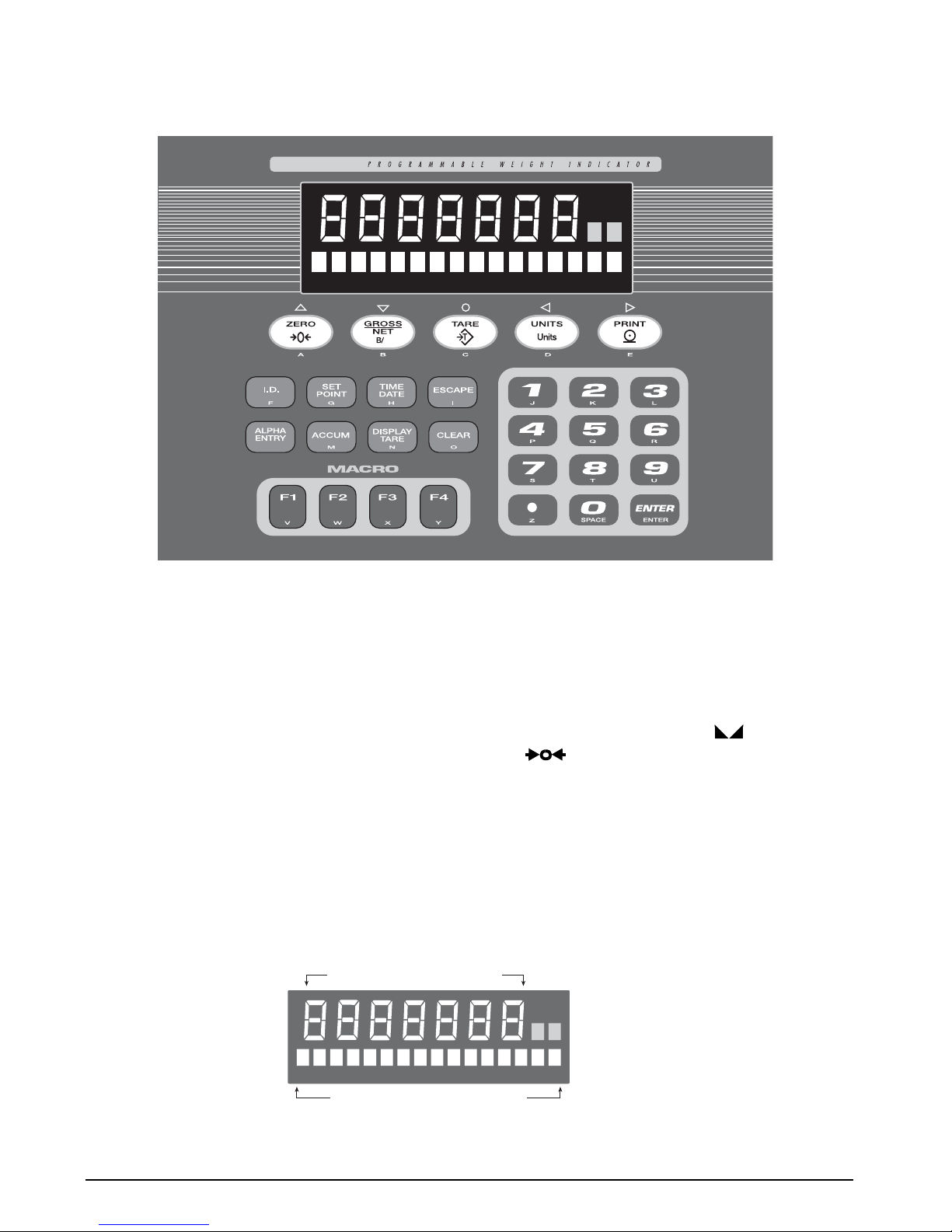
1.3 Indicator Operations
Basic IQ plus 710 operations are summarized below:
1.3.1 Toggle Gross/Net Mode
Press the GROSS/NET key to switch the display mode
from gross to net, or from net to gross. If a tare value
has been entered or acquired, the net value is the gross
weight minus the tare. If no tare has been entered or
acquired, the display remains in gross mode.
Gross mode is indicated by the word Gross (or
Brutto in OIML mode) on the secondary display; net
mode is indicated by the word Net.
1.3.2 Toggle Units
Press the UNITS key to switch between primary and
secondary units. The units identifier is shown to the
right of the primary display. Troy ounces and troy
pounds are indicated by the word troy on the
secondary display.
1.3.3 Zero Scale
1. In gross mode, remove all weight from the
scale and wait for the standstill annunciator
().
2. Press the ZERO key. The center of zero
() annunciator lights to indicate the
scale is zeroed.
1.3.4 Acquire Tare
1. Place container on scale and wait for the
standstill annunciator ( ).
2. Press the TARE key to acquire the tare weight
of the container.
3. Display shifts to net weight and shows the
word Net on the secondary display.
To display the current tare value, press the DISPLAY
TARE key.
1.3.5 Remove Stored Tare Value
1. Remove all weight from the scale and wait for
the standstill annunciator ( ).
2. Press the TARE key (or, in OIML mode, the
ZERO key). Display shifts to gross weight and
shows the word Gross on the secondary
display.
1.3.6 Print Ticket
1. Wait for the standstill annunciator ( ).
2. Press the PRINT key to send data to the serial
port.
1.3.7 Display or Change Time and Date
To display the date, press the TIME/DATE key once;
press TIME/DATE a second time to display the time.
To set the date, press the TIME/DATE key once. Use the
numeric keypad to enter the date, then press the
ENTER key. The date must be entered in the date
format configured for the indicator: MMDDYY,
DDMMYY, or YYMMDD.
To set the time, press the TIME/DATE key twice. Use
the numeric keypad to enter the time in 24-hour
format, then press the ENTER key.
1.3.8 Display or Change Setpoint Value
To display a setpoint value, use the numeric keypad to
enter the setpoint number, then press the SETPOINT
key. Or, you can display a setpoint value by pressing
the SETPOINT key a number of times equal to the
setpoint number. For example, to display the value of
setpoint 4, press the SETPOINT key four times.
To change the setpoint value, display the current
value, then use the numeric keypad to enter the new
value and press the ENTER key.
NOTE: Some indicator configurations may not allow setpoint
values to be changed through the front panel or may require a
password to display or change the setpoint value.
1.3.9 Turn Setpoint On or Off
To turn a setpoint off at the front panel, use the
numeric keypad to enter the setpoint number, then
press the SETPOINT key (or, press the SETPOINT key a
number of times equal to the setpoint number). With
the correct setpoint displayed, press CLEAR to turn the
setpoint off.
To re-enable a setpoint on that has been turned off at
the front panel, press the SETPOINT key until the
correct setpoint is displayed, then press ENTER to turn
the setpoint back on.
NOTE: Some indicator configurations may not allow setpoints
to be turned off through the front panel or may require a
password to turn the setpoint on and off.
1.3.10 Display or Clear Accumulator
If the accumulator function is enabled, the current net
weight is added to the accumulator each time the
indicator performs a print operation.
• To display the current accumulator value,
press the ACCUM key.
• To clear the accumulator, press ACCUM to
show the current value, then press the CLEAR
key twice to reset the accumulator.