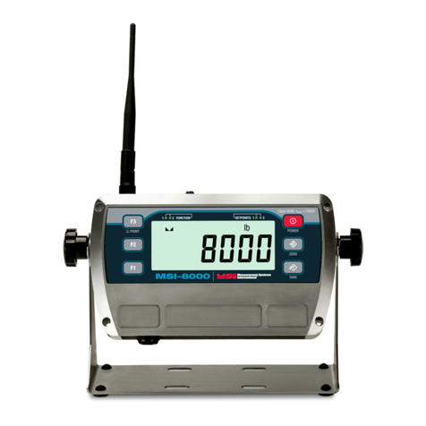
Rice Lake MSI-8000 User manual

MSI-8000
RF Remote Display
Technical Manual
PN 133063 Rev E

An ISO 9001 registered company
© Rice Lake Weighing Systems. All rights reserved.
Rice Lake Weighing Systems®is a registered trademark of
Rice Lake Weighing Systems.
All other brand or product names within this publication are trademarks or
registered trademarks of their respective companies.
All information contained within this publication is, to the best of our knowledge, complete
and accurate at the time of publication. Rice Lake Weighing Systems reserves the right to
make changes to the technology, features, specifications and design of the equipment
without notice.
The most current version of this publication, software, firmware and all other product
updates can be found on our website:
www.ricelake.com

Contents
Contents 1
© Rice Lake Weighing Systems. All rights reserved. Printed in the United States of America.
Specifications subject to change without notice.
Rice Lake Weighing Systems is an ISO 9001 registered company.
September 19, 2016
Technical training seminars are available through Rice Lake Weighing Systems.
Course descriptions and dates can be viewed at www.ricelake.com/training
or obtained by calling 715-234-9171 and asking for the training department.
1.0 Introduction..................................................................................................................................... 1
1.1 Features . . . . . . . . . . . . . . . . . . . . . . . . . . . . . . . . . . . . . . . . . . . . . . . . . . . . . . . . . . . . . . . . . . . . . . . . 1
1.2 Safety . . . . . . . . . . . . . . . . . . . . . . . . . . . . . . . . . . . . . . . . . . . . . . . . . . . . . . . . . . . . . . . . . . . . . . . . . . 2
1.3 Front Panel Description . . . . . . . . . . . . . . . . . . . . . . . . . . . . . . . . . . . . . . . . . . . . . . . . . . . . . . . . . . . . . 3
1.3.1 Key/Annunciator Functions . . . . . . . . . . . . . . . . . . . . . . . . . . . . . . . . . . . . . . . . . . . . . . . . . . . . . . . . . . . . 3
1.4 Options . . . . . . . . . . . . . . . . . . . . . . . . . . . . . . . . . . . . . . . . . . . . . . . . . . . . . . . . . . . . . . . . . . . . . . . . . 4
2.0 Operation......................................................................................................................................... 5
2.1 Power . . . . . . . . . . . . . . . . . . . . . . . . . . . . . . . . . . . . . . . . . . . . . . . . . . . . . . . . . . . . . . . . . . . . . . . . . . 5
2.2 Zero. . . . . . . . . . . . . . . . . . . . . . . . . . . . . . . . . . . . . . . . . . . . . . . . . . . . . . . . . . . . . . . . . . . . . . . . . . . . 5
2.3 Tare. . . . . . . . . . . . . . . . . . . . . . . . . . . . . . . . . . . . . . . . . . . . . . . . . . . . . . . . . . . . . . . . . . . . . . . . . . . . 5
3.0 Installation ...................................................................................................................................... 6
3.1 Unpacking . . . . . . . . . . . . . . . . . . . . . . . . . . . . . . . . . . . . . . . . . . . . . . . . . . . . . . . . . . . . . . . . . . . . . . . 6
3.2 Getting Started . . . . . . . . . . . . . . . . . . . . . . . . . . . . . . . . . . . . . . . . . . . . . . . . . . . . . . . . . . . . . . . . . . . 6
3.3 Battery. . . . . . . . . . . . . . . . . . . . . . . . . . . . . . . . . . . . . . . . . . . . . . . . . . . . . . . . . . . . . . . . . . . . . . . . . . 6
3.3.1 Charging. . . . . . . . . . . . . . . . . . . . . . . . . . . . . . . . . . . . . . . . . . . . . . . . . . . . . . . . . . . . . . . . . . . . . . . . . . 6
3.3.2 Battery Longevity . . . . . . . . . . . . . . . . . . . . . . . . . . . . . . . . . . . . . . . . . . . . . . . . . . . . . . . . . . . . . . . . . . . 7
4.0 Setup ............................................................................................................................................... 8
4.1 Setup Menu. . . . . . . . . . . . . . . . . . . . . . . . . . . . . . . . . . . . . . . . . . . . . . . . . . . . . . . . . . . . . . . . . . . . . . 8
4.2 Function Keys . . . . . . . . . . . . . . . . . . . . . . . . . . . . . . . . . . . . . . . . . . . . . . . . . . . . . . . . . . . . . . . . . . . . 9
4.2.1 Test . . . . . . . . . . . . . . . . . . . . . . . . . . . . . . . . . . . . . . . . . . . . . . . . . . . . . . . . . . . . . . . . . . . . . . . . . . . . . 9
4.2.2 Total . . . . . . . . . . . . . . . . . . . . . . . . . . . . . . . . . . . . . . . . . . . . . . . . . . . . . . . . . . . . . . . . . . . . . . . . . . . . 10
4.2.3 Net/Gross. . . . . . . . . . . . . . . . . . . . . . . . . . . . . . . . . . . . . . . . . . . . . . . . . . . . . . . . . . . . . . . . . . . . . . . . 10
4.2.4 Peak Hold. . . . . . . . . . . . . . . . . . . . . . . . . . . . . . . . . . . . . . . . . . . . . . . . . . . . . . . . . . . . . . . . . . . . . . . . 10
4.2.5 Units . . . . . . . . . . . . . . . . . . . . . . . . . . . . . . . . . . . . . . . . . . . . . . . . . . . . . . . . . . . . . . . . . . . . . . . . . . . . 10
4.2.6 Hi-Res . . . . . . . . . . . . . . . . . . . . . . . . . . . . . . . . . . . . . . . . . . . . . . . . . . . . . . . . . . . . . . . . . . . . . . . . . . 10
4.2.7 Print . . . . . . . . . . . . . . . . . . . . . . . . . . . . . . . . . . . . . . . . . . . . . . . . . . . . . . . . . . . . . . . . . . . . . . . . . . . . 11
4.2.8 Total Remote Devices. . . . . . . . . . . . . . . . . . . . . . . . . . . . . . . . . . . . . . . . . . . . . . . . . . . . . . . . . . . . . . . 11
4.3 Auto-Off. . . . . . . . . . . . . . . . . . . . . . . . . . . . . . . . . . . . . . . . . . . . . . . . . . . . . . . . . . . . . . . . . . . . . . . . 11
4.4 Setpoints . . . . . . . . . . . . . . . . . . . . . . . . . . . . . . . . . . . . . . . . . . . . . . . . . . . . . . . . . . . . . . . . . . . . . . . 11
4.5 Output . . . . . . . . . . . . . . . . . . . . . . . . . . . . . . . . . . . . . . . . . . . . . . . . . . . . . . . . . . . . . . . . . . . . . . . . . 12
4.6 Battery Life . . . . . . . . . . . . . . . . . . . . . . . . . . . . . . . . . . . . . . . . . . . . . . . . . . . . . . . . . . . . . . . . . . . . . 13
4.7 Standard . . . . . . . . . . . . . . . . . . . . . . . . . . . . . . . . . . . . . . . . . . . . . . . . . . . . . . . . . . . . . . . . . . . . . . 13
4.8 Remote Display Scale Setup . . . . . . . . . . . . . . . . . . . . . . . . . . . . . . . . . . . . . . . . . . . . . . . . . . . . . . . . 14
4.8.1 Filter Setup . . . . . . . . . . . . . . . . . . . . . . . . . . . . . . . . . . . . . . . . . . . . . . . . . . . . . . . . . . . . . . . . . . . . . . . 14
4.8.2 Total Mode . . . . . . . . . . . . . . . . . . . . . . . . . . . . . . . . . . . . . . . . . . . . . . . . . . . . . . . . . . . . . . . . . . . . . . . 15
5.0 Calibrating a Scale/Dyna-Link 2................................................................................................... 17
5.1 Initial Calibration. . . . . . . . . . . . . . . . . . . . . . . . . . . . . . . . . . . . . . . . . . . . . . . . . . . . . . . . . . . . . . . . . . 17
5.1.1 Routine Calibration . . . . . . . . . . . . . . . . . . . . . . . . . . . . . . . . . . . . . . . . . . . . . . . . . . . . . . . . . . . . . . . . . 17
5.1.2 C-Cal Calibration . . . . . . . . . . . . . . . . . . . . . . . . . . . . . . . . . . . . . . . . . . . . . . . . . . . . . . . . . . . . . . . . . . 18
5.2 Setup . . . . . . . . . . . . . . . . . . . . . . . . . . . . . . . . . . . . . . . . . . . . . . . . . . . . . . . . . . . . . . . . . . . . . . . . . 19
5.2.1 Standard Settings . . . . . . . . . . . . . . . . . . . . . . . . . . . . . . . . . . . . . . . . . . . . . . . . . . . . . . . . . . . . . . . . . . 20
5.3 Reset the Load Cell Calibration . . . . . . . . . . . . . . . . . . . . . . . . . . . . . . . . . . . . . . . . . . . . . . . . . . . . . . 20
6.0 Communications Setup................................................................................................................. 21
6.1 Communications Menu . . . . . . . . . . . . . . . . . . . . . . . . . . . . . . . . . . . . . . . . . . . . . . . . . . . . . . . . . . . . 21
6.2 Printer Setup . . . . . . . . . . . . . . . . . . . . . . . . . . . . . . . . . . . . . . . . . . . . . . . . . . . . . . . . . . . . . . . . . . . . 22
6.2.1 Control Modes . . . . . . . . . . . . . . . . . . . . . . . . . . . . . . . . . . . . . . . . . . . . . . . . . . . . . . . . . . . . . . . . . . . . 22
6.2.2 Standard Print Strings. . . . . . . . . . . . . . . . . . . . . . . . . . . . . . . . . . . . . . . . . . . . . . . . . . . . . . . . . . . . . . . 22
6.2.3 Printer Output Setup. . . . . . . . . . . . . . . . . . . . . . . . . . . . . . . . . . . . . . . . . . . . . . . . . . . . . . . . . . . . . . . . 23

2 MSI-8000 Remote Display
Rice Lake continually offers web-based video training on a growing selection
of product-related topics at no cost. Visit www.ricelake.com/webinars
6.3 RF Setup . . . . . . . . . . . . . . . . . . . . . . . . . . . . . . . . . . . . . . . . . . . . . . . . . . . . . . . . . . . . . . . . . . . . . . . 24
6.4 Setup Multiple Sensor Network . . . . . . . . . . . . . . . . . . . . . . . . . . . . . . . . . . . . . . . . . . . . . . . . . . . . . . 26
6.4.1 Set the Total Number of Load Cells . . . . . . . . . . . . . . . . . . . . . . . . . . . . . . . . . . . . . . . . . . . . . . . . . . . . 26
6.4.2 Scan Weight Inputs. . . . . . . . . . . . . . . . . . . . . . . . . . . . . . . . . . . . . . . . . . . . . . . . . . . . . . . . . . . . . . . . . 26
6.4.3 Load Totaling Settings . . . . . . . . . . . . . . . . . . . . . . . . . . . . . . . . . . . . . . . . . . . . . . . . . . . . . . . . . . . . . . 27
6.5 Scanless ID . . . . . . . . . . . . . . . . . . . . . . . . . . . . . . . . . . . . . . . . . . . . . . . . . . . . . . . . . . . . . . . . . . . . . 27
6.6 Zero and Tare in Multiple Load Cell Systems . . . . . . . . . . . . . . . . . . . . . . . . . . . . . . . . . . . . . . . . . . . . 28
6.7 Communications Port Hardware . . . . . . . . . . . . . . . . . . . . . . . . . . . . . . . . . . . . . . . . . . . . . . . . . . . . . 28
6.8 Relays . . . . . . . . . . . . . . . . . . . . . . . . . . . . . . . . . . . . . . . . . . . . . . . . . . . . . . . . . . . . . . . . . . . . . . . . . 30
6.8.1 Relay Options . . . . . . . . . . . . . . . . . . . . . . . . . . . . . . . . . . . . . . . . . . . . . . . . . . . . . . . . . . . . . . . . . . . . . 30
6.9 FCC Statement . . . . . . . . . . . . . . . . . . . . . . . . . . . . . . . . . . . . . . . . . . . . . . . . . . . . . . . . . . . . . . . . . . 31
6.10 International RF Certifications . . . . . . . . . . . . . . . . . . . . . . . . . . . . . . . . . . . . . . . . . . . . . . . . . . . . . . . 31
6.11 Antenna Options . . . . . . . . . . . . . . . . . . . . . . . . . . . . . . . . . . . . . . . . . . . . . . . . . . . . . . . . . . . . . . . . 32
6.11.1 Antennas Available for a MSI-8000HD . . . . . . . . . . . . . . . . . . . . . . . . . . . . . . . . . . . . . . . . . . . . . . . . . . 32
7.0 Troubleshooting and Maintenance............................................................................................... 34
7.1 Troubleshooting. . . . . . . . . . . . . . . . . . . . . . . . . . . . . . . . . . . . . . . . . . . . . . . . . . . . . . . . . . . . . . . . . . 34
7.2 Error Codes . . . . . . . . . . . . . . . . . . . . . . . . . . . . . . . . . . . . . . . . . . . . . . . . . . . . . . . . . . . . . . . . . . . . . 35
7.3 Service Counters . . . . . . . . . . . . . . . . . . . . . . . . . . . . . . . . . . . . . . . . . . . . . . . . . . . . . . . . . . . . . . . . . 35
7.3.1 Access the Service Counters . . . . . . . . . . . . . . . . . . . . . . . . . . . . . . . . . . . . . . . . . . . . . . . . . . . . . . . . . 35
7.4 Mechanical Dimensions . . . . . . . . . . . . . . . . . . . . . . . . . . . . . . . . . . . . . . . . . . . . . . . . . . . . . . . . . . . 36
7.5 Firmware Update Procedure . . . . . . . . . . . . . . . . . . . . . . . . . . . . . . . . . . . . . . . . . . . . . . . . . . . . . . . . 36
7.6 Reset the Remote Control . . . . . . . . . . . . . . . . . . . . . . . . . . . . . . . . . . . . . . . . . . . . . . . . . . . . . . . . . . 38
8.0 Specifications............................................................................................................................... 39

Introduction 1
1.0 Introduction
The MSI-8000 RF Remote Display makes wireless control easy with the ability to operate weighing systems from a
distance. The wireless remote display can be used for viewing MSI ScaleCore-based crane scales and
dynamometers, including any RF compatible MSI-3460 Challenger 3, MSI-4260 Port-A-Weigh or MSI-7300
Dyna-Link 2.
It is fully sealed for outdoor use in most ambient conditions and enhances the safety and usability of Rice Lake’s
Dyna-Link and crane scale systems. The MSI-8000 uses a rechargeable Lithium Polymer battery, providing up to
24 hours (typical) of continuous use between charges.
This manual is intended for use by qualified technicians responsible for setting up and operating the MSI-8000
Manuals can viewed or downloaded from the Rice Lake Weighing Systems website at
www.ricelake.com
Warranty information can be found on the website at www.ricelake.com/warranties
1.1 Features
•Meets or exceeds all U.S./International safety and environmental standards
•No license required. Meets U.S./International RF Transmission Laws
•Rechargeable Lithium Polymer battery provides up to 24 hours operation when fully charged
•Automatic Power Off turns the unit off, after a user set time of no activity, to save battery life
•The enclosure is IP68/NEMAType 4 for outdoor use, with shock cushioning on the corners
•Six, 1'' (26 mm) LCD digits for clear load readings
•Selectable for kg/lb/Tons (US Short)/Metric Tons/kiloNewtons
•Automatic or manual weight totalization for loading operations
•Eight setpoints can be set for in-range load/weight value for operator alerts or process control
•ScaleCore technology provides quick and easy firmware updates and calibration/setup backup
•Optional hard-wired link for applications where RF is not allowed

2MSI-8000 RF Remote Display
1.2 Safety
Important
CAUTION
WARNING
DANGER
Safety Signal Definitions:
Indicates an imminently hazardous situation that, if not avoided, will result in death or serious injury.
Includes hazards that are exposed when guards are removed.
Indicates a potentially hazardous situation that, if not avoided could result in serious injury or death.
Includes hazards that are exposed when guards are removed.
Indicates a potentially hazardous situation that, if not avoided, could result in minor or moderate injury.
Indicates information about procedures that, if not observed, could result in damage to equipment or
corruption to and loss of data.
General Safety
WARNING
Do not operate or work on this equipment unless this manual has been read and all instructions are
understood. Failure to follow the instructions or heed the warnings could result in injury or death.
Contact any Rice Lake Weighing Systems dealer for replacement manuals.
Failure to heed may result in serious injury or death.
DO NOT allow minors (children) or inexperienced persons to operate this unit.
DO NOT stand near the load being lifted as it is a potential falling hazard. Keep a safe distance.
DO NOT use for purposes other then weight taking or dynamic load monitoring.
DO NOT use any load bearing component that is worn beyond 5% of the original dimension.
DO NOT use any associated lifting product if any of the components of the load train are cracked, deformed, or show
signs of fatigue.
DO NOT exceed the rated load limit of the associated Scale/Dynamometer unit, rigging elements, or the lifting structure.
DO NOT allow multi-point contact with the hook, shackle, or lifting eye of the associated Scale/Dynamometer unit.
DO NOT allow high torque on the Scale/Dynamometer unless it is specifically designed for high torque.
DO NOT make alterations or modifications to the unit or associated load bearing devices.
DO NOT remove or obscure warning labels.
For guidelines on the safe rigging and loading of overhead scales and dynamometers, read the "MSI Crane Scale Safety
and Periodic Maintenance Manual" (available at www.msiscales.com).
Keep hands, feet and loose clothing away from moving parts.
There are no user serviceable parts within the MSI-8000. Any repairs are to be performed by qualified service personnel
only.

Introduction 3
1.3 Front Panel Description
The MSI-8000 front panel, keys and annunciators, are described in Table 1-1.
TM
1
2
3
6 8
479
10
11
12
13
5
14
Figure 1-1. MSI-8000 Front Panel
1.3.1 Key/Annunciator Functions
Table 1-1. Keypad/Annunciator Functions
1Function 1 Key – programmable to user selectable functions, see Section 4.2 on page 9. Default is Off.
Functions as the Enter/Select key when in the setup menus.
2Function 2 Key – programmable to user selectable functions, see Section 4.2 on page 9. Default is Off.
Functions as the Scroll key in the setup menus.
3Function 3 Key – pre-programmed to Print and cannot be changed.
4Center of Zero — indicates that the scale/Dyna-Link is within 1/4 d of zero
5Standstill — indicates that the load has settled within the motion window (usually ±1d). When this symbol is off, the
scale/Dyna-Link will not zero, tare or totalize.
6LED Functions
— Indicates the current displayed function.
Example: if F1 blinks, the peak hold reading is captured. If F2 blinks,
the Display and Function Test reading is captured.
7Total – indicates the RF linked device is displaying the total accumulated weight. Displays only momentarily.
Peak – indicates the RF linked device is in the peak hold mode.
Net – indicates the RF linked device is in Net load mode. A tare weight is subtracted from the gross load.
Metric Ton – in conjunction with the Ton annunciator, indicates the RF linked device is displaying Metric Tons.
Ton – illuminated, indicates the RF Linked Device is displaying in U.S. Short Tons (1 ton = 2000 lb.).
When illuminated with Mthe RF Linked Device is displaying in Metric Tons (1 metric ton = 1000 kg)
Kilonewtons – indicates load display is in kilonewtons.
Kilograms – indicates load display is in kilograms.
Pound – indicates load display is in pounds.
8Setpoints — user programmable setpoints for overload warnings. Setpoints 1 and 2 are red high brightness LEDs
9Multiple sensors —
number lit indicates the sensor being displayed. If more than one number is lit, sensors are being
summed.
Example: if both numbers 1 and 2 are lit, then the weight displayed equals the sum of sensor 1 and sensor 2.
10 Display Digits —
include six 1.22'' (31 mm) sunlight visible LCD’s.
11 Power Key – powers the unit on and off; in setup mode, it returns the display to the weigh mode without storing changes.
12 Zero Key – zeros the residual load on a scale/Dyna-Link 2; In setup mode, it stores changes and returns to the prior level.
13 Tare Ke y – removes current load value and puts the system into Net weight mode
14 Low Battery – indicates about 10% of battery life remains; symbol flashes when automatic shutdown is eminent
Item
No. Description

4MSI-8000 RF Remote Display
1.4 Options
Table 1-2. Options
Audible alarm contact factory for further information
RS-232 serial-output cable with D-9 connector 13' (4m)
Dual-purpose RS-232 serial communication
and battery charging cable assembly
13' (4m) with charger pigtail
Allows serial output while being powered with Charger.
RS-232 serial-output cable 4m TPU Jacket, unterminated 13' (4m)
RS-232 serial cable for hardwire connectivity 26' (8 m) connects 8000 to 7300 Dyna-Link
RF Remote Modem, RS-232 for direct connection to Computers, Scoreboards, or serial printers
RF Remote Modem, RS-485 for direct connection to 485 Serial Devices
RF Remote Modem, USB for direct connection to Computers USB ports
RF Remote Gateway for direct connection to an Ethernet LAN, use with MSI’s SCCMP
program
RF or Hardwired Scoreboard Display Various digit sizes from 1.2” to 8”, Contact MSI for models available
Part No. Option Description

Operation 5
2.0 Operation
2.1 Power
Power the indicator On/Off by pressing
POWER
.
2.2 Zero
Sets the zero reading of the scale/Dyna-Link to remove small deviations in zero when the unit is unloaded. See
Section 2.3 for zeroing (taring) a package, rigging or pallet weights.
Press
ZERO
. The weight must be stable within the motion window for the zero function to work.
Note
• When using multiple scales, ensure the scale to be zeroed is displayed.
• The backup memory in the unit stores the tare reading, and can restore it even if power fails.
• Zero works in Gross or Net mode.
• Zeroing while in Net mode will zero the gross load causing the display to show a negative tare value.
• The scale/Dyna-Link must be stable within the motion window and is lit before it will zero. The scale/Dyna-Link
remembers the zero request for two seconds. If a motion clears in that time, it will zero.
• The scale/Dyna-Link will accept a zero setting over the full range of the scale/Dyna-Link. Zero settings above 4% of full
scale/Dyna-Link will subtract from the overall capacity of the scale/Dyna-Link.
Example:
If 100 lb is zeroed on a 1000 lb scale/Dyna-Link, the overall capacity of the scale/Dyna-Link will reduce to
900 lb plus the allowed over-range amount.
2.3 Tare
Tare is used to zero out a known weight such as rigging, a container or pallet and display the load in Net weight.
Tare and Display the Net Load
1. Load the item that needs to be tared onto the scale/Dyna-Link.
2. Press
TARE
. The weight display changes to 0and Net is displayed.
Clear Tare and Revert to Gross Load
Press
TARE
. Net turns off indicating the unit is in gross mode.
•Only positive gross load readings can be tared
•Setting or changing the tare has no effect on the gross zero setting
•Taring will reduce the apparent over range of the scale
Example:
When taring 100 lb of rigging on a 1000 lb scale, the scale will overload at a net load of 900 lb (1000-
100) plus any additional allowed overload (usually about four percent or 9 d).
To view the gross load without clearing the tare value, set an F-key to Net/Gross.
See Section 4.2.3 on page 10.

6MSI-8000 RF Remote Display
3.0 Installation
3.1 Unpacking
When unpacking the MSI-8000, ensure that all parts are accounted for and check for any visible damage. If any
parts were damaged in shipment, notify Rice Lake Weighing Systems and the shipper immediately. If the
MSI-8000 must be returned, it must be properly packed with sufficient packing materials. When possible, retain the
original carton when shipping the unit back.A standard MSI-8000 is shipped with a battery charger. The charger is
universal and will work on AC supplies from 100VAC to 240VAC.
3.2 Getting Started
The MSI-8000 is often shipped pre-configured with a compatible sensor unit such as an Dyna-Link 2 or one of the
MSI crane scales. If the MSI-8000 is purchased separately, or is to be used with a different system, the RF
transceivers will have to be paired. Follow the RF Setup Procedure in Section 4.3 on page 15.
Once the RF setup is complete for the MSI-8000, the system will automatically connect with a scale/Dyna-Link. It
is recommended to do a site survey to identify operating range and usability of the RF Link. Position the scale/
Dyna-Link at an average operational height, and try the link at various positions and distances. The range may vary
by the rotation of the scale/Dyna-Link, as well as the site and installation variables.
Fully charge the battery by plugging the charger into the Charge Port. Depending on the discharge level of the
battery this can take up to 6 hours.
3.3 Battery
Power to the MSI-8000 is supplied by an internal rechargeable lithium polymer battery, which provides up to 24
hours of continuous use between charging.
Figure 3-1. Battery Charger Plug-In
3.3.1 Charging
Each MSI-8000 is shipped with a charged battery. However, before using the MSI-8000, it is advised to charge the
battery until the Green light shows it is fully charged. When LOW BATT first displays, there is approximately two
hours of continued operation remaining. When LOW BATT starts flashing the batteries are nearly completely
drained. For maximum battery life, it is recommended to recharge the battery as soon as LOW BATT displays. It is
safe to charge the battery at any point in its discharge curve.
If the blue LED is on, the charger is in fast charge mode, which puts 80% of the charge into the battery within two
hours and can be used at this point. However, it is best to fully charge the battery, until the green light is displayed.
The Charge Connector is waterproof when connected and screwed in. To maintain IP65/NEMAType 4 ratings, use
the supplied plug cover when the connector is not plugged in.
Note
The AC end of the charger is not waterproof.

Installation 7
Charger LED Modes
Blue light - indicates a charge is in progress. Charging times vary from one hour to six hours depending
on the charge level of the battery when the charger is applied. If the charger is attached as soon as LOW
BATT displays, charge time will average three hours. It is OK to remove the battery charger while the
blue light is on, but a complete charge is recommended.
Green light - indicates the battery is fully charged. The powered charger can be left connected to the
MSI-8000 continuously. It is recommended to leave the MSI-8000 on the charger when not in use.
Red light - indicates a fault. Faults include over temperature, under temperature (the battery must be
warmer than 14°F (-10°C)), a severely depleted cell or charge time-out. When the charge times out a
trickle charge is applied to the battery. To clear a time-out fault, unplug the charger and then plug it
back in. A severely discharged cell may take days on the charger to recover.
3.3.2 Battery Longevity
The Lithium Polymer Single Cell Battery used in the MSI-8000 has a rated number of charges of ≥300 before
capacity starts to degrade. The charging life can be greatly increased by charging the battery more often, and not let
it reach the battery cutoff voltage of 3.0 V. The battery voltage can be seen by pressing a Function key programmed
as Te s t , the battery must be replaced by an Rice Lake certified technician.
Important
When the MSI-8000 is not in use, it is recommended that the charger is left attached to keep a charge.
The MSI-8000 uses a small current when powered off which has the potential to deep discharge the
batteries. Never store the MSI-8000 with a depleted battery. This can cause permanent damage to the
battery and require factory replacement. Shelf life of a fully charged battery is about three months.

8MSI-8000 RF Remote Display
4.0 Setup
The front panel keys will work, as shown below, when navigating through the menus during setup.
•Press
F1
to enter or select a parameter.
•Press
F2
to scroll through the parameters.
•To enter a decimal point, press
POWER
while the digit is blinking.
•Press
ZERO
to save and go back one level or to weigh mode. displays briefly.
•If a wrong value is entered, press
ZERO
to step back one digit and press
F2
to change the digit.
•Press
POWER
to exit without saving changes.
4.1 Setup Menu
To enter the setup menu, press the
F2
and
POWER
keys at the same time.
Parameters Choices Description
Function key 1 – Configurable to listed parameters, see Section 4.2 on page 9; Default
Function key 2 – Configurable to listed parameters, see Section 4.2 on page 9; Default
No function is assigned. The F-Key is disabled
Test – runs an LCD test, see Section 4.2.1 on page 9
Total – accumulates multiple weighments, see Section 4.2.2 on page 10
View total – activates the total weight display followed by the number of samples
See Section 4.2.2 on page 10
Net/Gross – toggles between Net and Gross modes, see Section 4.2.3 on page 10.
RF Remote Learn – used for programming a RF remote, see RF remote manual for more details
Peak Hold – automatically updates the display when a higher peak weight reading is established
See Section 4.2.4 on page 10.
2 Units – switches the force units between lb and kg. See Section 4.2.5 on page 10.
5 Units – scrolls through all available units: lb, kg, Tons(US Short), Metric Tons, and kiloNewtons.
See Section 4.2.5 on page 10.
Hi Res – the unit is more sensitive to motion and movement resulting in a less stable display
See Section 4.2.6 on page 10.
Print – outputs a configured text string to the RS-232 port on the base of the Dyna-Link.
See Section 4.2.7 on page 11.
Tare – not used, MSI-8000HD has a dedicated tare key
Scan – displays RF connected channels in order
Total Remote Devices – displays the summed weight of RF connected sensors. See Section 4.2.8
on page 11.
Auto Off – prolongs the battery life of the scale by turning power off after the set time (in minutes)
that the scale is not in use.
See Section 4.3 on page 11
Greater Than – setpoint will trigger when the tension exceeds the value.
Less Than – setpoint will trigger when the tension is less than the value.
Off - the setpoint parameter is disabled.
Table 4-1. Setup Menu Parameter Descriptions

Setup 9
4.2 Function Keys
There are two programmable function keys on the MSI-8000HD, F1 and F2.
•Function key setup is independent of the connected scale/Dyna-Link function keys.
•
TARE
and
PRINT
F3
are standard on the MSI-8000HD and do not need to be programmed.
•If a function key does not work, the connected Scale/Dyna-Link may not be set up to support the key.
Example: If the Function key is set for TOTAL, then TOTAL mode setup in the Setup Menu must also be
set up for the target scale.
To set a function key use the following steps:
1. Press
POWER
and
F2
at the same time, will display.
2. Press
F2
to scroll to the function key to be programmed.
3. Press
F1
. The currently saved parameter will display.
4. Press
F2
to scroll through the choices.
5. Press
F1
to select the desired choice.
6. Press
ZERO
to save and exit.
4.2.1 Test
The test feature only tests the MSI-8000HD. Set an F-key to TEST.
To run a test, press Fx-TEST, the following items scroll across the display.
•Light all LCD segments and the LEDs
• followed by the version number
• followed by the battery level in volts
• followed by counting from 00000 to 99999
The test can be single stepped by:
1. Press Fx-TEST, immediately press
F2
to stop the auto scroll.
2. Use
F2
to scroll through the steps and
F1
to view the step value.
3. Press
ZERO
to abort the test at any time.
Relay Output – dependant on the application being used
Latch – if power is lost, the relay retains it’s settings
Coil – needs power to remain position
Battery Life – sets the options for standard or extended battery life.
See Section 4.6 on page 13
Standards – sets the industry standard to be used.
Parameters Choices Description
Table 4-1. Setup Menu Parameter Descriptions

10 MSI-8000 RF Remote Display
Internal tests are also performed, if any test fails, an error code is displayed. See Section 7.2 on page 35 for a
description of all error codes.
4.2.2 Total
1. Ensure the total mode has been programmed in the setup menu. If this has not been setup the F-Key
assigned to Total will not work.
2. Program an F-key to Total. See Section 4.2 on page 9.
3. Press Fx-Total to perform the total function that was set in Section 4.8.2 on page 15.
4.2.3 Net/Gross
Program an F-key to NetGross. See Section 4.2 on page 9.
Press Fx-NetGross to toggle between gross and net (gross minus tare). Fx-NetGross only functions if a tare has been
established.
The operator can switch back to gross from net without clearing the tare value. Only clearing or setting a new tare
will change the tare value held before switching into Gross Mode.
4.2.4 Peak Hold
Peak hold uses a high speed mode of the A/D converter allowing it to capture transient loads at a far higher rate
than typical Dynameters.
• Peak Hold is cleared and enabled by pressing Fx-P-HLd.
• When a new peak is detected, the Fx LED will flash three times.
• The accuracy of the system in peak hold is slightly reduced to 0.2 percent of Capacity + 5d.
• The filter setting is turned off while in peak hold mode to ensure the fastest acquisition rate.
Example
The Peak Hold function is useful in Dynamic and Fall tests. Common tests include Overall Breaking
Strain (OB€), Breaking Force, and Cycled Breaking Strain.
Capture Peak Force:
1. Program an F-key to P-HLd. See Section 4.2 on page 9.
2. Prepare the stand test and test sample.
3. Press
ZERO
.
4. Press Fx-P-HLd, confirm that Pk is lit on the display.
Note
A small jump in the reading may occur depending on the stability of the test device.
5. Apply the test weight. The Fx LED will blink three times when a new peak ID is detected
6. Remove the weight and the peak value is recorded.
7. To run a new test, press Fx-P-HLd to clear the peak value. Repeat steps 3to 6.
4.2.5 Units
Program an F-key to Unit. See Section 4.2 on page 9.
Press Fx-Unit to set the units parameter to units required for display.
4.2.6 Hi-Res
Note
Only available with the MSI-7300 Dyna-Link (refer to the Dyna-Link manual PN 152160)
When set to on, the filter is automatically set to the Hi-1 setting (if Hi-2 is already set, then the filter is not changed).
This will have a small effect on settling time. When set to off, the filter setting resets to the previous filter setting.
Program an F-key to HiRes. See Section 4.2 on page 9.

Setup 11
Pressing Fx-HiRes places the display into a temporary high resolution mode. This mode continues until Fx-HiRes is
pressed again, or power is cycled. In the Hi-Res mode the appropriate Fx LED blinks continuously at a slow rate.
Note
Hi-Res mode does not increase the accuracy, but allows for smaller weight incrementation to display.
Use
TARE
or
ZERO
to zero out any initial error.
4.2.7 Print
The
Print
function is set to
F-3 key
, so there is no need to program F1 or F2 to Print. Then pushing F1 or F2 on the
scale will cause the Comm Port on the Remote to output the selected data string.
If an F-Key is programmed as Print and the Print Setup is configured as continuous, then the F3-Print key is used for
Start Print/Stop Print.
4.2.8 Total Remote Devices
Sensor summing must be enabled in the communications setup menu. If the Pairs or Both modes are enabled in the
communications setup menu, then pressing Fx-ttl.rd will scroll through the available combinations.
Note
It is common to program F1 for SCAN and F2 for ttl.rd (Total Remote Devices) to allow quick switching between
individual channel displays (with Scan) or the summed weight (with ttL.rd).
4.3 Auto-Off
The Auto-Off feature prolongs the battery life by powering off the unit when not in use. When a button is pressed or
the detected load is in motion exceeding 10 d, the time limit is reset.
When disabled, the unit will only turn off by pressing
POWER
, or the battery dies.
To set the Auto-Off function:
1. Press and hold
F1
and
POWER
. displays.
2. Press
F2
to scroll to .
3. Press
F1
. The current auto off time displays.
4. Press
F2
to scroll through the available times.
5. Press
F1
when the desired time is displayed. displays.
6. Press
ZERO
to exit setup and store the settings.
4.4 Setpoints
The MSI-8000HD supports eight setpoints. Common uses of setpoints are for warnings or process control. It comes
standard with LED outputs for a triggered set point.
Setpoint 1 is Blue
Setpoint 2 is Green
Setpoint 3 is Red
Figure 4-1. Setpoint LED’s

12 MSI-8000 RF Remote Display
The MSI-8000HD has an audible output option that is triggered by Setpoint 1. Contact Rice Lake Weighing
Systems for other setpoint output options.
Table 4-2. Available Setpoint Settings
Setpoint is not activated
Indicates the setpoint will trigger when the weight exceeds a set value
Indicates the setpoint will trigger when the weight is less than a set value
responds to net or gross weight
responds to gross weight regardless of the display
responds to the totaled weight
responds to the total count (number of samples)
responds to the number of times the weight has exceeded 25% of capacity
To set the setpoint:
1. Press and hold
F2
and
POWER
. displays.
2. Press
F2
to scroll to the desired setpoint ().
3. Press
F1
. The current setpoint mode is displayed.
4. Press
F2
to scroll to the setpoint mode desired.
5. Press
F1
. The current setpoint weight type is displayed.
6. Press
F2
to scroll to the desired weight type.
7. Press
F1
. The desired weight type continues to display.
8. Press
F1
. displays.
9. Press
F2
to toggle between and .
10. With the desired setting displayed, press
F1
. The current weight type value is displayed.
11. Press
F2
to scroll the numbers and
F1
to enter each digit.
12. When the correct value is displayed, press
F1
. The next setup menu item is displays.
Note
To enter a decimal point, press
POWER
while the digit is blinking. To correct a digit, press
ZERO
to step back.
13. Press
ZERO
to exit setup and store the settings.
4.5 Output
Relay output allows the selection of Latch or Coil relays.
Setpoint Description
Setpoint Mode
Setpoint Weight Type

Setup 13
•Latch relays retain position even if the power fails,
•Coil relays reset when power fails.
Important
In the event of a power failure, the Latch relay uses continuous battery power and will deplete the battery
more quickly than the coil relay.
1. Press and hold
F1
and
POWER
. displays.
2. Press
F2
to scroll to the .
3. Press
F1
. The current setting is displayed.
4. Press
F2
to toggle between and .
Note
The display brightness changes when each setting is displayed.
5. Press
F1
when the desired setting is displayed. displays.
6. Press
ZERO
to exit setup and store the settings.
4.6 Battery Life
Select either Standard () or Long ().
In Long battery life mode, the system is placed into a sleep state for several seconds at a time if there is no change
in tension. This disables the display in order to reduce power consumption and increase battery life. After several
seconds, the MSI-8000HD will wake up to check for any changes in tension. If there is a change in tension, the unit
will stay awake. The unit will also stay awake if it is in configuration mode.
Although long battery life mode can significantly increase battery life, performance is better in Standard battery
life mode.
1. Press
F2
and
POWER
simultaneously. displays.
2. Press
F2
to scroll to .
3. Press
F1
. The currently saved battery life displays.
4. Press
F2
to toggle between the choices.
5. With choice displayed, press
F1
to select. displays.
6. Press
ZERO
to save and exit to weighing mode.
4.7 Standard
Selection Description
Industrial ()This is the most common setting for the MSI-8000HD. With the Industrial standard, there is full range zero,
access to units switching, filters, and peak hold.
Handbook 44
()
Enables only approved features per the NTEP HB-44 rules and regulations. Access is denied to Peak Hold,
and the zero range may be limited. The Filter menu is moved to the calibration setup menu, so filters are only
accessible through the calibration seal

14 MSI-8000 RF Remote Display
Table 4-3. Standard Menu Selections
Use the following steps to set up standard settings.
1. Press
F2
and
POWER
simultaneously. displays.
2. Press
F2
to scroll to .
3. Press
F1
. The currently saved standard displays.
4. Press
F2
to scroll through the choices.
5. With choice displayed, press
F1
to select. displays.
6. Press
ZERO
to save and exit to weighing mode.
4.8 Remote Display Scale Setup
The MSI-8000 RF Remote Display can be used to operate several MSI crane scales (MSI-4260, MSI-3460 and
MSI-7300). Some functions can also be set using the MSI-8000HD. The information in this section pertains to the
setup of the scale being used with the remote.
Table 4-4. Settings for the Scale using the Remote
Weight Filter – allows the scale to adjust to situations where there may be movement
See Section on page 16
Hi-2 – MSI-7300 only
Total Accumulation - sets the choice for weight accumulation for a single scale. See Section 4.2.2
on page 10. When set to off, it’s disabled.
Total On - Is a manual choice for accummulation. See Section 4.2.2 on page 10.
Auto Total - Choices for setting automatic accumulations.
Greater Than – setpoint triggers when the tension exceeds the value. See Section 4.4 on page 11
Less Than – setpoint triggers when the tension is less than the value. See Section 4.4 on page 11
Off - the setpoint parameter is disabled. See Section 4.4 on page 11
Battery Life – sets the options for standard or extended battery life.
See Section 4.6 on page 13
4.8.1 Filter Setup
The filter settings are used to stabilize the weight in an unstable condition. Increasing the filter will improve the
stability, however settling times will be longer. The MSI-8000HD employs algorithms that speed up large weight
changes while still controlling vibration even with high filter settings.
Use the following steps to set up filtering.
R-76 ()
Sets the scale to enable only approved features per OIML R-76. Only kg weight units are available. The zero
range is limited to 4% (-1 to +3% relative to calibrate zero). Net/Gross function is temporary. Once net weight
is established, pushing an F key set for Net/Gross will cause a maximum 5 second display of the gross
weight.Clear the Tare to display gross weight constantly. Other metrological aspects are changed to meet R-
76 requirements.
1Unit ()
The 1unit standard is exactly the same as Industrial, except units switching is inhibited. Used for metric only
countries or where 1Unit standard is to allow the scale to be calibrated in units other than lb or kg, since
conversions are eliminated. Contact Rice Lake for more information on the standards settings.
Parameters Choices Description
Selection Description

Setup 15
1. Press
F1
and
POWER
simultaneously. displays.
2. Press
F2
to scroll to .
3. Press
F1
. The currently saved total mode displays.
4. Press
F2
to scroll through the choices.
5. With choice displayed, press
F1
to select. displays.
6. Press
ZERO
to save and exit to weighing mode.
4.8.2 Total Mode
For the accumulation of multiple weighments, the Total function uses the displayed load, so gross and net readings
can be added into the same total.
There are four modes of totalizing, a manual and three auto modes.
All modes require that the weight on the scale return below 0.5% (relative to full scale) of Gross Zero or Net Zero
before the next weighment can be added. Applied weight must be ≥1% of full scale above Gross Zero or Net Zero
before it can be totaled.
Manual Total
Manual Total () adds a current weight to a previously accumulated value manually. To add weight to the total
it must be greater than 1% of capacity and not yet totaled. This assures that a weight on the scale is only added to
the total once.
1. Program a F-key to . See Section 4.2 on page 9.
2. With the weight to be added on the scale, press F-Total. The acknowledge LED blinks to indicate the weight
was accepted and the TOTAL annunciator lights. Then the total weight is displayed for five seconds and the
number of samples is displayed for two seconds.
3. Repeat steps 1 & 2 until all weight samples have been added.
Note
Total Mode will not function while the scale is in motion, ensure is on. If the system fails to achieve
stable readings, increase the filter setting or increase the size of the scale division (d) in the Init Cal procedure.
The F-Total functions as View Total only until the 1% threshold is exceeded to allow the addition to the total
value.
Auto Total
This mode has three variations which are programmed in the Setup menu.
Program an F-key to AUTO TOTAL, it functions as Auto Total On / Auto Total Off. See Section 4.2 on page 9.
Table 4-5. Auto Load Selections
Auto Load – ensures any settled load above the Rise Above threshold will be automatically totaled. The scale must fall
below the Drop Below threshold before the next total is allowed.
Auto Last – takes the last settled weight to auto total with. The total occurs only once the scale goes below the
threshold. This allows the load to be adjusted without a total occurring. Once the load is removed, the scale uses the
last settled reading for total.
Auto High – uses the highest settled reading. This is useful for loads that can’t be removed all at once.
Set Total Mode
1. Press
F1
and
POWER
simultaneously. will display.
2. Press
F2
to scroll to .
Setpoint Description

16 MSI-8000 RF Remote Display
3. Press
F1
. The currently saved filter mode is displayed.
4. Press
F2
to scroll through the choices.
5. With choice displayed, press
F1
to select. will be displayed.
6. Press
ZERO
to exit setup and store the settings.
Reset Total Load
To reset the total load to zero, press Fx-Total again and while the total load is being displayed,
quickly press
ZERO
.
Other manuals for MSI-8000
1
Table of contents
Other Rice Lake Monitor manuals

Rice Lake
Rice Lake LaserLight Series User manual

Rice Lake
Rice Lake MSI-8000HD User manual

Rice Lake
Rice Lake 1280 Enterprise Series Installation manual

Rice Lake
Rice Lake SURVIVOR IQ F Series User manual

Rice Lake
Rice Lake CLS-680 User manual

Rice Lake
Rice Lake LaserLight3 User manual

Rice Lake
Rice Lake LaserLT-60 User manual

Rice Lake
Rice Lake EL232 XPCD User manual

Rice Lake
Rice Lake IQ plus 710 User manual

Rice Lake
Rice Lake LaserLight3 User manual