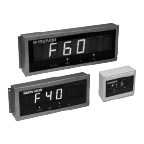
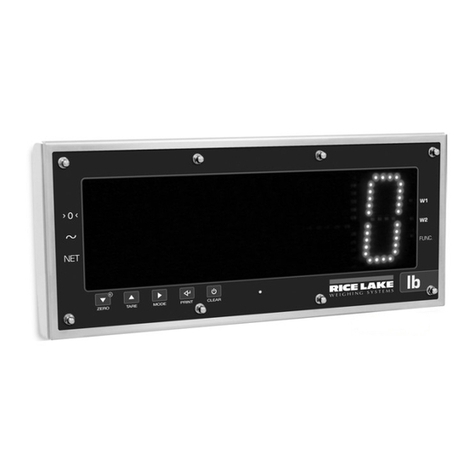
Rice Lake LaserLight Series User manual

LaserLight® Series
Remote Displays
Version 2.05
Installation Manual
6'' Remote Display
4'' Remote Display
(Available in Stainless Steel) M-Series Messaging Remote Display
8-character (Shown) or 12-character
4'' Stop/Go Remote Display
PN 75936 Rev COctober 2, 2019

An ISO 9001 registered company
© Rice Lake Weighing Systems. All rights reserved.
Rice Lake Weighing Systems® is a registered trademark of
Rice Lake Weighing Systems.
All other brand or product names within this publication are trademarks or
registered trademarks of their respective companies.
All information contained within this publication is, to the best of our knowledge, complete and
accurate at the time of publication. Rice Lake Weighing Systems reserves the right to make
changes to the technology, features, specifications and design of the equipment without notice.
The most current version of this publication, software, firmware and all other product
updates can be found on our website:
www.ricelake.com

Contents
© Rice Lake Weighing Systems ● All Rights Reserved i
Contents
Technical training seminars are available through Rice Lake Weighing Systems.
Course descriptions and dates can be viewed at www.ricelake.com/training
or obtained by calling 715-234-9171 and asking for the training department.
1.0 Introduction . . . . . . . . . . . . . . . . . . . . . . . . . . . . . . . . . . . . . . . . . . . . . . . . . . . . . . . . . . . . . . . . . . . . . . . . . . . . 1
1.1 Safety Signal Definitions: . . . . . . . . . . . . . . . . . . . . . . . . . . . . . . . . . . . . . . . . . . . . . . . . . . . . . . . . . . . . . . . . . . . . . . . . . . . . . . 1
1.2 Overview . . . . . . . . . . . . . . . . . . . . . . . . . . . . . . . . . . . . . . . . . . . . . . . . . . . . . . . . . . . . . . . . . . . . . . . . . . . . . . . . . . . . . . . . . . . 2
1.2.1 Standard Features . . . . . . . . . . . . . . . . . . . . . . . . . . . . . . . . . . . . . . . . . . . . . . . . . . . . . . . . . . . . . . . . . . . . . . . . . . . . 2
1.3 Annunciators . . . . . . . . . . . . . . . . . . . . . . . . . . . . . . . . . . . . . . . . . . . . . . . . . . . . . . . . . . . . . . . . . . . . . . . . . . . . . . . . . . . . . . . . 3
2.0 Installation/Setup. . . . . . . . . . . . . . . . . . . . . . . . . . . . . . . . . . . . . . . . . . . . . . . . . . . . . . . . . . . . . . . . . . . . . . . . 4
2.1 Unpacking and Assembly . . . . . . . . . . . . . . . . . . . . . . . . . . . . . . . . . . . . . . . . . . . . . . . . . . . . . . . . . . . . . . . . . . . . . . . . . . . . . . 4
2.2 Enclosure Disassembly. . . . . . . . . . . . . . . . . . . . . . . . . . . . . . . . . . . . . . . . . . . . . . . . . . . . . . . . . . . . . . . . . . . . . . . . . . . . . . . . 5
2.3 Wall Mounting . . . . . . . . . . . . . . . . . . . . . . . . . . . . . . . . . . . . . . . . . . . . . . . . . . . . . . . . . . . . . . . . . . . . . . . . . . . . . . . . . . . . . . . 5
2.4 Wiring . . . . . . . . . . . . . . . . . . . . . . . . . . . . . . . . . . . . . . . . . . . . . . . . . . . . . . . . . . . . . . . . . . . . . . . . . . . . . . . . . . . . . . . . . . . . . 6
2.4.1 AC Wiring . . . . . . . . . . . . . . . . . . . . . . . . . . . . . . . . . . . . . . . . . . . . . . . . . . . . . . . . . . . . . . . . . . . . . . . . . . . . . . . . . . . 6
2.4.2 Serial Wiring. . . . . . . . . . . . . . . . . . . . . . . . . . . . . . . . . . . . . . . . . . . . . . . . . . . . . . . . . . . . . . . . . . . . . . . . . . . . . . . . . 7
2.4.3 20 mA Current Loop. . . . . . . . . . . . . . . . . . . . . . . . . . . . . . . . . . . . . . . . . . . . . . . . . . . . . . . . . . . . . . . . . . . . . . . . . . . 9
2.4.4 RS-232 . . . . . . . . . . . . . . . . . . . . . . . . . . . . . . . . . . . . . . . . . . . . . . . . . . . . . . . . . . . . . . . . . . . . . . . . . . . . . . . . . . . . . 9
2.4.5 RS-485 . . . . . . . . . . . . . . . . . . . . . . . . . . . . . . . . . . . . . . . . . . . . . . . . . . . . . . . . . . . . . . . . . . . . . . . . . . . . . . . . . . . . . 9
2.4.6 Reset Switch . . . . . . . . . . . . . . . . . . . . . . . . . . . . . . . . . . . . . . . . . . . . . . . . . . . . . . . . . . . . . . . . . . . . . . . . . . . . . . . 10
2.4.7 Communicating with Indicators and LEDs . . . . . . . . . . . . . . . . . . . . . . . . . . . . . . . . . . . . . . . . . . . . . . . . . . . . . . . . . 10
2.4.8 Decimal Point (7-Segment Display) . . . . . . . . . . . . . . . . . . . . . . . . . . . . . . . . . . . . . . . . . . . . . . . . . . . . . . . . . . . . . . 10
3.0 Configuration . . . . . . . . . . . . . . . . . . . . . . . . . . . . . . . . . . . . . . . . . . . . . . . . . . . . . . . . . . . . . . . . . . . . . . . . . 11
3.1 Auto-Learn . . . . . . . . . . . . . . . . . . . . . . . . . . . . . . . . . . . . . . . . . . . . . . . . . . . . . . . . . . . . . . . . . . . . . . . . . . . . . . . . . . . . . . . . 11
3.2 Manual Configuration . . . . . . . . . . . . . . . . . . . . . . . . . . . . . . . . . . . . . . . . . . . . . . . . . . . . . . . . . . . . . . . . . . . . . . . . . . . . . . . . 11
3.3 Serial Communications . . . . . . . . . . . . . . . . . . . . . . . . . . . . . . . . . . . . . . . . . . . . . . . . . . . . . . . . . . . . . . . . . . . . . . . . . . . . . . . 15
3.4 Testing the Remote Display . . . . . . . . . . . . . . . . . . . . . . . . . . . . . . . . . . . . . . . . . . . . . . . . . . . . . . . . . . . . . . . . . . . . . . . . . . . 18
3.4.1 Display . . . . . . . . . . . . . . . . . . . . . . . . . . . . . . . . . . . . . . . . . . . . . . . . . . . . . . . . . . . . . . . . . . . . . . . . . . . . . . . . . . . . 18
3.4.2 Digital Outputs . . . . . . . . . . . . . . . . . . . . . . . . . . . . . . . . . . . . . . . . . . . . . . . . . . . . . . . . . . . . . . . . . . . . . . . . . . . . . . 19
3.4.3 Digital Inputs . . . . . . . . . . . . . . . . . . . . . . . . . . . . . . . . . . . . . . . . . . . . . . . . . . . . . . . . . . . . . . . . . . . . . . . . . . . . . . . 19
3.4.4 Loop Back . . . . . . . . . . . . . . . . . . . . . . . . . . . . . . . . . . . . . . . . . . . . . . . . . . . . . . . . . . . . . . . . . . . . . . . . . . . . . . . . . 19
3.5 Version . . . . . . . . . . . . . . . . . . . . . . . . . . . . . . . . . . . . . . . . . . . . . . . . . . . . . . . . . . . . . . . . . . . . . . . . . . . . . . . . . . . . . . . . . . . 19
3.6 Demand Print Displaying. . . . . . . . . . . . . . . . . . . . . . . . . . . . . . . . . . . . . . . . . . . . . . . . . . . . . . . . . . . . . . . . . . . . . . . . . . . . . . 20
3.7 Serial Commands . . . . . . . . . . . . . . . . . . . . . . . . . . . . . . . . . . . . . . . . . . . . . . . . . . . . . . . . . . . . . . . . . . . . . . . . . . . . . . . . . . . 20
3.7.1 Command Format (7-Segment) . . . . . . . . . . . . . . . . . . . . . . . . . . . . . . . . . . . . . . . . . . . . . . . . . . . . . . . . . . . . . . . . . 21
3.7.2 Set or Get the Digital I/O (7-Segment with Stop/Go Light). . . . . . . . . . . . . . . . . . . . . . . . . . . . . . . . . . . . . . . . . . . . . 22
3.7.3 Display Message Command Format (Matrix Display) . . . . . . . . . . . . . . . . . . . . . . . . . . . . . . . . . . . . . . . . . . . . . . . . 23
4.0 Options . . . . . . . . . . . . . . . . . . . . . . . . . . . . . . . . . . . . . . . . . . . . . . . . . . . . . . . . . . . . . . . . . . . . . . . . . . . . . . . 24
4.1 Time and Date. . . . . . . . . . . . . . . . . . . . . . . . . . . . . . . . . . . . . . . . . . . . . . . . . . . . . . . . . . . . . . . . . . . . . . . . . . . . . . . . . . . . . . 24
4.1.1 Setting the Time and Date . . . . . . . . . . . . . . . . . . . . . . . . . . . . . . . . . . . . . . . . . . . . . . . . . . . . . . . . . . . . . . . . . . . . . 24
4.2 Temperature . . . . . . . . . . . . . . . . . . . . . . . . . . . . . . . . . . . . . . . . . . . . . . . . . . . . . . . . . . . . . . . . . . . . . . . . . . . . . . . . . . . . . . . 25
4.3 Visor Installation . . . . . . . . . . . . . . . . . . . . . . . . . . . . . . . . . . . . . . . . . . . . . . . . . . . . . . . . . . . . . . . . . . . . . . . . . . . . . . . . . . . . 25
4.4 Pole Mount Kit. . . . . . . . . . . . . . . . . . . . . . . . . . . . . . . . . . . . . . . . . . . . . . . . . . . . . . . . . . . . . . . . . . . . . . . . . . . . . . . . . . . . . . 25
4.5 Traffic Light Option . . . . . . . . . . . . . . . . . . . . . . . . . . . . . . . . . . . . . . . . . . . . . . . . . . . . . . . . . . . . . . . . . . . . . . . . . . . . . . . . . . 27
4.5.1 Dry Contact Wiring . . . . . . . . . . . . . . . . . . . . . . . . . . . . . . . . . . . . . . . . . . . . . . . . . . . . . . . . . . . . . . . . . . . . . . . . . . . 28
4.5.2 Single Switch Wiring . . . . . . . . . . . . . . . . . . . . . . . . . . . . . . . . . . . . . . . . . . . . . . . . . . . . . . . . . . . . . . . . . . . . . . . . . 28
4.5.3 Two Switch Wiring . . . . . . . . . . . . . . . . . . . . . . . . . . . . . . . . . . . . . . . . . . . . . . . . . . . . . . . . . . . . . . . . . . . . . . . . . . . 28
5.0 Appendix . . . . . . . . . . . . . . . . . . . . . . . . . . . . . . . . . . . . . . . . . . . . . . . . . . . . . . . . . . . . . . . . . . . . . . . . . . . . . 29
5.1 Error Messages. . . . . . . . . . . . . . . . . . . . . . . . . . . . . . . . . . . . . . . . . . . . . . . . . . . . . . . . . . . . . . . . . . . . . . . . . . . . . . . . . . . . . 29
5.2 Replacement Parts . . . . . . . . . . . . . . . . . . . . . . . . . . . . . . . . . . . . . . . . . . . . . . . . . . . . . . . . . . . . . . . . . . . . . . . . . . . . . . . . . . 29

LaserLight Series
ii Visit our website www.RiceLake.com
Rice Lake continually offers web-based video training on a growing selection
of product-related topics at no cost. Visit www.ricelake.com/webinars
5.2.1 UL Approved Replacement Parts. . . . . . . . . . . . . . . . . . . . . . . . . . . . . . . . . . . . . . . . . . . . . . . . . . . . . . . . . . . . . . . . 29

5.2.2 7-Segment Display Replacement Parts . . . . . . . . . . . . . . . . . . . . . . . . . . . . . . . . . . . . . . . . . . . . . . . . . . . . . . . . . . . 30
5.2.3 8 and 12-Character Display Replacement Parts . . . . . . . . . . . . . . . . . . . . . . . . . . . . . . . . . . . . . . . . . . . . . . . . . . . . 33
5.3 LaserLight Remote Display Enclosure Dimensions . . . . . . . . . . . . . . . . . . . . . . . . . . . . . . . . . . . . . . . . . . . . . . . . . . . . . . . . . 37
5.4 LaserLight Matrix Display Enclosure Dimensions . . . . . . . . . . . . . . . . . . . . . . . . . . . . . . . . . . . . . . . . . . . . . . . . . . . . . . . . . . . 38
6.0 Specifications . . . . . . . . . . . . . . . . . . . . . . . . . . . . . . . . . . . . . . . . . . . . . . . . . . . . . . . . . . . . . . . . . . . . . . . . . 39

Introduction
© Rice Lake Weighing Systems ● All Rights Reserved 1
1.0 Introduction
This manual is intended for use by service technicians responsible for installing and servicing the LaserLight ® LED remote display.
Installation procedures are written in the order to be followed by the installer: pre-installation setup, configuration and on-site installation.
Manuals and additional resources are available from the Rice Lake Weighing Systems website at www.ricelake.com
Warranty information can be found on the website at www.ricelake.com/warranties
1.1 Safety Signal Definitions:
Indicates an imminently hazardous situation that, if not avoided, will result in death or serious injury. Includes
hazards that are exposed when guards are removed.
Indicates a potentially hazardous situation that, if not avoided, could result in serious injury or death. Includes
hazards that are exposed when guards are removed.
Indicates a potentially hazardous situation that, if not avoided, could result in minor or moderate injury.
Indicates information about procedures that, if not observed, could result in damage to equipment or corruption
to and loss of data.
General Safety
Do not operate or work on this equipment unless this manual has been read and all instructions are understood.
Failure to follow the instructions or heed the warnings could result in injury or death. Contact any Rice Lake
Weighing Systems dealer for replacement manuals.
Failure to heed could result in serious injury or death.
Some procedures described in this manual require work inside the indicator enclosure. These procedures are to be performed by
qualified service personnel only.
Do not allow minors (children) or inexperienced persons to operate this unit.
Do not operate without all shields and guards in place.
Do not place fingers into slots or possible pinch points.
Do not use any load-bearing component that is worn beyond 5% of the original dimension.
Do not use this product if any of the components are cracked.
Do not exceed the rated load limit of the unit.
Do not make alterations or modifications to the unit.
Do not remove or obscure warning labels.
Before opening the unit, ensure the power cord is disconnected from the outlet.
DANGER
WARNING
CAUTION
IMPORTANT
WARNING

LaserLight Series
2 Visit our website www.RiceLake.com
1.2 Overview
The LaserLight remote display features a super-bright LED display and non-glare filtered lens for use in a wide variety of
applications. The LaserLight Series are available with a 7-segment, 6-digit display or an eight or 12-character matrix display.
The LaserLight remote display is designed to work with most digital weight indicators, host computers, and peripherals using a
20 mA current loop, RS-232 or RS-485 communications.
The unique IntelliBright™ feature uses a photo sensor to read ambient light and automatically adjusts the LaserLight display
between day and night settings.
The display has seven internal buttons and three external buttons to set various parameters. The external buttons include two
for setting the time and date, and one for the learn sequence. The configuration menu is entered via the setup button and is
displayed on the display board panel for easy configuration of the unit.
This manual provides installation and configuration instructions for the display.
1.2.1 Standard Features
The LaserLight 7-segment remote display is available in 4" or 6" digit sizes and the matrix display is available in 2.5" character
size with 8 or 12 positions. The LaserLight 4-SG remote display comes in a 4" digit size in a 6" enclosure size. Both styles use
an Auto-Learn function which automatically determines the serial settings and data format used by the attached indicator.
Additional standard features include:
• Hold displayed weight (demand input)
• Adjustable daylight/night intensity
• Mirror function (weight only)
• Auto-sensing 115/230 VAC power supply
• Mode and unit legends
• Echo
• Traffic light option (4" digit size only)
• Time and date (4", 4"-SG, 6" only)
Optional Features
Optional features of the LaserLight remote display include:
• Temperature
• Field-installable metal visor for all models
• UL Approved Unit
• Time and date (M-Series, 8 and 12 character)

Introduction
© Rice Lake Weighing Systems ● All Rights Reserved 3
UL 48 Approved Safety
Figure 1-1. Safety Labels – UL Approved Models
UL 48 Approval For
• Wet location
• Cord connected
• Stationary sign
Test operation of ground fault circuit interrupter each time the LaserLight is plugged in.
All labels must be in legible condition. If illegible, replace using the part numbers found within Figure 1-1.
1.3 Annunciators
The 7-segment LaserLight remote display uses a set of four high-intensity LED annunciators (Figure 1-2). The matrix display
uses two positions of the display to display arrows which provide additional information about the value being displayed
(Figure 1-3):
Gross and Net annunciators are lit to indicate whether the displayed weight is a gross or net weight.
•lb, kg annunciators indicate the units associated with the displayed value and represent primary and secondary units
• Red, green circle and green arrow annunciators indicate the traffic light state on the display; Feature applies to only the
LaserLight 4-SG
Figure 1-2. 7-Segment Front Panel Display
Figure 1-3. Matrix Display Front Panel
PN 154025
PN 154027
PN 154026
PN 154028
IMPORTANT
LED Annunciators
Optional Traffic
Light Display
Arrow
Annunciators

LaserLight Series
4 Visit our website www.RiceLake.com
2.0 Installation/Setup
The LaserLight remote display can be set up and configured once it is mounted. This section describes basic installation,
AC wiring, RS-232, RS-485 and 20 mA current loop connections. Once installation setup is complete, see Section 3.0 on
page 11 for information on configuring the remote display.
The LaserLight has no on/off switch. Before opening the unit, ensure the power cord is disconnected from the
power outlet.
Use a wrist strap to ground yourself and protect components from electrostatic discharge (ESD) when working
inside the enclosure.
This unit uses double pole/neutral fusing which could create an electric shock hazard. Procedures requiring
work inside the remote display must be performed by qualified service personnel only.
2.1 Unpacking and Assembly
Immediately after unpacking, visually inspect the LaserLight remote display for damage. If parts were damaged in shipment,
notify Rice Lake Weighing Systems and the shipper immediately. The main components of the LaserLight remote display
include:
• Powder coated steel or stainless steel enclosure
• Primary and secondary display boards
• Power supply
• Mounting panel for the CPU board (located on back of mounting plate)
Remove the protective plastic on the lens of the LaserLight as it obscures the display over time and becomes
very difficult to remove later on.
Figure 2-1. Mounting Plate Indicating Primary / Secondary Display Boards (7-Segment Display)
WARNING
CAUTION
IMPORTANT
Primary Display Secondary Display

Installation/Setup
© Rice Lake Weighing Systems ● All Rights Reserved 5
2.2 Enclosure Disassembly
For ease of installation, remove the mounting plate (which includes the primary and secondary display boards) before installing
the LaserLight remote display. This protects the LEDs from unnecessary jarring and makes the enclosure lighter for installation.
Use the following steps to remove the mounting plate from the enclosure.
Use caution when lowering/raising the mounting plate to ensure LEDs do not contact the enclosure sides.
1. Remove the captive screws located on the bottom of the enclosure. The mounting plate is located on the inside of the
enclosure, on a frame which can be held in place by tabs and two pins (Figure 2-2).
2. Glide the mounting plate frame downward, allowing it to hang freely beneath the enclosure.
3. Disconnect the chassis ground wire from the top of the mounting plate mounting frame.
4. Disconnect the AC cord assembly from the power supply.
5. Using a slight diagonal twisting motion, slide the mounting plate out from the inside of the enclosure and set it aside.
Figure 2-2. Tab Pin Assembly on Inside of Remote Display Enclosure
2.3 Wall Mounting
The LaserLight remote display can be mounted to vertical surfaces or a pole.
Select a site and use installation screws or wall anchors to secure the remote display to a wall using the mounting holes on the
flange tabs. The flange hole size accommodates 1/4" hardware.
Figure 2-3. Mounting Flange 4'' LED Remote Display
An optional pole mounting kit, which fits 4" - 8" poles, must be used when installing a remote display on a pole (Section 4.4 on
page 25).
Once the enclosure is secured, slide the mounting plate down to allow it to hang freely from the enclosure with the tabs secured
against the pins. This enables the user to continue wiring the remote display.
IMPORTANT
Flange tab with holes to
accommodate 1/4"
hardware for mounting

LaserLight Series
6 Visit our website www.RiceLake.com
2.4 Wiring
The LaserLight remote display provides three cord grips located on the underside of the enclosure for cabling, one for the
power cord (supplied) and two for serial communications. The LaserLight remote display is pre-wired. Only the serial
communications cable must be connected. An A/C power cord is also supplied.
Use the following steps to wire the remote display:
The LaserLight remote display has no on/off switch. Before opening the unit, ensure the power cord is
disconnected from the power outlet.
1. Open the display and lower the mounting plate (Section 2.2 on page 5).
Use caution when lowering or raising the mounting plate to ensure the LEDs do not contact the enclosure sides.
2. Loosen the retaining screws located on the front of mounting plate (Figure 2-4). The mounting plate is hinged on a
backplate frame to allow easier access to the AC wiring and the CPU board.
Figure 2-4. Retaining Screw Location
2.4.1 AC Wiring
The LaserLight power supply can run on either 115 or 230 VAC.
The AC wiring is run through the cord grip to a 3-position AC terminal block bracket on the inside of the enclosure. This bracket
can be removed by loosening the two standoffs and lifting it off. It can be lowered and pulled outside of the enclosure to ease
wiring connections.
Figure 2-5. Inside Enclosure Backplate Diagram
Refer to the following table for AC wiring connections.
Ensure a ground wire is attached to the grounding stud located on the enclosure backplate.
3-Pin Terminal Block on Enclosure Back To Power Supply To Power Supply
Pin Wire Color Pin UL Approved Unit
1 Neutral Blue or White 1 N
2 Hot Brown or Black 2 L
3 Ground Green or Green/Yellow Ground Tab
Table 2-1. AC Wiring Connections
WARNING
IMPORTANT
Retaining Screw
Grounding Stud
AC Terminal Block
IMPORTANT

Installation/Setup
© Rice Lake Weighing Systems ● All Rights Reserved 7
2.4.2 Serial Wiring
Serial communications are connected to the CPU board using removable screw terminal plugs on J6, J8 and J9
(Figure 2-9 on page 9).
To connect the communications cable to the remote display:
The LaserLight remote display has no on/off switch. Before opening the unit, ensure the power cord is
disconnected from the power outlet.
1. Open the display and lower the mounting plate (Section 2.2 on page 5).
2. Remove the captive retaining screws and flip forward the hinged mounting plate.
Figure 2-6. LED Primary and Secondary Display Boards (7-Segment Display)
3. Loosen the serial cable cord grip and push enough communications cable into the enclosure to allow attachment to
the CPU board.
4. Strip serial cable jacket back to cord grip (metal construction) location to expose the braided shield. Trim the braid,
shield wire or foil back to within 1" (1.5 cm) of stripped cable jacket (Figure 2-7).
5. Feed the cable through the dome nut and clamping insert. Fold the braided shield over the clamping insert, making
sure the braided shield overlaps the O-ring by 3/32" (0.2 cm).
6. Push the clamping insert into the body and tighten the dome nut.
7. Make cable connections for RS-232, RS-485, or 20 mA current loop communications.
8. Tighten the serial cable cord grip.
Figure 2-7. Serial Cord Grip Assembly
WARNING
Captive Retaining Screw
Step 4 Step 5 Step 6

LaserLight Series
8 Visit our website www.RiceLake.com
RF Interference
If experiencing RF Interference, follow the instructions below.
1. Loop the serial wires through the cylindrical ferrite (PN 66730) provided with this manual.
2. Using the plastic cable ties provided, secure the wires to the ferrite and the serial cable to the learn switch wires to
keep ferrite from contacting the CPU board.
Figure 2-8. Cylindrical Ferrite Placement
Terminals J6, J8, and J9 are removable screw terminal plugs.
Port 0 is used for input only and port 1 is used to drive the next LaserLight Remote Display.
Connector Pin Assignment Function Port Position
J1 1 Ground –
2 Digin 0 –
3 Digin 1 –
4 +5 V –
5 DigOut 0 –
6 DigOut 1 –
7 Ground –
J6 1 20 mA Rx+ Port 0
2 20 mA Rx– Port 0
3 20 mA Tx+ Port 1
4 20 mA Tx– Port 1
J8 1 RS-232 TxD 0 Port 0
2 RS-232 TxD 1 Port 1
3 RS-232 RxD 0 Port 0
4 RS-232 RxD 1 Port 1
5 RS-232 SIG GND –
6 RS-232 SIG GND –
J9 1 RS-485 Rx+ Port 0
2 RS-485 Rx– Port 0
3 RS-485 Tx+ Port 0
4 RS-485 Tx– Port 0
Table 2-2. Serial Communications Wiring
Cylindrical Ferrite
Plastic Cable Ties
Note

Installation/Setup
© Rice Lake Weighing Systems ● All Rights Reserved 9
LaserLight Remote Display CPU Board
Port 0 which is connected to the indicator supports three configurations: 20 mA, RS-232, and RS-485 communications.
Port 1 which is the Echo port, supports 20 mA and RS-232 communications.
Figure 2-9. LaserLight Remote Display CPU Board
2.4.3 20 mA Current Loop
20 mA current loop communication is provided on connector J6 of the CPU board (Figure 2-9 and Table 2-2 on page 8).
Ensure receive jumpers are across RX0, 20 mA and select active or passive switch settings. Remove unused jumpers
(Figure 2-10).
2.4.4 RS-232
The RS-232 connection is provided on connector J8 of the CPU board (Figure 2-9 and Table 2-2 on page 8).
Ensure transmit and receive jumpers are across TX0 232 and RX0 232 (Figure 2-10).
2.4.5 RS-485
The RS-485 connection is provided on connector J9 of the CPU board (Figure 2-9 and Table 2-2 on page 8).
Ensure transmit and receive jumpers are across TX0 485 and RX0 485 (Figure 2-10).
Figure 2-10. Jumper Pin Locations (Board Revision G and Later)
J9
J8
J6
J5
J7
J4 ISP
Port 0 Jumpers/TX and RX LEDs
Reset Switch
Port 1 Jumpers/TX LEDs
20 mA Active/Passive Selector Switches

LaserLight Series
10 Visit our website www.RiceLake.com
2.4.6 Reset Switch
The reset switch enables a simulated power up reset. It goes back to normal operation mode. The reset switch eliminates
having to unplug the unit to do a reset, see Figure 2-10 on page 9 for the reset switch location on the CPU board.
2.4.7 Communicating with Indicators and LEDs
Small LEDs located on the CPU board flash when serial data is received or sent. The transmit indicators flash when data is
being sent out of the port. The receive indicator flashes when the data is received. A steady indicator on receive LEDs reflect a
connection with no streaming data, see Figure 2-10 on page 9 for communication indicator locations on the CPU board.
2.4.8 Decimal Point (7-Segment Display)
The primary display board has decimal LED’s. These can be changed to commas by moving a jumper located on the front of
the display board (Figure 3-2 on page 12).
Ensure the decimal point/comma jumper is in the proper position on the display board.

Configuration
© Rice Lake Weighing Systems ● All Rights Reserved 11
3.0 Configuration
Once the LaserLight remote display is installed, it may need to be configured if the indicator requires special settings.
Configuration can be done manually and is explained in Section 3.2.
Using Auto-Learn simplifies installation by automatically detecting the communications format and data rate used by the
indicator and eliminates the need for configuration, see Section 3.1 for an overview of Auto-Learn.
3.1 Auto-Learn
The LaserLight remote display incorporates a software feature called Auto-Learn. Auto-Learn examines the serial data stream
sent from the attached indicator and attempts to determine the data settings and format used by the indicator.
Auto-Learn occurs automatically when Port 0 is not locked via software configuration (not locked by default) and the connecting
indicator is configured to send continuous (streaming) data (Table 3-5 on page 17). It also occurs automatically if the currently
streamed format changes. LaserLight Auto-Learns by itself in most cases. This process can be forced by pressing the external
Auto-Learn button.
Use the following quick steps for Auto-Learn.
1. Open the enclosure per disassembly instructions in Section 2.2 on page 5 and connect the serial interface.
2. Visually inspect to ensure the Auto-Learn button is connected to J5 on the CPU board, see Figure 3-1 for plug-in
location.
3. Power up the remote display.
4. Momentarily press the Learn button.
5. Use the right and left buttons to shift the displayed data string if the displayed weight is not positioned with LSD.
If using an indicator with a Toledo T8142 format, follow Step 1–Step 5 then go to SP IND in the serial menu. Select 1
under special indicators.
It is recommended to lock Port 0 to eliminate un-intentional changes from occurring (Table 3-5 on page 17).
3.2 Manual Configuration
To begin configuration, open the enclosure, see Section 2.2 on page 5 for enclosure disassembly instructions, to access the
CPU board (Figure 3-1 and Figure 3-2 on page 12).
Figure 3-1. LaserLight CPU Board
Note

LaserLight Series
12 Visit our website www.RiceLake.com
The setup button is located on the secondary display board (Figure 3-2).
Figure 3-2. Setup Button Location on Secondary Display Board (7-Segment Display)
The display board is mounted on a hinged mounting plate to allow for easy access to the CPU board. Press the SETUP button
to access main menu configuration parameters.
Main menu parameters include:
• Configuration
• Serial communications
• Test
• Version
The LaserLight remote display can be configured and displayed using a series of menus accessed using internal buttons
located on the secondary display (Figure 3-3).
Figure 3-3. Configuration Setup Buttons
Use the UP/DOWN, LEFT/RIGHT buttons to navigate through menu items and the ENTER button for setting a selection.
Figure 3-4. LaserLight Main Menu Options
Jumper position for
decimal point or comma
Setup button
DOWN
RIGHT
LEFT
UP
SETUP
ENTER
TESTSERIALCONFIG VER

Configuration
© Rice Lake Weighing Systems ● All Rights Reserved 13
Table 3-1 summarizes the functions of each of the main menus and Figure 3-5 illustrates the main menu selections.
When configuring the indicator attached to the remote display, ensure the decimal point configuration is compatible with the
remote display. The LaserLight 7-segment remote display allows none, one or two decimal places, see Figure 3-2 on page 12
for jumper positions. The 8- or 12-character matrix displays use of one character position for the decimal point.
Figure 3-5. Configuration Main Menu Choices
With the 8 and 12-character matrix displays some of the labels are not shortened, for example STDSTL in the
7-segment is STAND STILL on the 12-character display.
7-Segment
Display Menu
8-Character Matrix
Display Menu
12-Character Matrix
Display Menu Menu Function
CONFIG CONFIG CONFIG Configuration; Configures time and date (option), temperature
(option), display brightness, mirroring, and other parameters
associated with configuring the remote display
SERIAL SERIAL SERIAL Serial; Configures serial ports
TEST TEST TEST Test; System hardware tests
VER VERSION VERSION Version; Displays installed software version number
Table 3-1. LaserLight Remote Display Menu Summary
TIM DAT TEMP BRIGHT
ENABLE
Off
On
ISO
USA
Minutes
Hour
FORMAT SET DATE
Month
Day
Year
SUPP 0 MIRROR STDSTL ADDRES MSG TM D TEST RESET
On
Off
C
FDAY
On
Off
Off
On
Off
On 0 - 31
Off
On
CONFIG SERIAL TEST VER
15 sec
5 sec
30 sec
1 min
5 min
Reset
1
2
3
4
5
6
7
8
9
10
LEARN EN
Off
On NIGHT
TEMP ADJ
+/- 5
1
2
3
4
5
6
7
8
9
10
Note

LaserLight Series
14 Visit our website www.RiceLake.com
CONFIG Menu
7-Segment
Display Parameter
8-Character
Matrix Display
12-Character
Matrix Display Choices Description
Level 2 Submenus
TIMDAT TIMEDATE TIME/DATE Enabled To enable time and date
Format Displays USA or ISO time format
Set Sets hours/minutes and month/day/year
Date Can disable date
TEMP TEMP TEMPERATURE FSelect Fahrenheit
C Select Celsius
TEMPADJ TEMPADJ DEGREE
ADJUST
+5% ±5° display; Can add or subtract up to ±5° of both Fahrenheit or
Celsius
-5%
BRIGHT BRIGHT BRIGHTNESS Day Selects the brightness during day or nighttime hours
Night
SUPP O SUPP O SUPPRESS 0 On Select On to enable the suppression of leading zeros in a weight
Off
MIRROR MIRROR MIRROR On Select On to display LED readout in reverse; The menu is viewed
normally
Off
STDSTL STD STL STAND STILL On Select On to enable display updated weight only when the scale
is not in motion
Off
ADDRES ADDRESS ADDRESS 0–31 Assign a command address by selecting a number between 0–31
MSG TM MSG TIME MESSAGE TIME 5 seconds Select amount of time a message stays on the remote display;
Time can vary from 5 seconds to 5 minutes; If no serial command
is used then this parameter is not used (7-segment DM
command only)
15 seconds
30 seconds
1 minute
5 minutes
D TEST DSP TEST DISPLAY TEST On Set this parameter On to enable a countdown display test on
start up
Off
RESET RESET RESET CONFIG -- Resets the remote display to default parameters
LEARN EN LEARN EN LEARN EN On Enable allows weight learn operation; With Learn off, the unit
operates for demand messages
Off
Table 3-2. Configuration Menu Summary - Level 2
Parameter Choices Description
Level 3 Submenus (TIMDAT Parameter)
ENABLE On An additional chip called a “snap hat” is required; Select On to enable time and date option; It is recommended to disable
the time/date feature if this additional chip is not wanted; The unit displays at zero or less weight only
Off
FORMAT USA Displays USA format
ISO Displays ISO (military time) format
SET HH/MM Sets hour/minutes
MM/DD/YYYY Sets month/day/year
DATE On Select Off to disable the date display if the date and time option is installed; Time is still displayed
Off
Brightness (BRIGHT Parameter)
DAY 1–10 Selects the brightness during day; Brightness is set from 1–10 or 10–100% of the full brightness; IntelliBright averages
measured ambient light over a ten minute time span
NIGHT 1–5–10 Selects the brightness during night; Brightness is set from 1–10 or 10–100% of the full brightness; IntelliBright averages
measured ambient light over a ten minute time span
Table 3-3. Configuration Menu Summary - Level 3

Configuration
© Rice Lake Weighing Systems ● All Rights Reserved 15
3.3 Serial Communications
The LaserLight remote display has two serial ports available:
• Port 0 - provides communication with the indicator
• Port 1 - provides echoing OF INDICATOR DATA
There are 15 sub-parameters associated with Port 0 and six sub-parameters associated with Port 1 (Figure 3-6).
See Section 2.4.2 on page 7 for serial wiring positions.
Figure 3-6. Serial Menu
PORT0 PORT1
BAUD PARITY DATA
BAUD PARITY DATA
Even
Odd
8
7
None
Even
Odd
None
CONFIG SERIAL TEST VER
HOLD WT LOCK E CHAR LWPOS
Off
On
Off
On
LR
CR
FF
ETX
number
between
5-50
STOP
8
7
2
1
LENGTH
number
between 5-75
GROSSC NETC MOTION
A - Z
SP IND
0
1200
2400
4800
9600
19200
1200
2400
4800
9600
19200
ECHO LOCK
Off
On
On
Off
STOP
2
1
PRIMU SECU
number
between
5-75 1
2
3
4
5
A - Z A - Z A - Z A - Z

LaserLight Series
16 Visit our website www.RiceLake.com
Serial Menu
Parameter Choices Description
Level 2 Submenus
Port 0 BAUD Configure Port 0; See Level 3 submenu parameter descriptions
PARITY
DATA BITS
STOP BITS
HOLD WT Keeps last weight displayed if communication is lost and prevents the remote display from going into an error condition
LOCK If enabled, prevents the Auto-Learn parameter from working and ensures settings remain currently set
(Section 3.1 on page 11)
E CHAR This feature looks at the last character to determine the end of a packet
LW POS Can select a number between 5 and 50; Is zero indexed and determines last weight position of the format
LENGTH Can select a number between 5 and 75 and determines the length of packet in the string format
PRIM U Select primary unit characters
SEC U Select secondary unit characters
GROS C Select gross character
NET C Select net character
MOTION Select motion status character
SP IND Select, decode status, and settings for special indicator type
0 = none
1 = Toledo 8142 format
PORT 1 BAUD Configure Port 1, see level 3 submenu parameter descriptions
PARITY
DATA BITS
STOP BITS
ECHO Disable this to allow echoing between remote display and other devices; Data settings must be set equal to or greater
than device being echoed to
LOCK If disabled, remote display uses same settings as indicator after an Auto-Learn
Table 3-4. Serial Communication Menu Summary
Table of contents
Other Rice Lake Monitor manuals

Rice Lake
Rice Lake 1280 Enterprise Series Installation manual

Rice Lake
Rice Lake LaserLight2 ConnexLink 167091 User manual

Rice Lake
Rice Lake MSI-8000 User manual

Rice Lake
Rice Lake LaserLight3 User manual

Rice Lake
Rice Lake LaserLight User manual

Rice Lake
Rice Lake SURVIVOR IQ L Series User manual

Rice Lake
Rice Lake CLS-680 User manual

Rice Lake
Rice Lake SURVIVOR IQ F Series User manual

Rice Lake
Rice Lake RD-300 User manual

Rice Lake
Rice Lake LaserLT-60 User manual