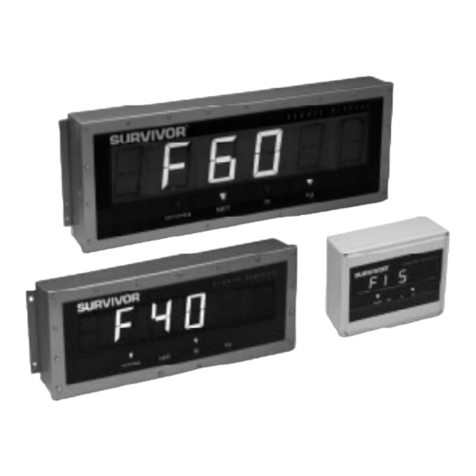
Rice Lake SURVIVOR IQ L Series User manual

43546
SURVIVOR
®
IQ
L-Series
LCD Remote Displays
Models L20 and L30
Installation Manual

Copyright © 1998 Rice Lake Weighing Systems. All rights reserved. Printed in the United States of America.
Specifications subject to change without notice.
Version 1.1, August 1998
Contents
About This Manual................................................................................................................................... 1
1.0 Introduction.................................................................................................................................. 1
2.0 Pre-Installation Setup.................................................................................................................. 2
2.1 Indicator Connections......................................................................................................................... 2
2.1.1 RS-232...................................................................................................................................................... 2
2.1.2 20 mA Current Loop.................................................................................................................................. 2
3.0 Configuration................................................................................................................................ 4
3.1 DIP Switch Configuration.................................................................................................................... 4
3.1.1 Serial Communications .............................................................................................................................. 4
3.1.2 Primary and Secondary Units..................................................................................................................... 5
3.1.3 Display Type .............................................................................................................................................. 5
3.1.4 Learn Mode (AutoLink)............................................................................................................................... 5
3.1.5 Display Characteristics............................................................................................................................... 6
3.1.6 Time and Temperature Options.................................................................................................................. 6
3.1.7 Suppress Leading Zeroes.......................................................................................................................... 7
3.1.8 Loop-Back Self-Test.................................................................................................................................. 7
3.1.9 CPU Board Part Number ........................................................................................................................... 7
3.1.10 Indicator Type/Serial Format ..................................................................................................................... 7
3.2 Setting the Clock (for Units with the Time Option Installed).................................................................. 7
4.0 On-Site Installation...................................................................................................................... 9
4.1 Sealing the Enclosure ......................................................................................................................... 9
4.2 Mounting the Enclosure...................................................................................................................... 9
4.3 Connecting Cables............................................................................................................................. 9
4.4 Remote Display Self-Test.................................................................................................................... 9
5.0 Troubleshooting and Repair....................................................................................................... 11
5.1 Error Messages ................................................................................................................................ 11
5.2 Board Diagrams ............................................................................................................................... 12
5.2.1 CPU Board .............................................................................................................................................. 12
5.2.2 Power Supply Board................................................................................................................................ 12
5.2.3 LCD Display Boards................................................................................................................................. 13
5.3 Backlighting Components................................................................................................................. 13
5.4 Loop-Back Self-Test......................................................................................................................... 16
5.5 Replacement Parts........................................................................................................................... 16
6.0 Specifications............................................................................................................................ 17
L-Series Remote Displays Limited Warranty......................................................................................... 18

ii
L Series Remote Displays Installation Manual

Introduction
1
About This Manual
This manual is intended for use by service technicians
responsible for installing and servicing the L-Series
LCD remote displays. Installation procedures are
presented in the order likely to be followed by the
installer: pre-installation setup, configuration, on-site
installation.
This manual applies to units using Version 1.1 of the
L-Series remote display software.
Most procedures described in this
manual require work inside the remote
display enclosure. These procedures are
to be performed by qualified service
personnel only.
Authorized distributors and their employees
can view or download this manual from the
Rice Lake Weighing Systems distributor
site at
www.rlws.com
.
1.0 Introduction
The L-Series LCD remote displays provide
high-visibility, six-digit display capability for use in a
wide variety of applications. This manual provides
installation and configuration instructions for the L20
(2-inch) and L30 (3-inch) LCD remote displays.
The L-Series remote displays are designed to work
with most digital weight indicators using 20 mA
current loop or RS-232 communications. The
AutoLink
™
learn mode function allows the L-Series
displays to automatically determine the data rate and
format sent by the attached indicator.
Fluorescent backlighting for improved visibility is
standard on all L-Series models. Optional features
include time and temperature display.
Optional Features
Table 1-1 lists the optional features available for the
L-Series remote displays. Units can be ordered from
the factory with these options already installed, or the
options can be separately ordered and installed into
existing L-Series displays.
Warning
Option Model PN
Time All 43522
Temperature All 43412
Table 1-1. Options for L-Series Remote Displays

2
L-Series Remote Displays Installation Manual
2.0 Pre-Installation Setup
The L-Series remote displays should be set up,
configured, and tested before delivery to the
installation site.
This section describes RS-232 and 20 mA current
loop indicator connections. Once pre-installation
setup is complete, go to Section 3.0 for information
about configuring the remote display.
Use a wrist strap to ground yourself and
protect components from electrostatic
discharge (ESD) when handling chips
and working inside the remote display
enclosure.
2.1 Indicator Connections
To connect the communications cable to the remote
display, do the following:
1. Disconnect power and open the remote
display enclosure.
2. For Model L30, turn the retaining screws and
lower the hinged LCD display mounting
panel. For the Model L20, remove the two
nuts from the hinged LCD display mounting
panel, then lower the panel.
3. Loosen the serial cable cord grip and push
only enough communications cable into the
enclosure to allow attachment at the terminal
block.
4. Strip 1/4 inch (.65 cm) of insulation from the
serial cable ends.
5. Make cable connections for RS-232 or 20 mA
current loop communications as described in
Sections 2.1.1 or 2.1.2, below.
6. For RS-232 connections, remove jumper
JMP1 on the CPU board (see Figure 2-1).
7. Remove any excess cable from inside the
enclosure, then tighten the serial cable cord
grip.
The DIP switches on the remote display CPU board
should be set and the remote display configuration
verified before sealing the display enclosure. DIP
switch configuration is described in Section 3.0.
A loop-back self-test can be used to test the function
of the remote display serial port. See Section 5.4 on
page 16 for information about the loop-back self-test.
2.1.1 RS-232
Figure 2-2 on page 3 shows the connections required
for RS-232 communications to the remote display.
See the manual for your indicator to determine the
indicator pin assignments for RS-232
communications.
2.1.2 20 mA Current Loop
Figures 2-3 and 2-4 show the connections required for
passive or active 20 mA current loop communications
to the remote display. See the manual for your
indicator to determine the indicator pin assignments
for 20 mA communications.
Figure 2-1. Locations of Jumper JMP1 and 20 mA Chips on
Right Edge of CPU Board
Caution
J1
POWER INPUT
+15
+5
GND
GND
J3
JMP1
20mA/RxD
U9
U14
20 mA TxD
20 mA RxD
15V pull-up
5V pull-up
+
+ +
RS-232
42004100
Jumper JMP1:
Remove for RS-232,
leave on for 20 mA
20 mA chips:
4200 chip in socket U9
4100 chip in socket U14
Pre-Installation Setup
3
Figure 2-2. RS-232 Indicator Connections to Remote
Display Terminal Block Figure 2-3. 20 mA Current Loop Connections: Passive
Remote Display, Active Indicator
Figure 2-4. 20 mA Current Loop Connections: Active
Remote Display, Passive Indicator
TxD
RxD
GND
Indicator
Serial Port
Remote Display
Terminal Block
RxD CL+
RxD CL–
GND
TxD CL+
TxD CL–
TxD
RTS
RxD
CTS
GND
I1+
I2+
Chassis Ground
Shield
RS-232
+20 mA IN
–20 mA IN
Indicator
Serial Port
Remote Display
Terminal Block
RxD CL+
RxD CL–
GND
TxD CL+
TxD CL–
TxD
RTS
RxD
CTS
GND
I1+
I2+
Chassis Ground
Shield
Passive 20 mA
Current Loop
+20 mA OUT
–20 mA OUT
GND
+20 mA IN
–20 mA IN
Indicator
Serial Port
Remote Display
Terminal Block
RxD CL+
RxD CL–
GND
TxD CL+
TxD CL–
TxD
RTS
RxD
CTS
GND
I1+
I2+
Chassis Ground
Shield
Active 20 mA
Current Loop
+20 mA OUT
–20 mA OUT
GND
+20 mA IN
–20 mA IN
Indicator
Serial Port
Remote Display
Terminal Block
RxD CL+
RxD CL–
GND
TxD CL+
TxD CL–
TxD
RTS
RxD
CTS
GND
I1+
I2+
Chassis Ground
Shield
Active 20 mA
Current Loop
+20 mA OUT
–20 mA OUT
GND

4
L-Series Remote Displays Installation Manual
3.0 Configuration
The remote display and indicator should be
connected, configured, and tested before delivery to
the installation site. To begin configuration, ensure the
remote display is powered off and open the enclosure
to access the CPU board.
3.1 DIP Switch Configuration
The L-Series remote displays are configured using
four banks of eight DIP switches located along the
front edge of the CPU board. DIP switch settings are
read only when the remote display is powered on; to
change a switch setting, the unit must be powered off,
then on again, for the change to take effect.
The following sections include figures and tables
describing each of the DIP switch banks.
3.1.1 Serial Communications
DSW1 switches set the serial communications
configuration for the remote display.
NOTE:
The indicator must be configured to send
continuous (streaming) data to the remote display.
Switch DSW1-1 allows data sent to the remote display
to be echoed back to the indicator or relayed to
another device, such as a printer or second remote
display.
The parity, data bits, and baud rate settings for the
remote display must match those configured for the
indicator
unless learn mode (AutoLink) is used
(see
Section 3.1.4 on page 5). If learn mode is enabled,
switches DSW1-4 through DSW1-8 are ignored.
Table 3-1. DSW1 Switch Definitions
12345678
DSW1
OFF
Baud rate
Parity
Data bits
Reserved
Echo
To Configure… DSW1
Parameter Value 1 2 3 4 5 6 7 8
Echo Off OFF
On ON
Parity Even OFF
Odd ON
Data bits 7 OFF
8 ON
Baud rate 300 OFF OFF OFF
600 ON OFF OFF
1200 OFF ON OFF
2400 ON ON OFF
4800 OFF OFF ON
9600 ON OFF ON
19200 OFF ON ON
Table 3-2. DSW1 Switch Settings

Configuration
5
3.1.2 Primary and Secondary Units
Switches DSW2-1 through DSW2-4 set the primary
and secondary annunciators for the remote display.
Using these switches, the lb and kg annunciators can
be assigned to designate pounds, kilograms, tons, or
metric tons (megagrams). Decals included with the
remote display can be used to change annunciator
labeling to show tons (T), metric tons (t), or
megagrams (Mg).
Actual function of the lb and kg annunciators depends
on the units information included in the indicator
serial stream.
3.1.3 Display Type
Set switch DSW2-7 on for all L-Series remote
displays.
Figure 3-1. DSW2 Switch Definitions
3.1.4 Learn Mode (AutoLink)
The L-Series remote displays incorporate a software
feature called
AutoLink
. The AutoLink learn mode
function examines the serial data stream sent from the
attached indicator and attempts to determine the data
structure and format used by the indicator.
NOTE:
If learn mode is enabled, switches DSW1-4
through DSW1-8 and all DSW4 switch settings are
ignored.
Use the following procedure to learn the indicator
serial data stream:
1. Set DIP switch DSW2-8 on.
2. With wiring and configuration complete for
both the indicator and the remote display,
power on the indicator, then the remote
display.
3. When the power-up self-test is complete,
press the
LEARN MODE
switch on the
underside of the display enclosure. (See
page 9 for information about the self-test
procedure.)
4. The display shows the message
LOAD
while it
examines the serial data stream sent from the
attached indicator. The
LOAD
message is
shifted off the display as the data stream
format is learned.
5. Next, the baud rate is shown in the format
B
xxx
, where
xxx
is the learned baud rate with
the zeroes removed. For example, a baud rate
of 9600 is shown as
B 96
.
6. Once the display determines the data format
being used, the message
LOADE
D is shown.
DSW2
OFF
12345678
Learn mode
Display type
Primary
units
Secondary
units
Reserved
To Configure… DSW2
Parameter Value 1 2 3 4 5 6 7 8
Primary units Pounds OFF OFF
Kilograms OFF ON
Metric tons ON OFF
Tons ON ON
Secondary units Pounds OFF OFF
Kilograms OFF ON
Metric tons ON OFF
Tons ON ON
Display type Flip digit OFF
LCD ON
Learn mode (AutoLink)
enable Off OFF
On ON
Table 3-3. DSW2 Switch Settings

6
L-Series Remote Displays Installation Manual
If the display is unable to determine the data format
used, an error message is shown. See Section 5.1 on
page 11 for information about L-Series error
messages.
NOTES:
• The learned indicator data stream format stays
in the remote display memory even if the unit
is powered off. Press the
LEARN MODE
switch only to learn a
new
indicator format.
• Learn mode may be unable to read the serial
strings sent by some indicators or particular
indicator configurations. If learn mode is
unable to interpret the serial string, set switch
DSW2-8 off and use Table 3-5 on page 8 to
set DSW4 for the attached indicator.
3.1.5 Display Characteristics
Set switch DSW3-1 on to allow the remote display to
update weight data without waiting for scale
standstill.
Set switch DSW3-2 on to enable display of input error
messages. Section 5.1 on page 11 lists the L-Series
input and self-test error messages.
3.1.6 Time and Temperature Options
Switches DSW3-3 through DSW3-5 control the
display of time and temperature information for units
with these options installed. If these options are not
installed, set switches DSW3-3 and DSW3-5 off.
Figure 3-2. DSW3 Switch Definitions
12345678
DSW3
OFF
Time format
Time display
Leading zeroes
Update while in motion
Display input error messages
Temperature display
CPU board part number
Loop-back self-test
To Configure… DSW3
Parameter Value 1 2 3 4 5 6 7 8
Update while in motion No OFF
Yes ON
Display input error messages No OFF
Yes ON
Temperature display Off OFF
On ON
Time format 24 hour OFF
12 hour ON
Time display Off OFF
On ON
Suppress leading zeroes Off OFF
On ON
Loop-back self-test Off OFF
On ON
CPU board part number 44303 OFF
41033 ON
Table 3-4. DSW3 Switch Settings

Configuration
7
3.1.7 Suppress Leading Zeroes
Switch DSW3-6 enables suppression of leading
zeroes in weight values of less than 1. If DSW3-6 is
set on, weight values of less than 1 are shown with
only one zero to the left of the decimal point. For
example, a weight value received as 000.432 is shown
as 0.432.
If DSW3-6 is set off, the remote display shows the
zero format as sent by the indicator.
3.1.8 Loop-Back Self-Test
Switch DSW3-7 enables the loop-back self-test used
to check the remote display serial port. For normal
operation, set this switch off. See Section 5.4 on
page 16 for information about using the loop-back
self-test.
3.1.9 CPU Board Part Number
Set DSW3-8 off to specify CPU board PN 44303.
(The CPU board part number is printed on the CPU
board, slightly above and to the right of DIP switch
DSW4.)
3.1.10 Indicator Type/Serial Format
Table 3-5 on page 8 shows the DSW4 switches used
to identify the serial format sent by the attached
indicator
unless learn mode is used
(see Section 3.1.4
on page 5). If learn mode is enabled, the DSW4
switch settings are ignored.
NOTE:
Learn mode may be unable to read the serial
strings sent by some indicators or particular indicator
configurations. If learn mode is unable to interpret the
serial string, set switch DSW2-8 off and use Table 3-5
to set DSW4 for the attached indicator.
3.2 Setting the Clock (for Units with the
Time Option Installed)
Once remote display configuration is complete and the
unit powered on, set the clock by doing the following:
1. Turn the clock switch to the
HRS SET
position
to set the hour. Hours digits count up once per
second while the switch is held in the
HRS
SET
position. Release the switch when the
current hour is displayed.
2. Turn the clock switch to the
MIN SET
position
to set the minute. Minutes digits count up
once per second while the switch is held in the
MIN SET
position. Release the switch when
the current minute is displayed.
The clock chip contains its own battery which
maintains the current time when the remote display is
powered off.
The current time is displayed when the weight reading
received by the remote display is zero. If the
temperature option is also installed and enabled, the
time and temperature displays alternate.

8
L-Series Remote Displays Installation Manual
Indicator Type / Serial Format
DSW4
12345678
Accu-weigh SEP12K OFF OFF ON ON ON ON ON ON
Analogic 5316 (HB44) ON ON OFF ON ON ON ON ON
AnD AD4321, AD4323 OFF ON OFF ON ON ON ON ON
Cardinal 708 scoreboard format OFF OFF OFF OFF OFF ON ON ON
Cardinal 738 OFF ON ON ON ON ON ON ON
Cardinal 738 scoreboard format ON ON ON ON ON OFF ON ON
Cardinal 748 OFF ON ON OFF ON ON ON ON
Cardinal 778 ON OFF ON ON ON OFF ON ON
Condec UMC1000, UMC2000 ON OFF OFF ON ON ON ON ON
Doran 7000 OFF OFF OFF ON ON ON ON ON
Fairbanks 90-160 Series ON ON ON OFF ON ON ON ON
Flexweigh DWM IV OFF OFF ON OFF ON ON ON ON
General Freedom I, Freedom II ON ON OFF OFF ON ON ON ON
GSE 550 default format OFF OFF OFF ON ON OFF ON ON
GSE 550 displayed data format OFF OFF ON ON ON OFF ON ON
Hardy HI2151 WC OFF ON OFF OFF ON ON ON ON
IDS ON OFF OFF OFF ON ON ON ON
Ishida (DAP-01 format) ON OFF OFF OFF OFF ON ON ON
Kubota KA-10 OFF OFF OFF OFF ON ON ON ON
Mettler-Toledo, Fairbanks 9201 ON OFF ON OFF ON ON ON ON
Morrison T3500 ON ON ON ON OFF ON ON ON
MSI TransWeigh 6260 OFF ON ON ON OFF ON ON ON
Ohaus 1-10, 1-20W ON OFF ON ON OFF ON ON ON
Ohaus 1-5S OFF OFF ON ON OFF ON ON ON
Ohaus 1150 ON ON OFF ON OFF ON ON ON
Pennsylvania 3100 OFF ON OFF ON OFF ON ON ON
Pennsylvania 5600 ON OFF OFF ON OFF ON ON ON
Pyrel HR500K OFF OFF OFF ON OFF ON ON ON
Rice Lake Weighing Systems stream format ON ON ON ON ON ON ON ON
Streeter Amet 9000 OFF ON ON OFF OFF ON ON ON
Transcell (RL-100, TI-500) ON OFF ON OFF OFF ON ON ON
Weightronix WI-110, WI-120 ON OFF ON ON ON ON ON ON
Weightronix WI-125 OFF OFF ON OFF OFF ON ON ON
Weightronix WI-127 (default layout 6) ON ON OFF OFF OFF ON ON ON
Western DF1000 OFF ON OFF OFF OFF ON ON ON
Table 3-5. DSW4 Switch Settings

On-Site Installation
9
4.0 On-Site Installation
This section describes procedures for sealing the
enclosure and dimensions for mounting the L-Series
remote displays. Ensure that the remote display has
been tested and works with the indicator before
sealing and mounting the enclosure.
4.1 Sealing the Enclosure
Once pre-installation setup and configuration are
complete and the remote display has been tested with
the indicator, close and secure the enclosure cover.
For Model L20 remote displays, close the cover and
turn the screws to secure the enclosure.
For Model L30, insert the twelve bolts and turn until
all are finger-tight. Torque all bolts to 20 in-lbs, then
make a second pass to ensure all bolts maintain the
torque value.
4.2 Mounting the Enclosure
Figures 4-1 and 4-2 on page 10 show the enclosure
dimensions, mounting hole diameters, and distances
on center between mounting holes for the L-Series
models.
4.3 Connecting Cables
Once the remote display is securely mounted, connect
the serial communications cable to the indicator as
described in the indicator manual. Last, connect the
remote display power cable to the AC power supply.
4.4 Remote Display Self-Test
When the remote display is powered on, the unit goes
through the following self-test procedure:
1. The remote display self-test checks the RAM
and EEPROM. If an error exists, the error is
shown at the end of the power-on sequence.
2. All LCD segments are turned off, on, then off
again. Watch the display to determine whether
any segments or annunciators are stuck on or
off.
3. If no errors are found, the remote display
shows the message
PASS
. If errors are found
during the RAM and EEPROM tests, the
display shows the message
FAIL R
(RAM
error) or
FAIL E
(bad EEPROM or bad data in
EEPROM).
If the loop-back self-test is enabled (DIP
switch 3-7 set on) and the test fails, the
message
FAIL S is shown, followed by one or
more of the messages listed above.
4. After showing the self-test status messages,
all segments are turned off once more, then
the software version number is shown.
See Section 5.0 on page 11 for more information
about error messages and the loop-back self-test.

10 L-Series Remote Displays Installation Manual
Figure 4-1. Model L20 Enclosure Dimensions
Figure 4-2. Model L30 Enclosure Dimensions
15.21"
16.50"
11.75"
13.21"
7.13"
7.39"
12.91"
4 x ø .32"
.39"
20.91"
21.64"
22.64"
8.67"
2.25"
13.13"
10.67"
4.00"
4 x ø .38"

Troubleshooting and Repair 11
5.0 Troubleshooting and Repair
5.1 Error Messages
Table 5-1 lists error messages shown by the L-Series remote displays. The FAIL xmessages indicate errors
encountered during the power-on self-test sequence; input error messages are shown only if DIP switch DSW3-2
is set on.
Message Meaning Cause / Correction
CL R F Clock RAM failure Clock chip malfunctioning or not installed.
CLO ST Clock stopped Clock chip malfunctioning or not installed.
CPU Controller error Hardware error.
ER FT Error in serial string format Error in serial string format received (more than 100 characters received without
a termination character).
ER TAR Error in tare value Positive, non-NTEP tare value received. Check scale platform.
FAIL E EEPROM failed self-test EEPROM portion of power-on self-test failed.
FAIL R RAM failed self-test RAM portion of power-on self-test failed.
FAIL S Loop-back self-test failed Serial port error (shown only if DSW3-7 is set on).
FE DIG Too few digits in serial string Error in serial string format received.
IIC PR I 2C bus error EEPROM or temperature probe error. Set DSW3-3 off if temperature probe not
installed.
INV GN Invalid gross/net format Error in serial string format received. Remote display must be powered off, then
on again to continue.
INV S Invalid DIP switch setting Check switch settings at DSW4 or enable learn mode (set DSW2-8 on). Remote
display must be powered off, then on again to continue.
LCD ER LCD display error Error in LCD display configuration. Check DIP switches and board connections.
NO BAU Unknown baud rate Unable to determine indicator baud rate.
NO CLO Clock error Clock chip malfunctioning or not installed.
NO CR No <C/R> or <ETX> character No termination character received in serial string.
NO LBD Unknown baud rate Unable to determine indicator baud rate (learn mode only).
NO RDR Error reading serial format Error in serial string format received.
NO SER No serial communications Check serial connection from indicator to remote display (J10). Ensure indicator
is configured for continous (streaming) output.
PASS Self-test sequence passed OK No errors on power-on self-test for RAM and EEPROM functions.
REV xxx Software revision number Informational message at power-on, shows software revision number (xxx).
T COLD Too cold! Sensed temperature is less than –99°(C or F).
UN STR Unknown serial format Unable to determine indicator serial string format.
UN LN2 Unknown serial format Unable to determine indicator serial string format (learn mode only).
Table 5-1. Error Messages

12 L-Series Remote Displays Installation Manual
5.2 Board Diagrams
5.2.1 CPU Board
Figure 5-1 shows the CPU board used by the L-Series remote displays.
Figure 5-1. L-Series CPU Board, PN 44112
5.2.2 Power Supply Board
Figure 5-2 shows the location of the fuses on the
power supply board used by the L-Series remote
displays.
Figure 5-2. L-Series Power Supply Board, PN 44038
DSW3DSW4 DSW1DSW2
GND
C24
U19
C25
C26
C27
U21
U20
TIME & DATE MODULE EPROM
R40
R47
R48
R55
R56
R63
R64
R71
J1
POWER INPUT
+15
+5
GND
GND
GND
LRN
HRMIN
GND
J3
D95 JMP1
20mA/RxD
C2
+
C1
+
U9
U14
20 mA TxD
20 mA RxD
C23
C22
R39
15V pull-up
R35
5V pull-up
C14
C15
GND
C8 C16
C28
+
C30
C35
+
C36
+
C37
+
C38
+
C31
U22
RS-232
U23
C32
U24
C33
U25
C34
U26
C17
1
C20
20 MHz
XTAL1
C9
R36C21
C10
C13
C18
U7
LED1
C4 C5 R23
R22
C3
R37
R24
R25
R26
R27
R28
R29
R31
C12
R38
C19
U13
EEPROM
C11
J4
TEMPROBE
U8
R17
R15
R16
RESET
+5V
A18
+20 mA IN
–20 mA IN
GND
+20 mA OUT
–20 mA OUT
TxD
RTS
RxD
CTS
GND
J2
U18
RAM
C6
R30
C29
U12
CPU
J5
LCD DATA
I1+
I2+
U27
CN2
CN1 To CPU Board
J1 Connector
Fuse:
2A Slo-Blo 5 x 20 mm
PN 44547

Troubleshooting and Repair 13
5.2.3 LCD Display Boards
Figure 5-5 on page 14 and Figure 5-6 on page 15 show the LCD display boards. Each remote display uses three
display boards: two secondary for digits 1 and 2, 5 and 6; one primary board for digits 3 and 4. Shaded
components shown in Figures 5-5 and 5-6 are used only on the primary board.
Display Board Jumper Configuration
Jumpers shown at JP1 on the LCD display board drawings are used to route clock and chip select signals beween
the display boards. If a display board is replaced in the field, ensure that the jumpers on the new board are
installed as shown in Figure 5-3.
Intensity Control
The primary LCD display board includes a trimpot marked INTENSITY. If necessary, turn the pot to adjust the
contrast between light and dark areas of the LCD digits.
Figure 5-3. Jumper Configuration for LCD Display Boards
5.3 Backlighting Components
Figure 5-4 shows the backlighting hardware and wiring for the 230V Model L30 remote display. See Table 5-2
on page 16 for ballast, starter, and fuse replacement parts.
Figure 5-4. Backlighting Assembly, Showing Fuse Holder, Ballast, and Fluorescent Starters for 230 VAC L30 Display
CSUCSLCLK
CK2
CK1
CS6
CS4
CS2
CS1
CS3
CS5
CSUCSLCLK
CK2
CK1
CS6
CS4
CS2
CS1
CS3
CS5
CSUCSLCLK
CK2
CK1
CS6
CS4
CS2
CS1
CS3
CS5
Secondary LCD Board
Left: Digits 5 & 6 Secondary LCD Board
Right: Digits 1 & 2
Primary LCD Board
Center: Digits 3 & 4
Starters
(230 VAC)
Ballast
Fuse holder

14 L-Series Remote Displays Installation Manual
Figure 5-5. Model L20 LCD Display Boards, PNs 42697 (Primary) & 42698 (Secondary)
RICE LAKE WEIGHING SYSTEMS
INTENSITY
LCD2LCD1
VR1
JP1 CSUCSL
CLK
CK2
CK1
CS6
CS4
CS2
CS1
CS3
CS5
BLINDER STRIP
1
CPU_J5
Ribbon cable connection
to J5 on CPU board
1
J1
ANNUN LEDs
READY WRITE
C1
R1
R2
C2
U1
Gnd
Gnd U2
U6 U7
U9U8
NOTE: Shaded components
used on primary board only
1
J2
TC2
TC1
TR2
TR1
C11
C10
R6
+
C9
R9
R8
R7
R14
U5
TU1
C7
C8
C5
C6
C4
U4
U3
C3

Troubleshooting and Repair 15
Figure 5-6. Model L30 LCD Display Boards, PNs 42700 (Primary) & 426701 (Secondary)
INTENSITY
READY RICE LAKE WEIGHING SYSTEMS
Gnd
1
1
+
ANNUN LEDs
1
TC2
TR2
C4
U4
C6
C7
C8
U7
C5
R13
R12
R11
R10
C9
U9
U5
R14
R9
R8
R7
TC1 J2
TU1
TR1
C3
U3
JP1
U2
LCD2
LCD1
C1
U1
U6
CPU_J5
C2
R2
R1
VR1
Gnd
WRITE
U8
C11
C10
R6
Ribbon cable connection
to J5 on CPU board J1
CSUCSL
CLK
CK2
CK1
CS6
CS4
CS2
CS1
CS3
CS5
BLINDER STRIP
NOTE: Shaded components
used on primary board only

16 L-Series Remote Displays Installation Manual
5.4 Loop-Back Self-Test
The L-Series remote displays provide a loop-back
self-test for use in diagnosing serial communications
errors. When enabled, the loop-back self-test runs as
part of the power-on self-test, checking the function of
the remote display serial port by sending and
receiving data to itself.
To perform the loop-back self-test, do the following:
1. Disconnect power to the remote display.
2. Open the remote display enclosure cover and
the LCD display mounting panel to access the
serial communications terminal block.
3. Disconnect any indicator wiring.
4. Connect jumpers to the terminal block as
shown in Figure 5-7. Wire the terminal block
only for the type of communications you are
using (RS-232 or 20 mA), not both.
Figure 5-7. Terminal Block Connections for Loop-Back
Self-Test
5. Set DIP switch DSW3-7 on to enable the
loop-back self-test.
6. Return the display mounting panel to
operating position, close the cover, and set the
remote display upright.
7. Connect power to the remote display. The
loop-back self-test runs as part of the
power-on self-test:
• If all portions of the power-on self-test
are good, the message PASS is shown.
• If the loop-back self-test fails, the
message FAIL S is shown, followed by
one or more other messages. If the
loop-back self-test fails but all other
tests are good, the display will show the
message FAIL S, then PASS.
If the loop-back self-test fails, the serial port is not
functional. Be sure to check the following when
troubleshooting the serial port:
• For 20 mA communications, ensure that 20
mA chips are installed correctly and the
jumper at JMP1 is on. See Figure 2-1 on page
2 for component locations.
• For RS-232 communications, ensure that
jumper JMP1 is off.
• Check continuity of wires between connector
J3 on the CPU board and the serial
communications terminal block.
5.5 Replacement Parts
Table 5-2 lists selected replacement parts for the
L-Series remote displays. Part numbers for L-Series
optional features are listed in Section 1.0.
Serial Communications Terminal Block
RxD CL+
RxD CL–
GND
TxD CL+
TxD CL–
TxD
RTS
RxD
CTS
GND
I1+
I2+
RS-232
20 mA Current Loop
Description Model PN
CPU board All 44112
EPROM All 43619
Power supply board All 44038
Power supply fuse
(2A Slo-Blo, 5 x 20 mm) All 44547
Power cord assembly 115 VAC 44181
230 VAC 46750
Learn mode switch assembly All 42646
Learn mode switch cover All 15895
Breather vent L30 42865
Primary LCD display board (2”) L20 42697
Secondary LCD display board (2”) 42698
Primary LCD display board (3”) L30 42700
Secondary LCD display board (3”) 42701
Annunciator assembly All 44331
Blinder strip L20 41327
L30 44760
Cover gasket L30 43547
Cover sealing washers L30 44676
Overlay L20 44010
L30 44142
Backlighting fuse
500 mA, fast-acting, 5 x 20 mm
800 mA, Slo-Blo, 5 x 20 mm L20
L30 16443
33169
Ballast assembly (115 VAC models) L20 44756
L30 46052
Ballast assembly (230 VAC models) L20 46419
L30 46412
Fluorescent starter 230 VAC 46413
Table 5-2. Selected Replacement Parts

Specifications 17
6.0 Specifications
Power
Line Voltages 115 or 230 VAC (+10% / –15%)
Frequency 50 or 60 Hz
Power Consumption (115 VAC models)
Model L20 70 W / 600 mA
Model L30 115 W / 1 A
Digital Specifications
Microcomputer AMD 80C188ES microcontroller
Serial Communications
Type 20 mA current loop (active or passive) and
RS-232 standard
Data Stream 7 or 8 data bits; 1 start bit; 1 or 2 stop bits;
even, odd, or no parity
Data Rate 19200, 9600, 4800, 2400, 1200, 600, 300
bps.
Display
Digits 6, each with decimal point capability
Annunciators Gross, Net, Lb, Kg
Optional Features
Time (12/24 hour selectable)
Temperature (displays °C and °F)
Environmental
Operating Temperature –10°C to +40°C
Storage Temperature –10°C to +50°C
Humidity Can be used in washdown environment
Enclosure
All-steel NEMA 4 (Model L30) or FRP (L20)
Overall Dimensions
Model L20 15.21" W x 13.21" H x 7.39" D
38.6 cm W x 33.6 cm H x 45.0 cm D
Model L30 22.64" W x 13.13” H x 4.00" D
57.5 cm W x 33.35 cm H x 35.48 cm D
Weight
Model L20 14.8 lb (6.7 Kg)
Model L30 31.0 lb (14.1 Kg)
This manual suits for next models
2
Table of contents
Other Rice Lake Monitor manuals

Rice Lake
Rice Lake MSI-8000 User manual

Rice Lake
Rice Lake LaserLT-60 User manual

Rice Lake
Rice Lake MSI-8000HD User manual

Rice Lake
Rice Lake EL232 XPCD User manual

Rice Lake
Rice Lake SURVIVOR IQ F Series User manual

Rice Lake
Rice Lake LaserLight3 User manual

Rice Lake
Rice Lake LaserLight Series User manual

Rice Lake
Rice Lake LaserLight3 User manual

Rice Lake
Rice Lake LaserLight2 ConnexLink 167091 User manual

Rice Lake
Rice Lake 1280 Enterprise Series Installation manual