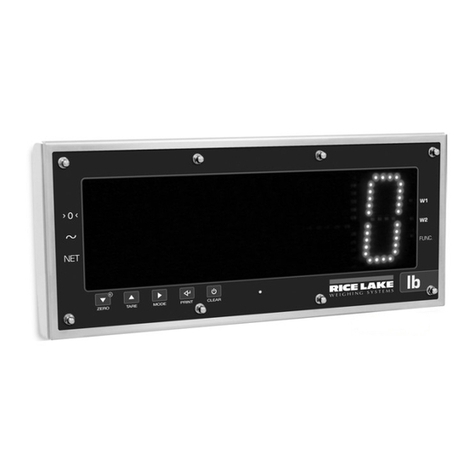
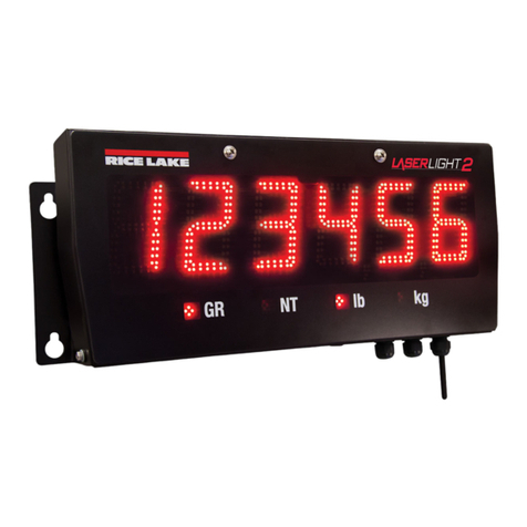
Rice Lake LaserLight3 User manual

LaserLight3® Series
Remote Display
Firmware Version 1
Technical Manual
PN 214748 Rev ADecember 8, 2022

© Rice Lake Weighing Systems. All rights reserved.
Rice Lake Weighing Systems® is a registered trademark of
Rice Lake Weighing Systems.
All other brand or product names within this publication are trademarks or
registered trademarks of their respective companies.
All information contained within this publication is, to the best of our knowledge, complete and
accurate at the time of publication. Rice Lake Weighing Systems reserves the right to make
changes to the technology, features, specifications and design of the equipment without notice.
The most current version of this publication, software, firmware and all other product
updates can be found on our website:
www.ricelake.com

Revision History
© Rice Lake Weighing Systems ● All Rights Reserved 3
Technical training seminars are available through Rice Lake Weighing Systems.
Course descriptions and dates can be viewed at www.ricelake.com/training
or obtained by calling 715-234-9171 and asking for the training department.
Revision History
This section tracks and describes manual revisions for awareness of major updates.
Revision Date Description
A December 8, 2022 Initial manual release with the launch of the product; firmware V1.00.00
Table i. Revision Letter History

Contents
LaserLight3 Remote Display
4 Visit our website www.RiceLake.com
Rice Lake continually offers web-based video training on a growing selection
of product-related topics at no cost. Visit www.ricelake.com/webinars
1.0 Introduction . . . . . . . . . . . . . . . . . . . . . . . . . . . . . . . . . . . . . . . . . . . . . . . . . . . . . . . . . . . . . . . . . . . . . . . . . . . . 7
1.1 Safety . . . . . . . . . . . . . . . . . . . . . . . . . . . . . . . . . . . . . . . . . . . . . . . . . . . . . . . . . . . . . . . . . . . . . . . . . . . . . . . . . . . . . . . . . . . . . 7
1.2 FCC Compliance. . . . . . . . . . . . . . . . . . . . . . . . . . . . . . . . . . . . . . . . . . . . . . . . . . . . . . . . . . . . . . . . . . . . . . . . . . . . . . . . . . . . . 8
1.3 Overview . . . . . . . . . . . . . . . . . . . . . . . . . . . . . . . . . . . . . . . . . . . . . . . . . . . . . . . . . . . . . . . . . . . . . . . . . . . . . . . . . . . . . . . . . . . 8
1.3.1 Standard Features . . . . . . . . . . . . . . . . . . . . . . . . . . . . . . . . . . . . . . . . . . . . . . . . . . . . . . . . . . . . . . . . . . . . . . . . . . . . 8
1.4 Operating Modes. . . . . . . . . . . . . . . . . . . . . . . . . . . . . . . . . . . . . . . . . . . . . . . . . . . . . . . . . . . . . . . . . . . . . . . . . . . . . . . . . . . . . 9
1.5 LaserLight3 Options . . . . . . . . . . . . . . . . . . . . . . . . . . . . . . . . . . . . . . . . . . . . . . . . . . . . . . . . . . . . . . . . . . . . . . . . . . . . . . . . . . 9
2.0 Installation . . . . . . . . . . . . . . . . . . . . . . . . . . . . . . . . . . . . . . . . . . . . . . . . . . . . . . . . . . . . . . . . . . . . . . . . . . . . 10
2.1 Unpacking . . . . . . . . . . . . . . . . . . . . . . . . . . . . . . . . . . . . . . . . . . . . . . . . . . . . . . . . . . . . . . . . . . . . . . . . . . . . . . . . . . . . . . . . . 10
2.2 Product Dimensions . . . . . . . . . . . . . . . . . . . . . . . . . . . . . . . . . . . . . . . . . . . . . . . . . . . . . . . . . . . . . . . . . . . . . . . . . . . . . . . . . 10
2.2.1 Mount Bracket Dimensions . . . . . . . . . . . . . . . . . . . . . . . . . . . . . . . . . . . . . . . . . . . . . . . . . . . . . . . . . . . . . . . . . . . . 11
2.3 Wall Mounting . . . . . . . . . . . . . . . . . . . . . . . . . . . . . . . . . . . . . . . . . . . . . . . . . . . . . . . . . . . . . . . . . . . . . . . . . . . . . . . . . . . . . . 12
2.4 Opening the Enclosure . . . . . . . . . . . . . . . . . . . . . . . . . . . . . . . . . . . . . . . . . . . . . . . . . . . . . . . . . . . . . . . . . . . . . . . . . . . . . . . 13
2.5 Cable Connections . . . . . . . . . . . . . . . . . . . . . . . . . . . . . . . . . . . . . . . . . . . . . . . . . . . . . . . . . . . . . . . . . . . . . . . . . . . . . . . . . . 14
2.5.1 Cord Grips . . . . . . . . . . . . . . . . . . . . . . . . . . . . . . . . . . . . . . . . . . . . . . . . . . . . . . . . . . . . . . . . . . . . . . . . . . . . . . . . . 14
2.5.2 Power Supply Wiring . . . . . . . . . . . . . . . . . . . . . . . . . . . . . . . . . . . . . . . . . . . . . . . . . . . . . . . . . . . . . . . . . . . . . . . . . 15
2.6 CPU Board Connections. . . . . . . . . . . . . . . . . . . . . . . . . . . . . . . . . . . . . . . . . . . . . . . . . . . . . . . . . . . . . . . . . . . . . . . . . . . . . . 16
2.6.1 CPU Board Power Input. . . . . . . . . . . . . . . . . . . . . . . . . . . . . . . . . . . . . . . . . . . . . . . . . . . . . . . . . . . . . . . . . . . . . . . 16
2.6.2 CPU Board Display Power Out . . . . . . . . . . . . . . . . . . . . . . . . . . . . . . . . . . . . . . . . . . . . . . . . . . . . . . . . . . . . . . . . . 16
2.6.3 RS-232 Serial Communications. . . . . . . . . . . . . . . . . . . . . . . . . . . . . . . . . . . . . . . . . . . . . . . . . . . . . . . . . . . . . . . . . 17
2.6.4 RS-485/422 Serial Communications . . . . . . . . . . . . . . . . . . . . . . . . . . . . . . . . . . . . . . . . . . . . . . . . . . . . . . . . . . . . . 17
2.6.5 Digital I/O . . . . . . . . . . . . . . . . . . . . . . . . . . . . . . . . . . . . . . . . . . . . . . . . . . . . . . . . . . . . . . . . . . . . . . . . . . . . . . . . . . 18
2.6.6 Micro USB Device Communications . . . . . . . . . . . . . . . . . . . . . . . . . . . . . . . . . . . . . . . . . . . . . . . . . . . . . . . . . . . . . 18
2.6.7 Ethernet TCP/IP. . . . . . . . . . . . . . . . . . . . . . . . . . . . . . . . . . . . . . . . . . . . . . . . . . . . . . . . . . . . . . . . . . . . . . . . . . . . . 19
2.6.8 20 mA . . . . . . . . . . . . . . . . . . . . . . . . . . . . . . . . . . . . . . . . . . . . . . . . . . . . . . . . . . . . . . . . . . . . . . . . . . . . . . . . . . . . 20
2.6.9 Keypad and Ambient Light Sensor . . . . . . . . . . . . . . . . . . . . . . . . . . . . . . . . . . . . . . . . . . . . . . . . . . . . . . . . . . . . . . 20
2.6.10 RF Interference . . . . . . . . . . . . . . . . . . . . . . . . . . . . . . . . . . . . . . . . . . . . . . . . . . . . . . . . . . . . . . . . . . . . . . . . . . . . . 20
2.7 CPU Board Features. . . . . . . . . . . . . . . . . . . . . . . . . . . . . . . . . . . . . . . . . . . . . . . . . . . . . . . . . . . . . . . . . . . . . . . . . . . . . . . . . 21
2.7.1 Status LEDs . . . . . . . . . . . . . . . . . . . . . . . . . . . . . . . . . . . . . . . . . . . . . . . . . . . . . . . . . . . . . . . . . . . . . . . . . . . . . . . . 21
2.7.2 CPU Board Jumpers . . . . . . . . . . . . . . . . . . . . . . . . . . . . . . . . . . . . . . . . . . . . . . . . . . . . . . . . . . . . . . . . . . . . . . . . . 22
2.7.3 CPU Board Switches . . . . . . . . . . . . . . . . . . . . . . . . . . . . . . . . . . . . . . . . . . . . . . . . . . . . . . . . . . . . . . . . . . . . . . . . . 23
2.8 Parts Kit. . . . . . . . . . . . . . . . . . . . . . . . . . . . . . . . . . . . . . . . . . . . . . . . . . . . . . . . . . . . . . . . . . . . . . . . . . . . . . . . . . . . . . . . . . . 23
2.9 Replacement Parts . . . . . . . . . . . . . . . . . . . . . . . . . . . . . . . . . . . . . . . . . . . . . . . . . . . . . . . . . . . . . . . . . . . . . . . . . . . . . . . . . . 24
2.9.1 LaserLight3 Assembly Parts . . . . . . . . . . . . . . . . . . . . . . . . . . . . . . . . . . . . . . . . . . . . . . . . . . . . . . . . . . . . . . . . . . . 24
2.9.2 Front Door Assembly Parts . . . . . . . . . . . . . . . . . . . . . . . . . . . . . . . . . . . . . . . . . . . . . . . . . . . . . . . . . . . . . . . . . . . . 25
2.9.3 Cabinet Assembly Parts. . . . . . . . . . . . . . . . . . . . . . . . . . . . . . . . . . . . . . . . . . . . . . . . . . . . . . . . . . . . . . . . . . . . . . . 27
3.0 Operation . . . . . . . . . . . . . . . . . . . . . . . . . . . . . . . . . . . . . . . . . . . . . . . . . . . . . . . . . . . . . . . . . . . . . . . . . . . . . 28
3.1 Front Panel Display. . . . . . . . . . . . . . . . . . . . . . . . . . . . . . . . . . . . . . . . . . . . . . . . . . . . . . . . . . . . . . . . . . . . . . . . . . . . . . . . . . 28
3.2 Keypad . . . . . . . . . . . . . . . . . . . . . . . . . . . . . . . . . . . . . . . . . . . . . . . . . . . . . . . . . . . . . . . . . . . . . . . . . . . . . . . . . . . . . . . . . . . 29
3.3 Menu Element Overview. . . . . . . . . . . . . . . . . . . . . . . . . . . . . . . . . . . . . . . . . . . . . . . . . . . . . . . . . . . . . . . . . . . . . . . . . . . . . . 30
3.3.1 Menu with Selectable Item. . . . . . . . . . . . . . . . . . . . . . . . . . . . . . . . . . . . . . . . . . . . . . . . . . . . . . . . . . . . . . . . . . . . . 30
3.3.2 Menu and Read Only Message . . . . . . . . . . . . . . . . . . . . . . . . . . . . . . . . . . . . . . . . . . . . . . . . . . . . . . . . . . . . . . . . . 30
3.3.3 Menu and Text Editable Parameter . . . . . . . . . . . . . . . . . . . . . . . . . . . . . . . . . . . . . . . . . . . . . . . . . . . . . . . . . . . . . . 31
3.4 Frequently Used Software Functions . . . . . . . . . . . . . . . . . . . . . . . . . . . . . . . . . . . . . . . . . . . . . . . . . . . . . . . . . . . . . . . . . . . . 31
3.4.1 Edit Time . . . . . . . . . . . . . . . . . . . . . . . . . . . . . . . . . . . . . . . . . . . . . . . . . . . . . . . . . . . . . . . . . . . . . . . . . . . . . . . . . . 31
3.4.2 Edit Date . . . . . . . . . . . . . . . . . . . . . . . . . . . . . . . . . . . . . . . . . . . . . . . . . . . . . . . . . . . . . . . . . . . . . . . . . . . . . . . . . . 32

Contents
© Rice Lake Weighing Systems ● All Rights Reserved 5
Technical training seminars are available through Rice Lake Weighing Systems.
Course descriptions and dates can be viewed at www.ricelake.com/training
or obtained by calling 715-234-9171 and asking for the training department.
3.4.3 Displaying Time and Date . . . . . . . . . . . . . . . . . . . . . . . . . . . . . . . . . . . . . . . . . . . . . . . . . . . . . . . . . . . . . . . . . . . . . 32
3.4.4 View Ethernet and Wi-Fi Media Access Control (MAC) IDs. . . . . . . . . . . . . . . . . . . . . . . . . . . . . . . . . . . . . . . . . . . . 33
3.4.5 View Version . . . . . . . . . . . . . . . . . . . . . . . . . . . . . . . . . . . . . . . . . . . . . . . . . . . . . . . . . . . . . . . . . . . . . . . . . . . . . . . 33
3.4.6 Reset Configuration . . . . . . . . . . . . . . . . . . . . . . . . . . . . . . . . . . . . . . . . . . . . . . . . . . . . . . . . . . . . . . . . . . . . . . . . . . 34
3.4.7 Change Brightness Intensity . . . . . . . . . . . . . . . . . . . . . . . . . . . . . . . . . . . . . . . . . . . . . . . . . . . . . . . . . . . . . . . . . . . 34
3.4.8 Change Display Color . . . . . . . . . . . . . . . . . . . . . . . . . . . . . . . . . . . . . . . . . . . . . . . . . . . . . . . . . . . . . . . . . . . . . . . . 35
4.0 Remote Display Configuration . . . . . . . . . . . . . . . . . . . . . . . . . . . . . . . . . . . . . . . . . . . . . . . . . . . . . . . . . . . . 36
4.1 Configure Display Type. . . . . . . . . . . . . . . . . . . . . . . . . . . . . . . . . . . . . . . . . . . . . . . . . . . . . . . . . . . . . . . . . . . . . . . . . . . . . . . 36
4.2 Automatic Configuration . . . . . . . . . . . . . . . . . . . . . . . . . . . . . . . . . . . . . . . . . . . . . . . . . . . . . . . . . . . . . . . . . . . . . . . . . . . . . . 37
4.2.1 Automatic Baud Configuration . . . . . . . . . . . . . . . . . . . . . . . . . . . . . . . . . . . . . . . . . . . . . . . . . . . . . . . . . . . . . . . . . . 37
4.2.2 Auto-Learn and Data String Recognition . . . . . . . . . . . . . . . . . . . . . . . . . . . . . . . . . . . . . . . . . . . . . . . . . . . . . . . . . . 38
4.3 Manual Mode . . . . . . . . . . . . . . . . . . . . . . . . . . . . . . . . . . . . . . . . . . . . . . . . . . . . . . . . . . . . . . . . . . . . . . . . . . . . . . . . . . . . . . 40
4.3.1 Enable Manual Mode . . . . . . . . . . . . . . . . . . . . . . . . . . . . . . . . . . . . . . . . . . . . . . . . . . . . . . . . . . . . . . . . . . . . . . . . . 40
4.3.2 Configuring Manual Mode Parameters . . . . . . . . . . . . . . . . . . . . . . . . . . . . . . . . . . . . . . . . . . . . . . . . . . . . . . . . . . . 41
4.3.3 MnlMVal (Manual Mode Validation) Operation . . . . . . . . . . . . . . . . . . . . . . . . . . . . . . . . . . . . . . . . . . . . . . . . . . . . . 49
4.4 Demand Print Displaying. . . . . . . . . . . . . . . . . . . . . . . . . . . . . . . . . . . . . . . . . . . . . . . . . . . . . . . . . . . . . . . . . . . . . . . . . . . . . . 50
4.5 Serial Commands . . . . . . . . . . . . . . . . . . . . . . . . . . . . . . . . . . . . . . . . . . . . . . . . . . . . . . . . . . . . . . . . . . . . . . . . . . . . . . . . . . . 50
4.5.1 Remote Display Command Format:. . . . . . . . . . . . . . . . . . . . . . . . . . . . . . . . . . . . . . . . . . . . . . . . . . . . . . . . . . . . . . 50
4.5.2 Advanced Display Message (DM) Commands. . . . . . . . . . . . . . . . . . . . . . . . . . . . . . . . . . . . . . . . . . . . . . . . . . . . . . 51
5.0 Configuration . . . . . . . . . . . . . . . . . . . . . . . . . . . . . . . . . . . . . . . . . . . . . . . . . . . . . . . . . . . . . . . . . . . . . . . . . . 53
5.1 Main Menu . . . . . . . . . . . . . . . . . . . . . . . . . . . . . . . . . . . . . . . . . . . . . . . . . . . . . . . . . . . . . . . . . . . . . . . . . . . . . . . . . . . . . . . . 53
5.2 Setup Menu. . . . . . . . . . . . . . . . . . . . . . . . . . . . . . . . . . . . . . . . . . . . . . . . . . . . . . . . . . . . . . . . . . . . . . . . . . . . . . . . . . . . . . . . 54
5.2.1 Communications Menu . . . . . . . . . . . . . . . . . . . . . . . . . . . . . . . . . . . . . . . . . . . . . . . . . . . . . . . . . . . . . . . . . . . . . . . 54
5.2.2 Format Menu . . . . . . . . . . . . . . . . . . . . . . . . . . . . . . . . . . . . . . . . . . . . . . . . . . . . . . . . . . . . . . . . . . . . . . . . . . . . . . . 59
5.2.3 Program Menu . . . . . . . . . . . . . . . . . . . . . . . . . . . . . . . . . . . . . . . . . . . . . . . . . . . . . . . . . . . . . . . . . . . . . . . . . . . . . . 60
5.2.4 Stream Format Menu . . . . . . . . . . . . . . . . . . . . . . . . . . . . . . . . . . . . . . . . . . . . . . . . . . . . . . . . . . . . . . . . . . . . . . . . . 62
5.2.5 Digio (Digital I/O) Menu . . . . . . . . . . . . . . . . . . . . . . . . . . . . . . . . . . . . . . . . . . . . . . . . . . . . . . . . . . . . . . . . . . . . . . . 63
5.2.6 Remote Menu. . . . . . . . . . . . . . . . . . . . . . . . . . . . . . . . . . . . . . . . . . . . . . . . . . . . . . . . . . . . . . . . . . . . . . . . . . . . . . . 63
5.3 MAC ID . . . . . . . . . . . . . . . . . . . . . . . . . . . . . . . . . . . . . . . . . . . . . . . . . . . . . . . . . . . . . . . . . . . . . . . . . . . . . . . . . . . . . . . . . . . 65
5.4 Test Menu . . . . . . . . . . . . . . . . . . . . . . . . . . . . . . . . . . . . . . . . . . . . . . . . . . . . . . . . . . . . . . . . . . . . . . . . . . . . . . . . . . . . . . . . . 66
5.5 Time Menu . . . . . . . . . . . . . . . . . . . . . . . . . . . . . . . . . . . . . . . . . . . . . . . . . . . . . . . . . . . . . . . . . . . . . . . . . . . . . . . . . . . . . . . . 67
5.6 Date Menu. . . . . . . . . . . . . . . . . . . . . . . . . . . . . . . . . . . . . . . . . . . . . . . . . . . . . . . . . . . . . . . . . . . . . . . . . . . . . . . . . . . . . . . . . 67
5.7 Version . . . . . . . . . . . . . . . . . . . . . . . . . . . . . . . . . . . . . . . . . . . . . . . . . . . . . . . . . . . . . . . . . . . . . . . . . . . . . . . . . . . . . . . . . . . 67
6.0 Revolution . . . . . . . . . . . . . . . . . . . . . . . . . . . . . . . . . . . . . . . . . . . . . . . . . . . . . . . . . . . . . . . . . . . . . . . . . . . . 68
6.1 Connecting to LaserLight3 . . . . . . . . . . . . . . . . . . . . . . . . . . . . . . . . . . . . . . . . . . . . . . . . . . . . . . . . . . . . . . . . . . . . . . . . . . . . 68
6.2 Saving and Transferring Data . . . . . . . . . . . . . . . . . . . . . . . . . . . . . . . . . . . . . . . . . . . . . . . . . . . . . . . . . . . . . . . . . . . . . . . . . . 68
6.2.1 Saving LaserLight3 Data to a PC. . . . . . . . . . . . . . . . . . . . . . . . . . . . . . . . . . . . . . . . . . . . . . . . . . . . . . . . . . . . . . . . 68
6.2.2 Downloading Configuration Data from PC to LaserLight3 . . . . . . . . . . . . . . . . . . . . . . . . . . . . . . . . . . . . . . . . . . . . . 68
6.3 Updating Firmware . . . . . . . . . . . . . . . . . . . . . . . . . . . . . . . . . . . . . . . . . . . . . . . . . . . . . . . . . . . . . . . . . . . . . . . . . . . . . . . . . . 69
7.0 EDP Commands. . . . . . . . . . . . . . . . . . . . . . . . . . . . . . . . . . . . . . . . . . . . . . . . . . . . . . . . . . . . . . . . . . . . . . . . 70
7.1 Key Press Commands . . . . . . . . . . . . . . . . . . . . . . . . . . . . . . . . . . . . . . . . . . . . . . . . . . . . . . . . . . . . . . . . . . . . . . . . . . . . . . . 70
7.2 Reporting Commands . . . . . . . . . . . . . . . . . . . . . . . . . . . . . . . . . . . . . . . . . . . . . . . . . . . . . . . . . . . . . . . . . . . . . . . . . . . . . . . . 71
7.3 Reset Configuration Command. . . . . . . . . . . . . . . . . . . . . . . . . . . . . . . . . . . . . . . . . . . . . . . . . . . . . . . . . . . . . . . . . . . . . . . . . 71
7.4 LaserLight3 Commands . . . . . . . . . . . . . . . . . . . . . . . . . . . . . . . . . . . . . . . . . . . . . . . . . . . . . . . . . . . . . . . . . . . . . . . . . . . . . . 72
7.4.1 Learn or Manual Mode commands . . . . . . . . . . . . . . . . . . . . . . . . . . . . . . . . . . . . . . . . . . . . . . . . . . . . . . . . . . . . . . 72
7.4.2 Additional LaserLight3 commands. . . . . . . . . . . . . . . . . . . . . . . . . . . . . . . . . . . . . . . . . . . . . . . . . . . . . . . . . . . . . . . 73
7.5 Serial Port Setting Commands . . . . . . . . . . . . . . . . . . . . . . . . . . . . . . . . . . . . . . . . . . . . . . . . . . . . . . . . . . . . . . . . . . . . . . . . . 73

LaserLight3 Remote Display
6 Visit our website www.RiceLake.com
Rice Lake continually offers web-based video training on a growing selection
of product-related topics at no cost. Visit www.ricelake.com/webinars
7.5.1 Serial Ports. . . . . . . . . . . . . . . . . . . . . . . . . . . . . . . . . . . . . . . . . . . . . . . . . . . . . . . . . . . . . . . . . . . . . . . . . . . . . . . . . 73
7.6 Ethernet and USB Setting Commands . . . . . . . . . . . . . . . . . . . . . . . . . . . . . . . . . . . . . . . . . . . . . . . . . . . . . . . . . . . . . . . . . . . 74
7.7 Wi-Fi Setting Commands . . . . . . . . . . . . . . . . . . . . . . . . . . . . . . . . . . . . . . . . . . . . . . . . . . . . . . . . . . . . . . . . . . . . . . . . . . . . . 74
7.8 Program Commands. . . . . . . . . . . . . . . . . . . . . . . . . . . . . . . . . . . . . . . . . . . . . . . . . . . . . . . . . . . . . . . . . . . . . . . . . . . . . . . . . 75
7.9 Digital I/O Command. . . . . . . . . . . . . . . . . . . . . . . . . . . . . . . . . . . . . . . . . . . . . . . . . . . . . . . . . . . . . . . . . . . . . . . . . . . . . . . . . 75
8.0 Maintenance . . . . . . . . . . . . . . . . . . . . . . . . . . . . . . . . . . . . . . . . . . . . . . . . . . . . . . . . . . . . . . . . . . . . . . . . . . . 76
8.1 Maintenance Checkpoints. . . . . . . . . . . . . . . . . . . . . . . . . . . . . . . . . . . . . . . . . . . . . . . . . . . . . . . . . . . . . . . . . . . . . . . . . . . . . 76
8.2 Field Wiring . . . . . . . . . . . . . . . . . . . . . . . . . . . . . . . . . . . . . . . . . . . . . . . . . . . . . . . . . . . . . . . . . . . . . . . . . . . . . . . . . . . . . . . . 76
8.3 Troubleshooting Tips. . . . . . . . . . . . . . . . . . . . . . . . . . . . . . . . . . . . . . . . . . . . . . . . . . . . . . . . . . . . . . . . . . . . . . . . . . . . . . . . . 76
8.4 Removing Front Door . . . . . . . . . . . . . . . . . . . . . . . . . . . . . . . . . . . . . . . . . . . . . . . . . . . . . . . . . . . . . . . . . . . . . . . . . . . . . . . . 77
8.5 Battery Replacement. . . . . . . . . . . . . . . . . . . . . . . . . . . . . . . . . . . . . . . . . . . . . . . . . . . . . . . . . . . . . . . . . . . . . . . . . . . . . . . . . 79
8.6 CPU Board Replacement . . . . . . . . . . . . . . . . . . . . . . . . . . . . . . . . . . . . . . . . . . . . . . . . . . . . . . . . . . . . . . . . . . . . . . . . . . . . . 80
8.7 LED Display Replacement . . . . . . . . . . . . . . . . . . . . . . . . . . . . . . . . . . . . . . . . . . . . . . . . . . . . . . . . . . . . . . . . . . . . . . . . . . . . 82
8.8 Test Functions. . . . . . . . . . . . . . . . . . . . . . . . . . . . . . . . . . . . . . . . . . . . . . . . . . . . . . . . . . . . . . . . . . . . . . . . . . . . . . . . . . . . . . 86
8.8.1 Digital Output Test . . . . . . . . . . . . . . . . . . . . . . . . . . . . . . . . . . . . . . . . . . . . . . . . . . . . . . . . . . . . . . . . . . . . . . . . . . . 86
8.8.2 Digital Input Test . . . . . . . . . . . . . . . . . . . . . . . . . . . . . . . . . . . . . . . . . . . . . . . . . . . . . . . . . . . . . . . . . . . . . . . . . . . . 86
8.8.3 Loop-back Test . . . . . . . . . . . . . . . . . . . . . . . . . . . . . . . . . . . . . . . . . . . . . . . . . . . . . . . . . . . . . . . . . . . . . . . . . . . . . 87
9.0 Appendix . . . . . . . . . . . . . . . . . . . . . . . . . . . . . . . . . . . . . . . . . . . . . . . . . . . . . . . . . . . . . . . . . . . . . . . . . . . . . 88
9.1 Error Messages. . . . . . . . . . . . . . . . . . . . . . . . . . . . . . . . . . . . . . . . . . . . . . . . . . . . . . . . . . . . . . . . . . . . . . . . . . . . . . . . . . . . . 88
9.2 Parameter Abbreviation List . . . . . . . . . . . . . . . . . . . . . . . . . . . . . . . . . . . . . . . . . . . . . . . . . . . . . . . . . . . . . . . . . . . . . . . . . . . 89
9.3 Non-Printable Characters . . . . . . . . . . . . . . . . . . . . . . . . . . . . . . . . . . . . . . . . . . . . . . . . . . . . . . . . . . . . . . . . . . . . . . . . . . . . . 90
9.4 ZZ EDP Command . . . . . . . . . . . . . . . . . . . . . . . . . . . . . . . . . . . . . . . . . . . . . . . . . . . . . . . . . . . . . . . . . . . . . . . . . . . . . . . . . . 93
9.5 Auto-Learn Supported Data Formats . . . . . . . . . . . . . . . . . . . . . . . . . . . . . . . . . . . . . . . . . . . . . . . . . . . . . . . . . . . . . . . . . . . . 93
9.6 Continuous Data (Stream) Output Formats. . . . . . . . . . . . . . . . . . . . . . . . . . . . . . . . . . . . . . . . . . . . . . . . . . . . . . . . . . . . . . . . 94
9.6.1 Fixed Format Options: . . . . . . . . . . . . . . . . . . . . . . . . . . . . . . . . . . . . . . . . . . . . . . . . . . . . . . . . . . . . . . . . . . . . . . . . 94
9.6.2 Rice Lake Weighing Systems Stream Format . . . . . . . . . . . . . . . . . . . . . . . . . . . . . . . . . . . . . . . . . . . . . . . . . . . . . . 94
9.6.3 Cardinal Stream Format. . . . . . . . . . . . . . . . . . . . . . . . . . . . . . . . . . . . . . . . . . . . . . . . . . . . . . . . . . . . . . . . . . . . . . . 94
9.6.4 Avery Weigh-Tronix Stream Format. . . . . . . . . . . . . . . . . . . . . . . . . . . . . . . . . . . . . . . . . . . . . . . . . . . . . . . . . . . . . . 95
9.6.5 Mettler Toledo Stream Format . . . . . . . . . . . . . . . . . . . . . . . . . . . . . . . . . . . . . . . . . . . . . . . . . . . . . . . . . . . . . . . . . . 95
9.6.6 Custom Stream Format Tokens. . . . . . . . . . . . . . . . . . . . . . . . . . . . . . . . . . . . . . . . . . . . . . . . . . . . . . . . . . . . . . . . . 96
10.0 Specifications . . . . . . . . . . . . . . . . . . . . . . . . . . . . . . . . . . . . . . . . . . . . . . . . . . . . . . . . . . . . . . . . . . . . . . . . . 98

Introduction
© Rice Lake Weighing Systems ● All Rights Reserved 7
1.0 Introduction
This manual is intended for use by service technicians responsible for installing and servicing the LaserLight3 Remote Display.
Remote display configuration is detailed in Section 4.0 on page 36. Configuration of LaserLight3 can be accomplished using
the Revolution® configuration utility or the front panel keys. See Section 5.0 on page 53 for information about configuration.
Manuals and additional resources are available from Rice Lake Weighing Systems at www.ricelake.com/manuals
Warranty information can be found at www.ricelake.com/warranties
1.1 Safety
Safety Definitions:
DANGER: Indicates an imminently hazardous situation that, if not avoided, will result in death or serious injury. Includes
hazards that are exposed when guards are removed.
WARNING: Indicates a potentially hazardous situation that, if not avoided, could result in serious injury or death. Includes
hazards that are exposed when guards are removed.
CAUTION: Indicates a potentially hazardous situation that, if not avoided, could result in minor or moderate injury.
IMPORTANT: Indicates information about procedures that, if not observed, could result in damage to equipment or
corruption to and loss of data.
General Safety
Do not operate or work on this equipment unless this manual has been read and all instructions are understood.
Failure to follow the instructions or heed the warnings could result in injury or death. Contact any Rice Lake
Weighing Systems dealer for replacement manuals.
WARNING
Failure to heed could result in serious injury or death.
Some procedures described in this manual require work inside the indicator enclosure. These procedures are to be performed by
qualified service personnel only.
Do not allow minors (children) or inexperienced persons to operate the LaserLight3.
Do not place fingers into slots or possible pinch points.
Do not use any load-bearing component that is worn beyond 5% of the original dimension.
Do not use this product if any of the components are cracked.
Do not make alterations or modifications to the unit.
Do not remove or obstruct view of warning label (Figure 1-1).
Before opening the unit, ensure the power cord is disconnected from the outlet.
Figure 1-1. Safety Label (PN 16861)
WARNING!
HIGH VOLTAGE
DISCONNECT POWER BEFORE SERVICING

LaserLight3 Remote Display
8 Visit our website www.RiceLake.com
1.2 FCC Compliance
United States
This equipment has been tested and found to comply with the limits for a Class A digital device, pursuant to Part 15 of the FCC
Rules. These limits are designed to provide reasonable protection against harmful interference when the equipment is operated
in a commercial environment. This equipment generates, uses and can radiate radio frequency energy and, if not installed and
used in accordance with the instruction manual, may cause harmful interference to radio communications. Operation of this
equipment in a residential area is likely to cause harmful interference in which case the user will be required to correct the
interference at his own expense.
Canada
This digital apparatus does not exceed the Class A limits for radio noise emissions from digital apparatus set out in the Radio
Interference Regulations of the Canadian Department of Communications.
Le présent appareil numérique n'émet pas de bruits radioélectriques dépassant les limites applicables aux appareils
numériques de la Class A prescites dans le Règlement sur le brouillage radioélectrique edicté par le ministère des
Communications du Canada.
1.3 Overview
The LaserLight3 operates with most digital weight indicators, host computers, and peripherals via 20 mA current loop, RS-232,
RS-422 full and half duplex, Ethernet (wired TCP/IP), Wi-Fi or Radio connections. It displays a 5 in weight, 4 in weight with
traffic symbols, 2-line message, or quarantine messages with color selections. The LaserLight3 includes a photo sensor tha
monitors ambient light and automatically adjusts the LaserLight3 display between day and night settings.
The LaserLight3 enclosure provides easy access to internal components, the front door swings down for setup and service. A
keypad is installed on the front door which makes navigating and configuring options convenient.
1.3.1 Standard Features
Standard features include:
• Two 64 X 32 Led Displays (128 x 32 Combined)
• Color Selection (red, yellow, green, blue, magenta, cyan or white)
• Auto-Learn mode
• IP66 enclosure
• Hinged front door
• Keypad
• Adjustable day and night brightness intensity
• Software selectable time and date (when the displayed weight is at zero)
• Non-glare contrast filtered lens
• Mirror (reverse image) feature
• RS-232, RS-422, 20 mA, and Ethernet (wired TCP/IP) communications
• Auto sensing 115/240 VAC power supply
• VESA flat-wall mount or side-mounting flange
• Gore-Tex® breather vent inhibits internal moisture buildup

Introduction
© Rice Lake Weighing Systems ● All Rights Reserved 9
1.4 Operating Modes
Modes available to the LaserLight3 remote display are detailed in Table 1-1.
1.5 LaserLight3 Options
Options for the LaserLight3 include:
• Flange Pole mount kit (see PN 75856)
• VESA Pole mount kits (see PN 212745)
• Sunshade Visor kit (see PN 214693)
• Wi-Fi (factory installed, PN 209118)
• ConnexLink (see PN 212753)
Mode Description
Remote Display Mode Remote Display mode is the primary mode of the device. The LaserLight3 displays data that is received
from an external source, such as an indicator
Menu Mode Menu mode is accessible by pressing on the front panel. Access to the Audit, Setpoint,
Accumulator, Tare, Time, Date, MAC ID, and Version menus is available when in Menu mode
Setup Mode Many of the procedures described in this manual, require the indicator to be in Setup mode.
See Section 2.7.2 on page 22 for the procedure to enter Setup mode and the parameters available
Table 1-1. Operating Mode Descriptions
MENU

LaserLight3 Remote Display
10 Visit our website www.RiceLake.com
2.0 Installation
This section provides an overview of LaserLight3 Series installation, AC wiring, CPU board connections, replacement parts.
WARNING: The LaserLight3 has no on/off switch. Before opening the unit, ensure the power cord is disconnected from the
power outlet.
Use a grounding wrist strap to protect components from electrostatic discharge (ESD) when working inside the enclosure.
2.1 Unpacking
Immediately after unpacking, visually inspect the LaserLight3 for damage. If parts were damaged in shipment, notify Rice Lake
Weighing Systems and the shipper immediately.
The shipping carton contains the following components:
• LaserLight3
• Mounting bracket or pole mount
• Documentation
2.2 Product Dimensions
Figure 2-1 displays exterior LaserLight3 dimensions.
Figure 2-1. LaserLight3 Dimensions Profile and Top
Item Inches Millimeters
A 8.73 222
B 10.10 257
C 10.34 262
D 5.00 127
E 23.00 584
F 6.19 157
Table 2-1. LaseLight3 Dimensions
BA
C
D
F
E

Installation
© Rice Lake Weighing Systems ● All Rights Reserved 11
2.2.1 Mount Bracket Dimensions
Figure 2-2 displays LaserLight3 the mounting bracket dimensions.
Figure 2-2. Mounting Bracket Dimensions
Item Inches Millimeters
A 6.00 152
B 8.00 203
C 16.00 406
D 23.00 584
E 24.76 629
F 0.39 10
G 0.76 19
Table 2-2. LaseLight3 Dimensions
A
G
B
C
D
E
F

LaserLight3 Remote Display
12 Visit our website www.RiceLake.com
2.3 Wall Mounting
LaserLight3 can be mounted to a flat surface in two ways:
• Using 0.39 in (10 mm) - 0.76 in (19 mm) keyholes
• Using 100 x 100 or 200 x 200 VESA mounting holes
Figure 2-3. Bracket with VESA Mounting Holes Identified
NOTE: An optional pole mounting kit is required when installing the remote display on a pole.
Item Description Inches Millimeters
A VESA 200 Mount Standard 7.87 200
B VESA Mount Holes (M4 0.07 X 10mm) 0.19 5
C VESA 100 Mount Standard 3.94 100
D Upper Keyhole Mount 0.39 10
E Lower Keyhole Mount 0.75 19
Table 2-3. Mounting Dimensions
C
AB
E
D

Installation
© Rice Lake Weighing Systems ● All Rights Reserved 13
2.4 Opening the Enclosure
Perform the following to open the enclosure.
WARNING: The LaserLight3 has no on/off switch. Before opening the unit, ensure the power cord is disconnected from the
power outlet.
1. If necessary, remove wire or tamper proof seal.
2. Loosen the two captive screws located on the front of the enclosure.
Figure 2-4. Front Door Fasteners and Wire Seal Location
3. Pull the hinged display outward to open the enclosure.
Figure 2-5. LaserLight3 Open
4. Reverse the procedure to close the enclosure.
Tamper Disc
Captive Screws

LaserLight3 Remote Display
14 Visit our website www.RiceLake.com
2.5 Cable Connections
The LaserLight3 arrives pre-wired with connections from the CPU board to the display boards, CPU board to keypad, CPU
board to power supply and power cord to power supply.
A data source from an external device must be received by the Remote Display via RS-232 (Section 2.6.3 on page 17), RS-
485/422 (Section 2.6.8 on page 20
)
, 20 mA (Section 2.6.4 on page 17
)
, Ethernet (Section 2.6.7 on page 19
)
or Wi-Fi (factory
installed option).
2.5.1 Cord Grips
The LaserLight3 remote display provides three cord grips located on the underside of the enclosure; one for the supplied A/C
power cord and two for load cell or communication cables. Cable plugs are included in the parts kit and must be installed in
open cord grips to prevent moisture from entering the enclosure. See the following sections to install cables as required for the
application.
IMPORTANT: Ensure stripped portion of cables are entirely inside cord grips. Properly seal cord grips to prevent moisture
damage inside of the enclosure. Cable plugs must be installed in unused cord grips. Cord grips have a clamping range of
0.197-0.472 in (5.0-12.0 mm).
Figure 2-6. Cord Grip Layout
Power Cable
Cord grips for Communication
Cables or DIOs
Mounting Location for
optional Wi-Fi or
ConnexLink Antenna

Installation
© Rice Lake Weighing Systems ● All Rights Reserved 15
2.5.2 Power Supply Wiring
The LaserLight3 AC power supply is mounted inside the enclosure and supplies power to the CPU board. AC wiring runs
through a cord grip to the power supply.
Figure 2-7. Power Supply Wiring
NOTE: The far left wire illustrated in Figure 2-7 is a ground attached to power supply mounting plate and enclosure.
Refer to Table 2-4 for power supply input wiring connections.
Refer to Table 2-4 for power supply output connections.
Power Supply
Label Wire Color Voltage Input
AC (L) Line Brown or Black 115 or 240 VAC at 50/60 hz.
AC (N) Neutral Blue or White 0
GRD Ground Green/Yellow 0
Table 2-4. Power Supply Input Connections
Power Supply
Label Wire Color Voltage Output CPU Board Connector
-V0 – – – –
-V0 Ground Black 0 J14 P2
+V0 Line Red 12 VDC
(10.2 to 13.8 VDC tolerance) J14 P1
+V0 – – – –
Table 2-5. Power Supply Power Output Connections

LaserLight3 Remote Display
16 Visit our website www.RiceLake.com
2.6 CPU Board Connections
Figure 2-8 illustrates location of cable connections on the CPU board.
Figure 2-8. LaserLight3 CPU Board
2.6.1 CPU Board Power Input
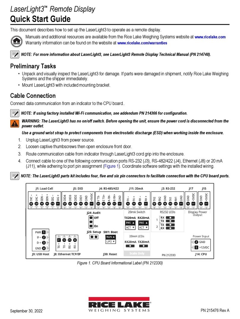
J14 receives power from the AC power supply to power the CPU board. See Figure 2-9 for the pin assignments for the J14
connector.
Figure 2-9. CPU Board Power In Connector (J14)
2.6.2 CPU Board Display Power Out
J15 and J17 supplies display LED boards with power. See Figure 2-10 for the pin assignments for the J15 and J17 connectors.
Figure 2-10. CPU Board Display Power Out Connectors (J15 and J17)
Power In (J14)
20 mA (J11) RS-232 (J3)
RS-485/RS-422 (J4)
DIO (J5)
Micro USB (J7)
Ethernet (J8)
Keypad (J16)
Optional Wi-Fi Card (J12)
Display Power Output CH 1 (J15)
Display Power Output CH 2 (J17)
3V lithium CR2032
Battery (PN 71408)
CPU Board Connector Pin Assignment Signal
J14 1 + 12 VDC
(10.2 to 13.8 VDC tolerance)
2 GND
CPU Board Connector Pin Assignment Signal
J15 CH1 Display Power Output 1 + 5VDC
(4.85 to 5.05 VDC tolerance)
2 GND
J17 CH 2 Display Power Output 1 + 5VDC
(4.85 to 5.05 VDC tolerance)
2 GND

Installation
© Rice Lake Weighing Systems ● All Rights Reserved 17
2.6.3 RS-232 Serial Communications
The J3 connector (Section 2.7 on page 21) is intended to provide a connection point for the RS-232 serial communications.
Two RS-232 ports are available. See Figure 2-11 for the pin assignments for the J3 connector.
Figure 2-11. CPU Board RS-232 Connector (J3)
2.6.4 RS-485/422 Serial Communications
The J4 connector (Section 2.7 on page 21) is intended to provide a connection point for the RS-485/422 serial communications.
Both full duplex (four-wire) and half duplex (two-wire) are supported through the J4 connector. See Figure 2-12 for the pin
assignments for the J4 connector.
Figure 2-12. CPU Board RS-485/422 Connector (J4)
Connector Pin RS232-1 RS232-2
J3 1 GND –
2 RX1 –
3 TX1 –
4 – GND
5 – RX2
6 – TX2
Connector Pin 4-Wire (Full Duplex) 2-Wire (Half Duplex)
J4 1 GND GND
2 RX
-
(B)
–
3 RX+ (A)
–
4 TX
-
(Z) TX / RX
-
5 TX+ (Y) TX / RX+

LaserLight3 Remote Display
18 Visit our website www.RiceLake.com
2.6.5 Digital I/O
The Digital I/O port, J5 connector (Section 2.7 on page 21) can be configured as an input or an output.
Digital inputs can be set to provide many functions, including most keypad functions except MENU. Digital inputs are active low
(0 VDC) and inactive high (5 VDC). Use the Digital I/O menu to configure the digital inputs.
Digital outputs are used to control relays which drive other equipment. Outputs are designed to sink, rather than source current.
Each output is an open collector circuit, capable of sinking 24 mA (max) when active. Digital outputs are active when low or at 0
VDC, with reference to the 5 VDC supply.
Use the Digital I/O menu to set the function of the Digital I/O pins to OUTPUT and then use the Setpoints menu to configure the
digital outputs. See Figure 2-13 for the pin assignments for the J5 connector.
NOTE: An output is wired to ground (P2) and the first available DIO pin, while an input is wired to +5VDC (P1) and first
available DIO pin.
Figure 2-13. CPU Board DIO Connector (J5)
2.6.6 Micro USB Device Communications
The Micro USB port, J7 connector, is intended to be connected to a PC only. It appears as a Virtual COM Port and is assigned
a “COMx” designation. Applications communicate through the port like a standard RS-232 communications port.
With the PC and LaserLight3 powered on, connect a USB cable from the PC to the micro USB connector (J7) on the LaserLight3.
A new COM Port designation is assigned for each physical USB port the LaserLight3 is connected to on the PC.
WARNING: Use a grounding wrist strap to protect components from electrostatic discharge (ESD) when working inside the
enclosure or on the front door.
For example, if the PC has four physical COM Ports with two are in use, they most likely are designated COM1 and COM2.
When connecting the LaserLight3 to a USB port on the PC, it is assigned the next available port designation, or in this case,
COM3. When plugging into the same physical USB port on the PC, the port designation is again COM3. If plugging into another
physical USB port on the PC, it is assigned the next available designation, in this case COM4.
Use Windows® Device Manager to determine the COM Port designation which was assigned to the USB port, or open the
application to be used with the LaserLight3, such as Revolution, to see which ports are available.
Configuration of the Micro USB port is done in the USB sub-menu under Communication in Setup mode. If Remote In is set,
other features (such as sending EDP commands) are disabled.
The port can be configured as either a demand port for EDP commands and printing, or as a data streaming port (Remote In
parameter).
NOTE: This port is not a host port and is not intended to be connected to other devices such as keyboards, memory sticks
or printers.
NOTE: If a computer application has an open communications connection through the Micro USB device port and the
physical cable connection is interrupted, a soft reset (short J30 momentarily) must be performed on the LaserLight3 or the
power must be cycled to the LaserLight3; the connection in the computer application must be disconnected and then
reconnected before it continues to communicate with the LaserLight3.
For the Micro USB device port, it does not matter what the settings are for Baud, Data Bits, Parity and Stop Bits in the
computer software. The port communicates in the same way regardless of these settings.
Figure 2-14. Micro USB Input (J7)
Connector Pin Signal
J5 1 +5 VDC, 250 mA max
2 GND
3 DIO1
4 DIO2
5 DIO3
6 DIO4

Installation
© Rice Lake Weighing Systems ● All Rights Reserved 19
2.6.7 Ethernet TCP/IP
The LaserLight3 features Ethernet TCP/IP 10Base-T/100Base-TX communication using the J8 connector (Section 2.7 on
page 21), and can support two simultaneous connections, one as a server, the other as a client.
Through an Ethernet network, software applications can communicate with the LaserLight3 using the EDP command set
(Section 7.0 on page 70), or data can be streamed continuously from the LaserLight3, or printed on demand.
The Ethernet port supports both DHCP and manual configuration of settings such as the IP and netmask. In addition, the TCP
Port number, and the Default Gateway can be configured using the Ethernet sub-menu of the Ports setup menu. For more
information on configuring the Ethernet port see Section 5.2.1.3 on page 57.
Physical connection to the LaserLight3 Ethernet port can be made directly from a PC to the LaserLight3 (AdHoc Network), or
through a network router or switch. The port supports auto-sensing MDI/MDIX cable configuration, allowing either straight-
through or crossover cables to be used. See Figure 2-15 for the pin assignments for the J8 connector.
Figure 2-15. CPU Board Ethernet Connector (J8)
See Table 2-6 and Table 2-7 for the pin assignments when connecting a RJ45 Ethernet cable to the J8 connector. There are
two Ethernet wire standards (T568A and T568B). If the type of cable is unknown, use the wiring option in Table 2-6. The auto-
sensing feature of the Ethernet port allows either of the wiring options to function. Trim unused wires.
RJ45 Cable
Pin
Wire Color
(T568A)
Wire Diagram
(T568A)
10Base-T Signal
100Base-TX Signal
J8 Connector
Pin
1White/Green Transmit+ 1
2Green Transmit
-
2
3White/Orange Receive+ 3
4Blue Unused NA
5White/Blue Unused NA
6Orange Receive
-
4
7White/Brown Unused NA
8Brown Unused NA
Table 2-6. Ethernet Cable Pin Assignments for T568A
RJ45 Pin #
Wire Color
(T568B)
Wire Diagram
(T568B)
10Base-T Signal
100Base-TX Signal J8 Pin #
1White/Orange Transmit+ 1
2Orange Transmit
-
2
3White/Green Receive+ 3
4Blue Unused NA
5White/Blue Unused NA
6Green Receive
-
4
7White/Brown Unused NA
8Brown Unused NA
Table 2-7. Ethernet Cable Pin Assignments for T568B
Connector Pin Signal
J8 1 TX+
2 TX
-
3 RX+
4 RX
-

LaserLight3 Remote Display
20 Visit our website www.RiceLake.com
2.6.8 20 mA
The J11 connector (Section 2.7 on page 21) is intended to provide a connection point for the 20 mA current loop passive
communications. See Figure 2-16 for the pin assignments for the J11 connector.
Figure 2-16. CPU Board 20 mA Current Loop Connector (J11)
2.6.9 Keypad and Ambient Light Sensor
The keypad with integrated ambient light sensor connects to J16 on the CPU board. The keypad provides the functional buttons
that interface with LaserLight3 (see Section 3.2 on page 29).
The ambient light sensor adjusts the brightness of the display in relation to configured Bright parameters. For more information
about ambient light sensor parameters, see Section 5.2.6 on page 63.
NOTE: The LaserLight3 defaults to the Night setting if the sensor is faulty or absent.
2.6.10 RF Interference
A cylindrical EMI filter is pre-installed on LED power cables (J15 and J17) and two rectangular EMI filters are pre-installed on
the LED data cable (HUB75) to eliminate RF interference.
Figure 2-17. EMI Filters Placement for RF Interference
Connector Pin Signal
J11 1 RX+
2 RX-
3 TX+
4 TX-
Power Cables with EMI Filter Data Cable with EMI Filters
Other manuals for LaserLight3
5
Table of contents
Other Rice Lake Monitor manuals

Rice Lake
Rice Lake CLS-680 User manual

Rice Lake
Rice Lake LaserLT-60 User manual

Rice Lake
Rice Lake IQ plus 710 User manual

Rice Lake
Rice Lake LaserLight3 User manual

Rice Lake
Rice Lake EL232 XPCD User manual

Rice Lake
Rice Lake LaserLight3 User manual

Rice Lake
Rice Lake 1280 Enterprise Series Installation manual

Rice Lake
Rice Lake MSI-8000 User manual

Rice Lake
Rice Lake RD-300 User manual

Rice Lake
Rice Lake SURVIVOR IQ F Series User manual