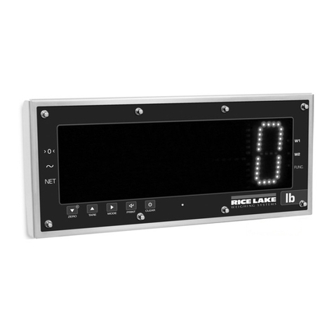
Rice Lake MSI-8000HD User manual

MSI-8000HD
RF Remote Display
Technical Manual
PN 159007 Rev CJuly 6, 2022

© Rice Lake Weighing Systems. All rights reserved.
Rice Lake Weighing Systems® is a registered trademark of
Rice Lake Weighing Systems.
All other brand or product names within this publication are trademarks or
registered trademarks of their respective companies.
All information contained within this publication is, to the best of our knowledge, complete and
accurate at the time of publication. Rice Lake Weighing Systems reserves the right to make
changes to the technology, features, specifications and design of the equipment without notice.
The most current version of this publication, software, firmware and all other product
updates can be found on our website:
www.ricelake.com

Revision History
© Rice Lake Weighing Systems ● All Rights Reserved i
Technical training seminars are available through Rice Lake Weighing Systems.
Course descriptions and dates can be viewed at www.ricelake.com/training
or obtained by calling 715-234-9171 and asking for the training department.
Revision History
This section tracks and describes the current and previous manual revisions for awareness of major updates and when the
updates took place.
Revision Date Description
C July 5, 2022 Revision history established after Rev C
Table i. Revision Letter History

Contents
MSI-8000HD RF Remote Display
ii Visit our website www.RiceLake.com
Rice Lake continually offers web-based video training on a growing selection
of product-related topics at no cost. Visit www.ricelake.com/webinars
1.0 Introduction . . . . . . . . . . . . . . . . . . . . . . . . . . . . . . . . . . . . . . . . . . . . . . . . . . . . . . . . . . . . . . . . . . . . . . . . . . . . 1
1.1 Features . . . . . . . . . . . . . . . . . . . . . . . . . . . . . . . . . . . . . . . . . . . . . . . . . . . . . . . . . . . . . . . . . . . . . . . . . . . . . . . . . . . . . . . . . . . 1
1.2 FCC Compliance. . . . . . . . . . . . . . . . . . . . . . . . . . . . . . . . . . . . . . . . . . . . . . . . . . . . . . . . . . . . . . . . . . . . . . . . . . . . . . . . . . . . . 1
1.3 Safety . . . . . . . . . . . . . . . . . . . . . . . . . . . . . . . . . . . . . . . . . . . . . . . . . . . . . . . . . . . . . . . . . . . . . . . . . . . . . . . . . . . . . . . . . . . . . 2
1.4 Front Panel Description. . . . . . . . . . . . . . . . . . . . . . . . . . . . . . . . . . . . . . . . . . . . . . . . . . . . . . . . . . . . . . . . . . . . . . . . . . . . . . . . 3
2.0 Installation . . . . . . . . . . . . . . . . . . . . . . . . . . . . . . . . . . . . . . . . . . . . . . . . . . . . . . . . . . . . . . . . . . . . . . . . . . . . . 4
2.1 Unpacking . . . . . . . . . . . . . . . . . . . . . . . . . . . . . . . . . . . . . . . . . . . . . . . . . . . . . . . . . . . . . . . . . . . . . . . . . . . . . . . . . . . . . . . . . . 4
2.2 Getting Started . . . . . . . . . . . . . . . . . . . . . . . . . . . . . . . . . . . . . . . . . . . . . . . . . . . . . . . . . . . . . . . . . . . . . . . . . . . . . . . . . . . . . . 4
2.3 Opening the Enclosure . . . . . . . . . . . . . . . . . . . . . . . . . . . . . . . . . . . . . . . . . . . . . . . . . . . . . . . . . . . . . . . . . . . . . . . . . . . . . . . . 4
2.4 Mounting the MSI-8000HD . . . . . . . . . . . . . . . . . . . . . . . . . . . . . . . . . . . . . . . . . . . . . . . . . . . . . . . . . . . . . . . . . . . . . . . . . . . . . 5
2.4.1 Mounting with Tilt Stand. . . . . . . . . . . . . . . . . . . . . . . . . . . . . . . . . . . . . . . . . . . . . . . . . . . . . . . . . . . . . . . . . . . . . . . . 5
2.4.2 Direct Mounting . . . . . . . . . . . . . . . . . . . . . . . . . . . . . . . . . . . . . . . . . . . . . . . . . . . . . . . . . . . . . . . . . . . . . . . . . . . . . . 5
3.0 Operation . . . . . . . . . . . . . . . . . . . . . . . . . . . . . . . . . . . . . . . . . . . . . . . . . . . . . . . . . . . . . . . . . . . . . . . . . . . . . . 6
3.1 Power . . . . . . . . . . . . . . . . . . . . . . . . . . . . . . . . . . . . . . . . . . . . . . . . . . . . . . . . . . . . . . . . . . . . . . . . . . . . . . . . . . . . . . . . . . . . . 6
3.2 Zero. . . . . . . . . . . . . . . . . . . . . . . . . . . . . . . . . . . . . . . . . . . . . . . . . . . . . . . . . . . . . . . . . . . . . . . . . . . . . . . . . . . . . . . . . . . . . . . 6
3.3 Tare. . . . . . . . . . . . . . . . . . . . . . . . . . . . . . . . . . . . . . . . . . . . . . . . . . . . . . . . . . . . . . . . . . . . . . . . . . . . . . . . . . . . . . . . . . . . . . . 6
3.3.1 View Tare . . . . . . . . . . . . . . . . . . . . . . . . . . . . . . . . . . . . . . . . . . . . . . . . . . . . . . . . . . . . . . . . . . . . . . . . . . . . . . . . . . . 6
3.3.2 Clear Tare . . . . . . . . . . . . . . . . . . . . . . . . . . . . . . . . . . . . . . . . . . . . . . . . . . . . . . . . . . . . . . . . . . . . . . . . . . . . . . . . . . 6
4.0 Setup. . . . . . . . . . . . . . . . . . . . . . . . . . . . . . . . . . . . . . . . . . . . . . . . . . . . . . . . . . . . . . . . . . . . . . . . . . . . . . . . . . 7
4.1 Setup Navigation. . . . . . . . . . . . . . . . . . . . . . . . . . . . . . . . . . . . . . . . . . . . . . . . . . . . . . . . . . . . . . . . . . . . . . . . . . . . . . . . . . . . . 7
4.2 Setup Menu. . . . . . . . . . . . . . . . . . . . . . . . . . . . . . . . . . . . . . . . . . . . . . . . . . . . . . . . . . . . . . . . . . . . . . . . . . . . . . . . . . . . . . . . . 8
4.3 Function Keys . . . . . . . . . . . . . . . . . . . . . . . . . . . . . . . . . . . . . . . . . . . . . . . . . . . . . . . . . . . . . . . . . . . . . . . . . . . . . . . . . . . . . . . 9
4.3.1 Test . . . . . . . . . . . . . . . . . . . . . . . . . . . . . . . . . . . . . . . . . . . . . . . . . . . . . . . . . . . . . . . . . . . . . . . . . . . . . . . . . . . . . . . 9
4.3.2 Total . . . . . . . . . . . . . . . . . . . . . . . . . . . . . . . . . . . . . . . . . . . . . . . . . . . . . . . . . . . . . . . . . . . . . . . . . . . . . . . . . . . . . . . 9
4.3.3 Net/Gross . . . . . . . . . . . . . . . . . . . . . . . . . . . . . . . . . . . . . . . . . . . . . . . . . . . . . . . . . . . . . . . . . . . . . . . . . . . . . . . . . . 10
4.3.4 Peak Hold. . . . . . . . . . . . . . . . . . . . . . . . . . . . . . . . . . . . . . . . . . . . . . . . . . . . . . . . . . . . . . . . . . . . . . . . . . . . . . . . . . 10
4.3.5 Units . . . . . . . . . . . . . . . . . . . . . . . . . . . . . . . . . . . . . . . . . . . . . . . . . . . . . . . . . . . . . . . . . . . . . . . . . . . . . . . . . . . . . . 10
4.3.6 Hi-Res . . . . . . . . . . . . . . . . . . . . . . . . . . . . . . . . . . . . . . . . . . . . . . . . . . . . . . . . . . . . . . . . . . . . . . . . . . . . . . . . . . . . 10
4.3.7 Print . . . . . . . . . . . . . . . . . . . . . . . . . . . . . . . . . . . . . . . . . . . . . . . . . . . . . . . . . . . . . . . . . . . . . . . . . . . . . . . . . . . . . . 10
4.3.8 Total Remote Devices . . . . . . . . . . . . . . . . . . . . . . . . . . . . . . . . . . . . . . . . . . . . . . . . . . . . . . . . . . . . . . . . . . . . . . . . 11
4.4 Auto-Off. . . . . . . . . . . . . . . . . . . . . . . . . . . . . . . . . . . . . . . . . . . . . . . . . . . . . . . . . . . . . . . . . . . . . . . . . . . . . . . . . . . . . . . . . . . 11
4.5 Setpoints . . . . . . . . . . . . . . . . . . . . . . . . . . . . . . . . . . . . . . . . . . . . . . . . . . . . . . . . . . . . . . . . . . . . . . . . . . . . . . . . . . . . . . . . . . 12
4.6 Output . . . . . . . . . . . . . . . . . . . . . . . . . . . . . . . . . . . . . . . . . . . . . . . . . . . . . . . . . . . . . . . . . . . . . . . . . . . . . . . . . . . . . . . . . . . . 13
4.7 Battery Life – Optional. . . . . . . . . . . . . . . . . . . . . . . . . . . . . . . . . . . . . . . . . . . . . . . . . . . . . . . . . . . . . . . . . . . . . . . . . . . . . . . . 13
4.8 Remote Scale Setup . . . . . . . . . . . . . . . . . . . . . . . . . . . . . . . . . . . . . . . . . . . . . . . . . . . . . . . . . . . . . . . . . . . . . . . . . . . . . . . . . 14
4.8.1 Filter Setup. . . . . . . . . . . . . . . . . . . . . . . . . . . . . . . . . . . . . . . . . . . . . . . . . . . . . . . . . . . . . . . . . . . . . . . . . . . . . . . . . 14
4.8.2 Total Mode . . . . . . . . . . . . . . . . . . . . . . . . . . . . . . . . . . . . . . . . . . . . . . . . . . . . . . . . . . . . . . . . . . . . . . . . . . . . . . . . . 14
4.8.3 Standard. . . . . . . . . . . . . . . . . . . . . . . . . . . . . . . . . . . . . . . . . . . . . . . . . . . . . . . . . . . . . . . . . . . . . . . . . . . . . . . . . . . 16
5.0 Calibration . . . . . . . . . . . . . . . . . . . . . . . . . . . . . . . . . . . . . . . . . . . . . . . . . . . . . . . . . . . . . . . . . . . . . . . . . . . . 17

Contents
© Rice Lake Weighing Systems ● All Rights Reserved iii
Technical training seminars are available through Rice Lake Weighing Systems.
Course descriptions and dates can be viewed at www.ricelake.com/training
or obtained by calling 715-234-9171 and asking for the training department.
5.1 Calibration Switch . . . . . . . . . . . . . . . . . . . . . . . . . . . . . . . . . . . . . . . . . . . . . . . . . . . . . . . . . . . . . . . . . . . . . . . . . . . . . . . . . . . 17
5.2 Initial Calibration . . . . . . . . . . . . . . . . . . . . . . . . . . . . . . . . . . . . . . . . . . . . . . . . . . . . . . . . . . . . . . . . . . . . . . . . . . . . . . . . . . . . 18
5.2.1 Routine Calibration. . . . . . . . . . . . . . . . . . . . . . . . . . . . . . . . . . . . . . . . . . . . . . . . . . . . . . . . . . . . . . . . . . . . . . . . . . . 19
5.2.2 C-Cal Calibration . . . . . . . . . . . . . . . . . . . . . . . . . . . . . . . . . . . . . . . . . . . . . . . . . . . . . . . . . . . . . . . . . . . . . . . . . . . . 20
5.3 Setup. . . . . . . . . . . . . . . . . . . . . . . . . . . . . . . . . . . . . . . . . . . . . . . . . . . . . . . . . . . . . . . . . . . . . . . . . . . . . . . . . . . . . . . . . . . . . 21
5.4 Reset the Load Cell Calibration . . . . . . . . . . . . . . . . . . . . . . . . . . . . . . . . . . . . . . . . . . . . . . . . . . . . . . . . . . . . . . . . . . . . . . . . 22
5.5 Auto Zero Maintenance (AZM) . . . . . . . . . . . . . . . . . . . . . . . . . . . . . . . . . . . . . . . . . . . . . . . . . . . . . . . . . . . . . . . . . . . . . . . . . 23
5.6 Zero Power Up (0.P-UP) . . . . . . . . . . . . . . . . . . . . . . . . . . . . . . . . . . . . . . . . . . . . . . . . . . . . . . . . . . . . . . . . . . . . . . . . . . . . . . 23
6.0 Communications . . . . . . . . . . . . . . . . . . . . . . . . . . . . . . . . . . . . . . . . . . . . . . . . . . . . . . . . . . . . . . . . . . . . . . . 24
6.1 Communications Setup . . . . . . . . . . . . . . . . . . . . . . . . . . . . . . . . . . . . . . . . . . . . . . . . . . . . . . . . . . . . . . . . . . . . . . . . . . . . . . . 24
6.2 Communications Menu . . . . . . . . . . . . . . . . . . . . . . . . . . . . . . . . . . . . . . . . . . . . . . . . . . . . . . . . . . . . . . . . . . . . . . . . . . . . . . . 24
6.3 Printer Setup . . . . . . . . . . . . . . . . . . . . . . . . . . . . . . . . . . . . . . . . . . . . . . . . . . . . . . . . . . . . . . . . . . . . . . . . . . . . . . . . . . . . . . . 25
6.3.1 Control Modes . . . . . . . . . . . . . . . . . . . . . . . . . . . . . . . . . . . . . . . . . . . . . . . . . . . . . . . . . . . . . . . . . . . . . . . . . . . . . . 25
6.3.2 Standard Print Strings . . . . . . . . . . . . . . . . . . . . . . . . . . . . . . . . . . . . . . . . . . . . . . . . . . . . . . . . . . . . . . . . . . . . . . . . 26
6.3.3 Printer Output Setup . . . . . . . . . . . . . . . . . . . . . . . . . . . . . . . . . . . . . . . . . . . . . . . . . . . . . . . . . . . . . . . . . . . . . . . . . 27
6.4 Radio Setup . . . . . . . . . . . . . . . . . . . . . . . . . . . . . . . . . . . . . . . . . . . . . . . . . . . . . . . . . . . . . . . . . . . . . . . . . . . . . . . . . . . . . . . 28
6.5 Setup Multiple Sensor Network. . . . . . . . . . . . . . . . . . . . . . . . . . . . . . . . . . . . . . . . . . . . . . . . . . . . . . . . . . . . . . . . . . . . . . . . . 30
6.5.1 Set the Total Number of Load Cells . . . . . . . . . . . . . . . . . . . . . . . . . . . . . . . . . . . . . . . . . . . . . . . . . . . . . . . . . . . . . . 31
6.5.2 Scan Weight Inputs . . . . . . . . . . . . . . . . . . . . . . . . . . . . . . . . . . . . . . . . . . . . . . . . . . . . . . . . . . . . . . . . . . . . . . . . . . 31
6.5.3 Load Totaling Settings . . . . . . . . . . . . . . . . . . . . . . . . . . . . . . . . . . . . . . . . . . . . . . . . . . . . . . . . . . . . . . . . . . . . . . . . 31
6.6 ScanList ID . . . . . . . . . . . . . . . . . . . . . . . . . . . . . . . . . . . . . . . . . . . . . . . . . . . . . . . . . . . . . . . . . . . . . . . . . . . . . . . . . . . . . . . . 32
6.7 Zero and Tare in Multiple Load Cell Systems . . . . . . . . . . . . . . . . . . . . . . . . . . . . . . . . . . . . . . . . . . . . . . . . . . . . . . . . . . . . . . 32
6.8 Communications Port Hardware . . . . . . . . . . . . . . . . . . . . . . . . . . . . . . . . . . . . . . . . . . . . . . . . . . . . . . . . . . . . . . . . . . . . . . . . 33
6.9 Relays . . . . . . . . . . . . . . . . . . . . . . . . . . . . . . . . . . . . . . . . . . . . . . . . . . . . . . . . . . . . . . . . . . . . . . . . . . . . . . . . . . . . . . . . . . . . 34
6.9.1 Relay Options. . . . . . . . . . . . . . . . . . . . . . . . . . . . . . . . . . . . . . . . . . . . . . . . . . . . . . . . . . . . . . . . . . . . . . . . . . . . . . . 35
6.9.2 Extended Relay Kit – Optional . . . . . . . . . . . . . . . . . . . . . . . . . . . . . . . . . . . . . . . . . . . . . . . . . . . . . . . . . . . . . . . . . . 36
6.10 Radio Compliance. . . . . . . . . . . . . . . . . . . . . . . . . . . . . . . . . . . . . . . . . . . . . . . . . . . . . . . . . . . . . . . . . . . . . . . . . . . . . . . . . . . 36
6.10.1 802.15.4 (XBee 3 and XBee 3-PRO) . . . . . . . . . . . . . . . . . . . . . . . . . . . . . . . . . . . . . . . . . . . . . . . . . . . . . . . . . . . . . 36
6.10.2 802.15.4 (XBee 2SC) . . . . . . . . . . . . . . . . . . . . . . . . . . . . . . . . . . . . . . . . . . . . . . . . . . . . . . . . . . . . . . . . . . . . . . . . . 37
6.10.3 Wi-Fi. . . . . . . . . . . . . . . . . . . . . . . . . . . . . . . . . . . . . . . . . . . . . . . . . . . . . . . . . . . . . . . . . . . . . . . . . . . . . . . . . . . . . . 37
6.10.4 Bluetooth . . . . . . . . . . . . . . . . . . . . . . . . . . . . . . . . . . . . . . . . . . . . . . . . . . . . . . . . . . . . . . . . . . . . . . . . . . . . . . . . . . 37
6.10.5 FHSS (Frequency Hopper Spread Spectrum) . . . . . . . . . . . . . . . . . . . . . . . . . . . . . . . . . . . . . . . . . . . . . . . . . . . . . . 37
6.11 Antenna Options . . . . . . . . . . . . . . . . . . . . . . . . . . . . . . . . . . . . . . . . . . . . . . . . . . . . . . . . . . . . . . . . . . . . . . . . . . . . . . . . . . . . 38
6.11.1 Available Antennas . . . . . . . . . . . . . . . . . . . . . . . . . . . . . . . . . . . . . . . . . . . . . . . . . . . . . . . . . . . . . . . . . . . . . . . . . . 39
7.0 Troubleshooting and Maintenance . . . . . . . . . . . . . . . . . . . . . . . . . . . . . . . . . . . . . . . . . . . . . . . . . . . . . . . . 40
7.1 Troubleshooting . . . . . . . . . . . . . . . . . . . . . . . . . . . . . . . . . . . . . . . . . . . . . . . . . . . . . . . . . . . . . . . . . . . . . . . . . . . . . . . . . . . . 40
7.2 Error Codes. . . . . . . . . . . . . . . . . . . . . . . . . . . . . . . . . . . . . . . . . . . . . . . . . . . . . . . . . . . . . . . . . . . . . . . . . . . . . . . . . . . . . . . . 41
7.3 Service Counters. . . . . . . . . . . . . . . . . . . . . . . . . . . . . . . . . . . . . . . . . . . . . . . . . . . . . . . . . . . . . . . . . . . . . . . . . . . . . . . . . . . . 41
7.3.1 Access the Service Counters . . . . . . . . . . . . . . . . . . . . . . . . . . . . . . . . . . . . . . . . . . . . . . . . . . . . . . . . . . . . . . . . . . . 41
7.4 Mechanical Dimensions . . . . . . . . . . . . . . . . . . . . . . . . . . . . . . . . . . . . . . . . . . . . . . . . . . . . . . . . . . . . . . . . . . . . . . . . . . . . . . 42
7.5 Firmware Update. . . . . . . . . . . . . . . . . . . . . . . . . . . . . . . . . . . . . . . . . . . . . . . . . . . . . . . . . . . . . . . . . . . . . . . . . . . . . . . . . . . . 43
7.6 Factory Reset . . . . . . . . . . . . . . . . . . . . . . . . . . . . . . . . . . . . . . . . . . . . . . . . . . . . . . . . . . . . . . . . . . . . . . . . . . . . . . . . . . . . . . 44
8.0 Specifications . . . . . . . . . . . . . . . . . . . . . . . . . . . . . . . . . . . . . . . . . . . . . . . . . . . . . . . . . . . . . . . . . . . . . . . . . 45

Introduction
© Rice Lake Weighing Systems ● All Rights Reserved 1
1.0 Introduction
The MSI-8000HD RF Remote Display makes wireless control easy with the ability to operate weighing systems from a distance.
The wireless remote display can be used for viewing MSI ScaleCore-based crane scales and dynamometers, including any RF
compatible MSI-3460 Challenger 3, MSI-4260 Port-A-Weigh or MSI-7300 Dyna-Link 2. It has an RF effective range of 100 ft
(line of sight) and operates on a license-free 2.4 GHz frequency.
It is fully sealed for outdoor use in most ambient conditions and enhances the safety and usability of Rice Lake’s Dyna-Link and
crane scale systems. Installed optional relays optimize work-flow and process control.
This manual is intended for use by qualified technicians responsible for setting up and operating the MSI-8000HD.
Manuals and additional resources are available from Rice Lake Weighing Systems at www.ricelake.com/manuals
Warranty information can be found on the website at www.ricelake.com/warranties
1.1 Features
• Meets or exceeds U.S./international safety and environmental standards
• No license required; Meets U.S./International RF transmission laws
• The display enclosure is IP66 for outdoor use
• The enclosure is built with rugged construction throughout with shock cushioning on the corners
• Six, 1'' (24 mm), LCD digits for clear weight readings
• Selectable units for kg/lb/tons (US Short)/metric tons/kilo-newtons
• Automatic or manual weight totalization for loading operations
• Eight setpoints can be set for in-range load/weight value for operator alerts or process control
• ScaleCore technology provides quick and easy firmware updates and calibration/setup backup
• Optional hard-wired link for applications where RF is not allowed
1.2 FCC Compliance
United States
This equipment has been tested and found to comply with the limits for a Class A digital device, pursuant to Part 15 of the FCC
Rules. These limits are designed to provide reasonable protection against harmful interference when the equipment is operated
in a commercial environment. This equipment generates, uses, and can radiate radio frequency energy and, if not installed and
used in accordance with the instruction manual, may cause harmful interference to radio communications. Operation of this
equipment in a residential area is likely to cause harmful interference in which case the user will be required to correct the
interference at his own expense.
Canada
This digital apparatus does not exceed the Class A limits for radio noise emissions from digital apparatus set out in the Radio
Interference Regulations of the Canadian Department of Communications.
Le présent appareil numérique n'émet pas de bruits radioélectriques dépassant les limites applicables aux appareils
numériques de la Class A prescites dans le Règlement sur le brouillage radioélectrique edicté par le ministère des
Communications du Canada.

MSI-8000HD RF Remote Display
2 Visit our website www.ricelake.com
1.3 Safety
Safety Definitions:
DANGER: Indicates an imminently hazardous situation that, if not avoided, will result in death or serious injury. Includes
hazards that are exposed when guards are removed.
WARNING: Indicates a potentially hazardous situation that, if not avoided, could result in serious injury or death. Includes
hazards that are exposed when guards are removed.
CAUTION: Indicates a potentially hazardous situation that, if not avoided, could result in minor or moderate injury.
IMPORTANT: Indicates information about procedures that, if not observed, could result in damage to equipment or
corruption to and loss of data.
General Safety
Do not operate or work on this equipment unless this manual has been read and all instructions are understood.
Failure to follow the instructions or heed the warnings could result in injury or death. Contact any Rice Lake
Weighing Systems dealer for replacement manuals.
WARNING
Failure to heed could result in serious injury or death.
Do not allow minors (children) or inexperienced persons to operate this unit.
Do not stand near a load being lifted as it is a potential falling hazard. Keep a safe distance.
Do not use for purposes other then weight taking or dynamic load monitoring.
Do not use any load bearing component that is worn beyond five percent of the original dimension.
Do not use any associated lifting product if any of the load bearing components are cracked, deformed or show signs of fatigue.
Do not exceed the rated load limit of the associated scale/dynamometer unit, rigging element or the lifting structure.
Do not allow multi-point contact with the hook, shackle or lifting eye of the associated scale/dynamometer unit.
Do not allow high torque on the scale/dynamometer unless it is specifically designed for high torque.
Do not make alterations or modifications to the unit or associated load bearing devices; any alterations void the warranty.
Do not remove or obscure warning labels.
There are no user serviceable parts within the unit. Any repairs must be performed by qualified service personnel only.
Close proximity to audible alarm for sustained periods of time could be hazardous. Hearing protection may be required.
Do not use solvents or agressive substances to clean the MSI-800HD.
Do not submerge.

Introduction
© Rice Lake Weighing Systems ● All Rights Reserved 3
1.4 Front Panel Description
The MSI-8000HD front panel, keys and annunciators, are described in Table 1-1 on page 3.
Figure 1-1. MSI-8000HD Front Panel
Key/Annunciator Functions
Item No. Key Description
1Function 1 Programmable to user selectable functions (Section 4.3 on page 9); Default is Off;
Functions as the Enter/Select key when in the setup menus
2Function 2 Programmable to user selectable functions (Section 4.3 on page 9); Default is Off;
Functions as the Scroll key in the setup menus
3 Function 3 Pre-programmed to Print and cannot be changed
4 Center of Zero Indicates that the scale/Dyna-Link is within 1/4 d of zero
5Standstill Indicates that the load has settled within the motion window (usually ± 1 d);
When this is turned off, the scale/Dyna-Link will not zero, tare or totalize
6LED Functions Indicates the current displayed function
Example: If F1 blinks, the peak hold reading is captured. If F2 blinks, the Display and Function Test reading is captured.
7 Total Indicates the RF linked device is displaying the total accumulated weight; Displays only momentarily
Peak Indicates the RF linked device is in the peak hold mode
Net Indicates the RF linked device is in Net load mode; A tare weight is subtracted from the gross load
Metric Ton In conjunction with the Ton annunciator, indicates the RF linked device is displaying metric tons
Ton Illuminated, indicates the RF Linked Device is displaying in U.S. Short Tons (1 ton = 2000 lb);
When illuminated with M the RF Linked Device is displaying in metric tons (1 metric ton = 1000 kg)
Kilonewtons Indicates load display is in kilonewtons
Kilograms Indicates load display is in kilograms
Pound Indicates load display is in pounds
8 Setpoints User programmable setpoints for overload warnings; Setpoints 1 and 2 are red high brightness LEDs
9Multiple Sensors Number lit indicates the sensor being displayed; If more than one number is lit, sensors are being summed
Example: If both numbers 1 and 2 are lit, then the weight displayed equals the sum of sensor 1 and sensor 2.
10 Display Digits Include six 1.22'' (31 mm) sunlight visible LCD’s
11 Power Powers the unit on and off; In setup mode, it returns the display to the weigh mode without storing changes
12 Zero Zeros the residual load on a scale/Dyna-Link 2; In setup mode, it stores changes and returns to the prior level
13 Tare Removes current load value and puts the system into Net weight mode
14 Low Battery Indicates about 10% of battery life remains; Symbol flashes when automatic shutdown is eminent
Table 1-1. Keypad/Annunciator Functions
MSI-8000
Measurement Systems
International
TM
FUNCTION
PRINT
ZERO
POWER
TARE
SETPOINTS12
F3
F2
F1
12
Class III/IIIL nmax =10000
1
2
3
6 8
479
10
11
12
13
5
14

MSI-8000HD RF Remote Display
4 Visit our website www.ricelake.com
2.0 Installation
This section provides an overview of MSI-8000HD RF Remote Display installation instructions.
2.1 Unpacking
When unpacking the MSI-8000HD, ensure that all parts are accounted for and check for any visible damage. If any parts were
damaged in shipment, notify Rice Lake Weighing Systems and the shipper immediately. If the MSI-8000HD must be returned, it
must be properly packed with sufficient packing materials. If possible, retain the original carton when shipping the unit back.
2.2 Getting Started
The MSI-8000HD is often shipped pre-configured with a compatible sensor unit such as an Dyna-Link 2 or one of the MSI crane
scales. If the MSI-8000HD is purchased separately, or is to be used with a different system, the RF transceivers will have to be
paired. Follow the RF Setup Procedure in Section 6.4 on page 28.
Once the RF setup is complete for the MSI-8000HD, the system will automatically connect with a scale/Dyna-Link. It is
recommended to do a site survey to identify operating range and usability of the RF Link. Position the scale/Dyna-Link at an
average operational height, and try the link at various positions and distances. The range may vary by the rotation of the scale/
Dyna-Link, as well as the site and installation variables.
Battery Charging (Optional)
For units with an optional battery, fully charge the battery by plugging the charger into the charge port. Depending on the
discharge level of the battery this can take up to six hours.
Figure 2-1. Battery Charger
2.3 Opening the Enclosure
The indicator enclosure must be opened to connect the scale load cell cable and other interface connections.
WARNING: Before opening the unit, ensure the power cord is disconnected from the power outlet.
1. Disconnect the power to the indicator.
2. Place the indicator face down on an anti-static work mat.
3. Remove the screws that secure the backplate to the enclosure.
4. Lift the backplate away to access the boards and set it aside.

Installation
© Rice Lake Weighing Systems ● All Rights Reserved 5
2.4 Mounting the MSI-8000HD
The MSI-8000HD can be placed on a table, counter or table using the tilt stand. The tilt stand is equipped with four rubber
bumper to keep it from sliding while using the MSI-8000HD.
2.4.1 Mounting with Tilt Stand
A tilt stand is shipped with the MSI-8000HD for mounting. It can be mounted on a desk, counter or table. It can also be mounted
to a wall or panel and the MSI-8000HD can be rotated for easy viewing.
Figure 2-2. Tilt Stand – Bottom Dimensions
To secure to one of the options above:
1. Using the tilt stand, mark holes as needed.
2. Drill the holes for the hardware being used.
3. Secure the tilt stand to the surface. If mounting to a wall or panel, ensure it is mounted horizontally.
4. Install the MSI-8000HD into the tilt stand at an angle that will allow easy viewing.
2.4.2 Direct Mounting
The MSI-8000HD can be mounted directly to a wall or panel using the four holes in the corners of the unit.
1. Hold the remote display against the wall or panel where it is to be mounted.
2. Mark the hole location. This can also be done by measuring according to the dimensions in Figure 2-3.
3. Drill the holes as needed.
4. Align the unit with the holes and secure with the appropriate hardware.
Figure 2-3. Mounting Hole Dimensions
0.38
0.88
0.56 TYP
2.12
0.57
0.57
2.753.19 3.19
0.56
0.38
0.38
0.56
Mounting Holes

MSI-8000HD RF Remote Display
6 Visit our website www.ricelake.com
3.0 Operation
This section provides an overview of MSI-8000HD RF Remote Display operation instructions.
NOTE: Ensure the recommended battery or power supply is secured prior to device operation (Section 2.0 on page 4).
3.1 Power
Power the indicator On/Off by pressing .
3.2 Zero
Press to take out small deviations in zero when the scale is unloaded. For zeroing (taring) package or pallet weights,
see Section 3.3. The zero key can be used in GROSS or NET mode.
NOTE: The backup memory in the unit stores the zero reading and retains it even if the power fails.
Zeroing while in NET mode will zero the GROSS weight causing the display to show a negative tare value.
The scale must be stable within the stable window.
The unit will only zero if is on and there has been no activity for two seconds.
The scale will accept a zero setting over the full range of the scale (NTEP and other Legal for Trade models may have a
limited zero range).
Zero settings above 4% of full scale will subtract from the overall capacity of the unit.
Example: If 100 lb on a 1,000 lb scale is zeroed, the overall capacity of the scale will reduce to 900 lb, plus the allowed over-
range amount.
3.3 Tare
Tare is used to zero out a known weight, such as a packing container or pallet, and display a NET weight. The TARE function is
defined as a Tare-In or Tare-Out operation. To tare the scale:
1. Hang the empty container from the scale.
2. Press to enter a tare value. The MSI-3460C stores the current weight as a tare value and subtracts the value
of the container from the GROSS weight. displays and the weight mode changes to NET.
3. Add the product to the packing container. The NET weight is displayed.
3.3.1 View Tare
To view the GROSS weight without clearing the tare value:
1. Program to the NET/GROSS function (Section 4.3 on page 9).
2. Press to toggle between net and GROSS values. This will only work if a tare value has been established.
NOTE: The backup memory in the MSI-8000HD stores the Tare reading and can restore it even if power fails.
Only positive GROSS weight readings can be tared. The STABLE annunciator must be on, indicating weight reading is
stable. Setting or changing the tare has no effect on the GROSS zero setting. Taring will reduce the apparent over range of
the scale. The RF Remote Control has NET/GROSS permanently available.
Example: Taring a 100 lb container on a 1,000 lb scale, the scale will overload at a NET weight of 900 lb (1,000-
100) plus any additional allowed overload (usually 4% or 9d).
3.3.2 Clear Tare
To clear a saved tare value, press . The GROSS weight displays.
POWER
ZERO
TARE
F1
F1
TARE

Setup
© Rice Lake Weighing Systems ● All Rights Reserved 7
4.0 Setup
This section provides an overview of MSI-8000HD RF Remote Display setup instructions.
4.1 Setup Navigation
To navigate the menus during setup, follow the information below:
• Press to enter or select a parameter
• Press to scroll through the parameters
• To enter a decimal point, press while the digit is blinking
• Press to save and go back one level or to weigh mode; displays briefly
• If a wrong value is entered, press to step back one digit and press to change the digit
• Press to exit without saving changes
F1
F2
POWER
ZERO
ZERO
F2
POWER

MSI-8000HD RF Remote Display
8 Visit our website www.ricelake.com
4.2 Setup Menu
To enter the setup menu on the MSI 8000HD RF Remote display receiver, press and keys at the same time.
The MSI-8000HD RF Remote Display is capable of performing setup function remotely on the RF transmitter that it is receiving
information from. To enter the setup menu of the connected scale or weight indicator, press and keys at the
same time
Parameters Choices Description
–Function key 1 – Configurable to listed parameters (Section 4.3 on page 9); Default
Function key 2 – Configurable to listed parameters (Section 4.3 on page 9); Default
No function is assigned; The F-Key is disabled
Test – Runs an LCD test (Section 4.3.1 on page 9)
Total – Accumulates multiple weighments (Section 4.3.2 on page 9)
View total – Activates the total weight display followed by the number of samples
(Section 4.3.2 on page 9)
Net/Gross – Toggles between Net and Gross modes (Section 4.3.3 on page 10)
Peak Hold – Automatically updates the display when a higher peak weight reading is estab-
lished (Section 4.3.4 on page 10)
2 Units – Switches the force units between lb and kg or tons and metric tons, depending on
unit currently selected (Section 4.3.5 on page 10).
5 Units – Scrolls through all available units: lb, kg, Tons (US Short), metric tons and kilonew-
tons (Section 4.3.5 on page 10)
Hi Res – The unit is more sensitive to motion and movement resulting in a less stable display
(Section 4.3.6 on page 10)
Print – Outputs a configured text string to the RS-232 port on the base of the Dyna-Link
(Section 4.3.7 on page 10)
Tare – Not used, MSI-8000HD has a dedicated tare key
Scan – Displays RF connected channels in order
Total Remote Devices – Displays the summed weight of RF connected sensors
(Section 4.3.8 on page 11)
Off
15
30
45
60
Auto Off – Prolongs the battery life of the scale by turning power off after the set time (in min-
utes) that the scale is not in use (Section 4.4 on page 11)
GrEat Greater Than – Setpoint will trigger when the tension exceeds the value
LESS Less Than – Setpoint will trigger when the tension is less than the value
OFF Off - The setpoint parameter is disabled
– Relay Output – Dependant on the application being used
Latch Latch – If power is lost, the relay retains it’s settings
Coil Coil – Needs power to remain position
Stand
LonG Battery Life – Sets the options for standard or extended battery life (Section 4.7 on page 13)
indUs
Hb-44
r-76
1Unit
Standards – Sets the industry standard to be used
Table 4-1. Setup Menu Parameter Descriptions
F2
POWER
PRINT
F3
POWER

Setup
© Rice Lake Weighing Systems ● All Rights Reserved 9
4.3 Function Keys
There are two programmable function keys on the MSI-8000HD, F1 and F2.
• Function key setup is independent of the connected scale/Dyna-Link function keys
• and are standard on the MSI-8000HD and do not need to be programmed
• If a function key does not work, the connected RF transmitter may not be set up to support the key
Example: If the Function key is set for TOTAL, then TOTAL mode setup in the Setup Menu must also be set up for
the target scale.
To set a function key use the following steps:
1. Press and at the same time, will display.
2. Press to scroll to the function key to be programmed.
3. Press . The currently saved parameter will display.
4. Press to scroll through the choices.
5. Press to select the desired choice.
6. Press to save and exit.
4.3.1 Test
The test feature only tests the MSI-8000HD. Set an F-key to TEST.
To run a test, press Fx-TEST, the following items scroll across the display.
• Light all LCD segments and the LEDs
• followed by the version number
• followed by the battery level in volts
• followed by counting from 00000–99999
• followed by the weighing standard
The test can be single stepped by:
1. Press Fx-TEST, immediately press to stop the auto scroll.
2. Use to scroll through the steps and to view the step value.
3. Press to abort the test at any time.
Internal tests are also performed, if any test fails, an error code is displayed. See Section 7.2 on page 41 for a description of all
error codes.
4.3.2 Total
1. Ensure the total mode has been programmed in the setup menu. If this has not been setup the F-Key assigned to
Total will not work.
2. Program an F-key to Total (Section 4.3).
3. Press Fx-Total to perform the total function that was set in Section 4.8.2 on page 14.
TARE
PRINT
F3
POWER
F2
F2
F1
F2
F1
ZERO
F2
F2
F1
ZERO

MSI-8000HD RF Remote Display
10 Visit our website www.ricelake.com
4.3.3 Net/Gross
Program an F-key to NetGross (Section 4.3 on page 9).
Press Fx-NetGross to toggle between gross and net (gross minus tare). Fx-NetGross only functions if a tare has been
established.
The operator can switch back to gross from net without clearing the tare value. Only clearing or setting a new tare will change
the tare value held before switching into Gross Mode.
4.3.4 Peak Hold
Peak hold uses a high speed mode of the A/D converter allowing it to capture transient loads at a far higher rate than typical
Dynameters.
• Peak Hold is cleared and enabled by pressing Fx-P-HLd
• When a new peak is detected, the Fx LED will flash three times
• The accuracy of the system in peak hold is slightly reduced to 0.2% of Capacity + 5 d
• The filter setting is turned off while in peak hold mode to ensure the fastest acquisition rate
Example: The Peak Hold function is useful in Dynamic and Fall tests. Common tests include Overall Breaking
Strain (OB€), Breaking Force, and Cycled Breaking Strain.
Capture Peak Force:
1. Program an F-key to P-HLd (Section 4.3 on page 9).
2. Prepare the stand test and test sample.
3. Press .
4. Press Fx-P-HLd, confirm that Pk is lit on the display.
NOTE: A small jump in the reading occurs depending on the stability of the test device.
5. Apply the test weight. The Fx LED will blink three times when a new peak ID is detected
6. Remove the weight and the peak value is recorded.
7. To run a new test, press Fx-P-HLd to clear the peak value. Repeat Step 3–Step 6.
4.3.5 Units
Program an F-key to Unit (Section 4.3 on page 9).
Press Fx-Unit to set the units parameter to units required for display.
4.3.6 Hi-Res
When set to on, the filter is automatically set to the Hi-1 setting (if Hi-2 is already set, then the filter is not changed). This will
have a small effect on settling time. When set to off, the filter setting resets to the previous filter setting.
Program an F-key to HiRes (Section 4.3 on page 9).
Pressing Fx-HiRes places the display into a temporary high resolution mode. This mode continues until Fx-HiRes is pressed
again, or power is cycled. In the Hi-Res mode the appropriate Fx LED blinks continuously at a slow rate.
NOTE: Hi-Res mode does not increase the accuracy, but allows for smaller weight incrementation to display.
Use or to zero out any initial error.
Hi-Res mode is not available when the weighing standard is set to a legal-for-trade standard such as HB-44 or R76
4.3.7 Print
The Print function is set to F-3 key, so there is no need to program F1 or F2 to Print. Then pushing F1 or F2 on the scale will
cause the Comm Port on the Remote to output the selected data string.
If an F-Key is programmed as Print and the Print Setup is configured as continuous, then the F3-Print key is used for Start Print/
Stop Print.
ZERO
TARE
ZERO

Setup
© Rice Lake Weighing Systems ● All Rights Reserved 11
4.3.8 Total Remote Devices
Sensor summing must be enabled in the communications setup menu. If the Pairs or Both modes are enabled in the
communications setup menu, then pressing Fx-ttl.rd will scroll through the available combinations.
NOTE: It is common to program F1 for SCAN and F2 for ttl.rd (Total Remote Devices) to allow quick switching between
individual channel displays (with Scan) or the summed weight (with ttL.rd).
4.4 Auto-Off
The Auto-Off feature prolongs the battery life by powering off the unit when not in use. When a button is pressed or the
detected load is in motion exceeding 10 d, the time limit is reset.
When disabled, the unit will only turn off by pressing , or the battery dies.
To set the Auto-Off function:
1. Press and hold and . displays.
2. Press to scroll to .
3. Press . The current auto off time displays.
4. Press to scroll through the available times.
5. Press when the desired time is displayed. displays.
6. Press to exit setup and store the settings.
POWER
F1
POWER
F2
F1
F2
F1
ZERO

MSI-8000HD RF Remote Display
12 Visit our website www.ricelake.com
4.5 Setpoints
The MSI-8000HD supports eight setpoints. Common uses of setpoints are for warnings or process control. It comes standard
with two LED outputs for triggered setpoints.The triggering of setpoints 1 and 2 are indicated on the two setpoint relays. All
eight setpoints can be used to trigger relays if the MSI-8000HD is ordered with relays.
The MSI-8000HD has an audible output option that is triggered by Setpoint 1. Contact Rice Lake Weighing Systems for other
setpoint output options.
To set the setpoint:
1. Press and hold and . displays.
2. Press to scroll to the desired setpoint ().
3. Press . The current setpoint mode is displayed.
4. Press to scroll to the setpoint mode desired.
5. Press . The current setpoint weight type is displayed.
6. Press to scroll to the desired weight type.
7. Press . The desired weight type continues to display.
8. Press . displays.
9. Press to toggle between and .
10. With the desired setting displayed, press . The current weight type value is displayed.
11. Press to scroll the numbers and to enter each digit.
12. When the correct value is displayed, press . The next setup menu item is displays.
NOTE: To enter a decimal point, press while the digit is blinking. To correct a digit, press to step back.
13. Press to exit setup and store the settings.
Setpoint Description
Setpoint Mode
Off Setpoint is not activated
Indicates the setpoint will trigger when the weight exceeds a set value
Indicates the setpoint will trigger when the weight is less than a set value
Setpoint Weight Type
responds to net or gross weight
responds to gross weight regardless of the display
responds to the totaled weight
responds to the total count (number of samples)
LFcnt responds to the number of times the weight has exceeded 25% of capacity
Table 4-2. Available Setpoint Settings
F2
POWER
F2
F1
F2
F1
F2
F1
F1
F2
F1
F2
F1
F1
POWER
ZERO
ZERO

Setup
© Rice Lake Weighing Systems ● All Rights Reserved 13
4.6 Output
Relay output allows the selection of Latch or Coil relays.
• Latch relays retain position even if the power fails
• Coil relays reset when power fails
IMPORTANT: In the event of a power failure, the Latch relay uses continuous battery power and will deplete the battery
more quickly than the coil relay.
1. Press and hold and . displays.
2. Press to scroll to the .
3. Press . The current setting is displayed.
4. Press to toggle between and .
NOTE: The display brightness changes when each setting is displayed.
5. Press when the desired setting is displayed. displays.
6. Press to exit setup and store the settings.
4.7 Battery Life – Optional
Select either Standard () or Long ().
In Long battery life mode, the system is placed into a sleep state for several seconds at a time if there is no change in tension.
This disables the display in order to reduce power consumption and increase battery life. After several seconds, the
MSI-8000HD will wake up to check for any changes in tension. If there is a change in tension, the unit will stay awake. The unit
will also stay awake if it is in configuration mode.
Although long battery life mode can significantly increase battery life, performance is better in Standard battery life mode.
1. Press and simultaneously. displays.
2. Press to scroll to .
3. Press . The currently saved battery life displays.
4. Press to toggle between the choices.
5. With choice displayed, press to select. displays.
6. Press to save and exit to weighing mode.
F1
POWER
F2
F1
F2
F1
ZERO
F2
POWER
F2
F1
F2
F1
ZERO

MSI-8000HD RF Remote Display
14 Visit our website www.ricelake.com
4.8 Remote Scale Setup
The MSI-8000HD RF Remote Display can be used to operate several MSI crane scales (MSI-4260, MSI-3460 and MSI-7300).
Some functions can also be set using the MSI-8000HD. The information in this section pertains to the setup of the scale being
used with the remote.
4.8.1 Filter Setup
The filter settings are used to stabilize the weight in an unstable condition. Increasing the filter will improve the stability, however
settling times will be longer. The MSI-8000HD employs algorithms that speed up large weight changes while still controlling
vibration even with high filter settings.
Use the following steps to set up filtering.
1. Press and simultaneously. displays.
2. Press to scroll to .
3. Press . The currently saved total mode displays.
4. Press to scroll through the choices.
5. With choice displayed, press to select. displays.
6. Press to save and exit to weighing mode.
4.8.2 Total Mode
For the accumulation of multiple weighments, the Total function uses the displayed load, so gross and net readings can be
added into the same total.
There are four modes of totalizing, a manual and three auto modes.
All modes require that the weight on the scale return below 0.5% (relative to full scale) of Gross Zero or Net Zero before the
next weighment can be added. Applied weight must be ≥1% of full scale above Gross Zero or Net Zero before it can be
totaled.
Parameters Choices Description
Weight Filter – allows the scale to adjust to situations where there may be movement
See Section 4.8.1 on page 14
Hi-2 – MSI-7300 only
Total Accumulation - sets the choice for weight accumulation for a single scale (Section 4.3.2 on page 9);
When set to off, it’s disabled
Total On - Is a manual choice for accumulation (Section 4.3.2 on page 9)
Auto Total - Choices for setting automatic accumulations
Greater Than – Setpoint triggers when the tension exceeds the value (Section 4.5 on page 12)
Less Than – Setpoint triggers when the tension is less than the value (Section 4.5 on page 12)
Off - The setpoint parameter is disabled (Section 4.5 on page 12)
Battery Life –Sets the options for standard or extended battery life;
See Section 4.7 on page 13
Table 4-3. Settings for the Scale using the Remote
PRINT
F3
ZERO
F2
F1
F2
F1
ZERO
Other manuals for MSI-8000HD
1
Table of contents
Other Rice Lake Monitor manuals

Rice Lake
Rice Lake SURVIVOR IQ F Series User manual

Rice Lake
Rice Lake MSI-8000 User manual

Rice Lake
Rice Lake LaserLight3 User manual

Rice Lake
Rice Lake LaserLight3 User manual

Rice Lake
Rice Lake CLS-680 User manual

Rice Lake
Rice Lake 1280 Enterprise Series Installation manual

Rice Lake
Rice Lake LaserLight User manual

Rice Lake
Rice Lake LaserLight3 User manual

Rice Lake
Rice Lake IQ plus 710 User manual

Rice Lake
Rice Lake LaserLight2 ConnexLink 167091 User manual