Rice Lake RL-42TT User manual

108223
RL-42TT
Thermal Printer
Operation Manual
108223


i
Contents
About This Manual ................................................................................................................................... 1
1.0 Introduction.................................................................................................................................. 1
1.1 Safety Instructions . . . . . . . . . . . . . . . . . . . . . . . . . . . . . . . . . . . . . . . . . . . . . . . . . . . . . . . . . . . . . . . 1
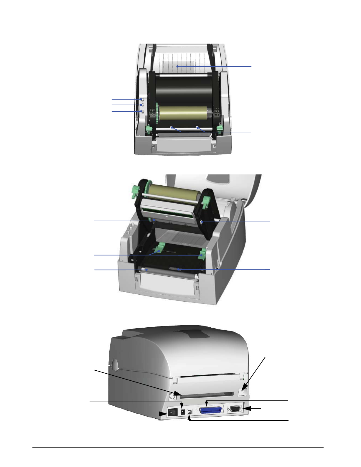
1.2 Printer Parts . . . . . . . . . . . . . . . . . . . . . . . . . . . . . . . . . . . . . . . . . . . . . . . . . . . . . . . . . . . . . . . . . . . . 1
2.0 Installation ................................................................................................................................... 3
2.1 Ribbon Installation . . . . . . . . . . . . . . . . . . . . . . . . . . . . . . . . . . . . . . . . . . . . . . . . . . . . . . . . . . . . . . . 3
2.2 Label Installation. . . . . . . . . . . . . . . . . . . . . . . . . . . . . . . . . . . . . . . . . . . . . . . . . . . . . . . . . . . . . . . . . 5
2.3 Label Roll Core Installation . . . . . . . . . . . . . . . . . . . . . . . . . . . . . . . . . . . . . . . . . . . . . . . . . . . . . . . . . 6
2.4 Cord/Hang Tags Installation . . . . . . . . . . . . . . . . . . . . . . . . . . . . . . . . . . . . . . . . . . . . . . . . . . . . . . . . 7
2.5 PC Connection. . . . . . . . . . . . . . . . . . . . . . . . . . . . . . . . . . . . . . . . . . . . . . . . . . . . . . . . . . . . . . . . . . 7
2.5.1 Store Format - Autoform Capability . . . . . . . . . . . . . . . . . . . . . . . . . . . . . . . . . . . . . . . . . . . . . . . . . . . . 8
2.5.2 Deleting the AUTOFR Form From the Printer . . . . . . . . . . . . . . . . . . . . . . . . . . . . . . . . . . . . . . . . . . . . . 8
3.0 Accessories ................................................................................................................................. 9
3.1 Stripper Module . . . . . . . . . . . . . . . . . . . . . . . . . . . . . . . . . . . . . . . . . . . . . . . . . . . . . . . . . . . . . . . . . 9
3.2 Cutter Installation . . . . . . . . . . . . . . . . . . . . . . . . . . . . . . . . . . . . . . . . . . . . . . . . . . . . . . . . . . . . . . . 13
3.3 CF Card Adapter Installation. . . . . . . . . . . . . . . . . . . . . . . . . . . . . . . . . . . . . . . . . . . . . . . . . . . . . . . 16
3.3.1 Using the CF Card. . . . . . . . . . . . . . . . . . . . . . . . . . . . . . . . . . . . . . . . . . . . . . . . . . . . . . . . . . . . . . . . 17
4.0 Control Panel ............................................................................................................................. 18
4.1 LED Status . . . . . . . . . . . . . . . . . . . . . . . . . . . . . . . . . . . . . . . . . . . . . . . . . . . . . . . . . . . . . . . . . . . . 18
4.2 Feed Key Introduction . . . . . . . . . . . . . . . . . . . . . . . . . . . . . . . . . . . . . . . . . . . . . . . . . . . . . . . . . . . 19
4.3 Self-Test. . . . . . . . . . . . . . . . . . . . . . . . . . . . . . . . . . . . . . . . . . . . . . . . . . . . . . . . . . . . . . . . . . . . . . 19
4.4 Auto-Sensing . . . . . . . . . . . . . . . . . . . . . . . . . . . . . . . . . . . . . . . . . . . . . . . . . . . . . . . . . . . . . . . . . . 19
4.5 Dump Mode . . . . . . . . . . . . . . . . . . . . . . . . . . . . . . . . . . . . . . . . . . . . . . . . . . . . . . . . . . . . . . . . . . . 20
4.6 Direct Thermal/Thermal Transfer Mode Switch . . . . . . . . . . . . . . . . . . . . . . . . . . . . . . . . . . . . . . . . . 20
4.7 See-Through Sensor On/Off. . . . . . . . . . . . . . . . . . . . . . . . . . . . . . . . . . . . . . . . . . . . . . . . . . . . . . . 20
4.8 Error Messages . . . . . . . . . . . . . . . . . . . . . . . . . . . . . . . . . . . . . . . . . . . . . . . . . . . . . . . . . . . . . . . . 21
5.0 Maintenance and Adjustments.................................................................................................. 22
5.1 Thermal Print Head Cleaning . . . . . . . . . . . . . . . . . . . . . . . . . . . . . . . . . . . . . . . . . . . . . . . . . . . . . . 22
5.2 Thermal Print Head Balance Adjustment . . . . . . . . . . . . . . . . . . . . . . . . . . . . . . . . . . . . . . . . . . . . . 22
5.3 Print Line Adjustment . . . . . . . . . . . . . . . . . . . . . . . . . . . . . . . . . . . . . . . . . . . . . . . . . . . . . . . . . . . . 23
5.4 Cutter Adjustment (Paper Jams). . . . . . . . . . . . . . . . . . . . . . . . . . . . . . . . . . . . . . . . . . . . . . . . . . . . 23
6.0 Appendix .................................................................................................................................... 24
6.1 Specifications . . . . . . . . . . . . . . . . . . . . . . . . . . . . . . . . . . . . . . . . . . . . . . . . . . . . . . . . . . . . . . . . . . 24
6.2 Compliance Statements . . . . . . . . . . . . . . . . . . . . . . . . . . . . . . . . . . . . . . . . . . . . . . . . . . . . . . . . . . 25
6.3 Parallel Interface . . . . . . . . . . . . . . . . . . . . . . . . . . . . . . . . . . . . . . . . . . . . . . . . . . . . . . . . . . . . . . . . 26
6.4 Serial Interface . . . . . . . . . . . . . . . . . . . . . . . . . . . . . . . . . . . . . . . . . . . . . . . . . . . . . . . . . . . . . . . . . 26
6.5 USB Interface . . . . . . . . . . . . . . . . . . . . . . . . . . . . . . . . . . . . . . . . . . . . . . . . . . . . . . . . . . . . . . . . . . 26
6.6 Internal Interface. . . . . . . . . . . . . . . . . . . . . . . . . . . . . . . . . . . . . . . . . . . . . . . . . . . . . . . . . . . . . . . . 26
6.7 Troubleshooting . . . . . . . . . . . . . . . . . . . . . . . . . . . . . . . . . . . . . . . . . . . . . . . . . . . . . . . . . . . . . . . . 27
RL-42TT Limited Warranty...................................................................................................................... 28
© 2008 Rice Lake Weighing Systems. All rights reserved. Printed in the United States of America.
Specifications subject to change without notice.
November 2008
5FDIOJDBMUSBJOJOHTFNJOBSTBSFBWBJMBCMFUISPVHI3JDF-BLF8FJHIJOH4ZTUFNT
$PVSTFEFTDSJQUJPOTBOEEBUFTDBOCFWJFXFEBUXXXSJDFMBLFDPNPSPCUBJOFECZ
DBMMJOHBOEBTLJOHGPSUIFUSBJOJOHEFQBSUNFOU

ii RL-42TT Operation Manual

Introduction 1
About This Manual
This manual is intended for use by qualified service
technicians responsible for installing and servicing the
RL-42TT printer.
Authorized distributors and their employees
can view or download this manual from the
Rice Lake Weighing Systems distributor
site at www.ricelake.com.
Warning
Danger of explosion if battery is
incorrectly replaced. Replace only with
the equivalent type recommended by the
manufacturer. Dispose of batteries
according to the manufacturer’s
instructions.
1.0 Introduction
After unpacking, check to make sure all accessories are included:
• Barcode printer
• Power cord
• Switching power
• USB cable
• Label
•Ribbon
• Empty ribbon roll
•Cleancard
1.1 Safety Instructions
• Keep the equipment away from humidity.
• Before you connect the equipment to the power outlet, check the voltage of the power source.
• Disconnect the equipment from the voltage of the power source to prevent possible transient
over-voltage damage.
• Don’t pour any liquid near the equipment, as it may result in electric shock.
• Only qualified service personnel should open the equipment.
• Don’t repair or adjust energized equipment alone under any circumstances. Someone capable of
providing first aid must always be present for your safety.
1.2 Printer Parts
Cover open button
Label roll core
Ribbon rewind wheel
Print mechanism
Ribbon rewind shaft + Empty ribbon roll
Locking tenon (left/right)
Front cover piece
Figure 1-1. Top cover lifted, printer parts illustrated

CF Card slot cover
Print head pressure
adjustment screw (left/right)
LED light (ready)
LED light(status)
FEED key
2RL-42TT Operation Manual
Figure 1-2. Inside of printer
Ribbon supply shaft
Label guide
Platen roller
Print line adjustment
gear
Label sensor
Figure 1-3. Inside of printer, print mechanism lifted
Ethernet port (option)
Fan-fold label insert
Power switch
Power socket
USB port
Parallel port
Serial (RS-232) port
Figure 1-4. Back of printer

Installation 3
2.0 Installation
This section contains information on installing the ribbon, labels, label roll core and cord/hang tags. It also
contains instructions on connecting to a PC.
2.1 Ribbon Installation
1. Place the printer on a horizontal surface.
2. Open the top cover by pressing the cover
open buttons on both sides and lifting.
3. Loosen and lift the upper print
mechanism by pressing the locking
tenons.
4. Place a new ribbon roll onto the ribbon
supply shaft.

4RL-42TT Operation Manual
5. Feed the ribbon from the ribbon supply
shaft under the print head.
6. Wrap the ribbon around the ribbon shaft
and stick the ribbon onto the empty
ribbon roll core.
7. Close the upper print mechanism from
the top to finish ribbon installation.

Installation 5
2.2 Label Installation
1. Open the top cover by pressing the cover
open buttons on both sides and lifting.
2. Place the label roll onto the label roll
core.
3. Loosen and lift the upper print
mechanism by pressing the locking
tenons.
4. Feed the label through the two label
guides to the tear-off bar.
5. Align the label guides to the label edge.
6. Close the upper print mechanism from
the top to finish label installation.

6RL-42TT Operation Manual
2.3 Label Roll Core Installation
1” roll core installation
1.5” roll core installation
3” roll core installation

Installation 7
2.4 Cord/Hang Tags Installation
When installing cord tags, the tag hole must align with the sensor arrow as indicated in Figure 2-2. Then, use the
label guide to secure the tags.
Sensor
Tag hole position
Sensor Detection Position
Figure 2-1. Sensor detection position and sensor location
2.5 PC Connection
1. Make sure the printer is powered off.
2. Take the power cable, plug the cable switch to the power socket, then connect the other end of the cable
to the printer power socket.
3. Connect the cable to the USB/parallel port on the printer and on the PC.
4. Power on the PC and printer. The printer’s LED light will turn on.
Figure 2-2. PC connection illustration

8RL-42TT Operation Manual
2.5.1 Store Format - Autoform Capability
1. Design the form in Label View and save it as AUTOFR.
2. Generate a command file.
3. Exit Label View and bring up the file in Dos Edit (the file is AUTOFR.EJF).
4. Add a line at the beginning and add the interrupt command. This is added by holding down the CTRL
key and pressing the P, and then the S keys. Two exclamation points should appear at the beginning of
the line.
5. Add before PE the command PA1.
6. Turn the printer off for a minute and then on again to make sure the buffer is empty.
7. Download the form to the printer by choosing Print from Dos Edit.
This is now the form that will be printed every time the print button is pushed. This example works with only one
variable field, which means that only gross or only net weight can be printed. Once this form is loaded in the
printer the customer cannot use the printer for any other label format.
2.5.2 Deleting the AUTOFR Form From the Printer
1. Turn the printer off for a minute, then turn it back on.
2. Send the interrupt command, CTRL S, and then FK"*".
This will delete all stored forms from the printer memory.
This will open up doors for a simple label application, and works with most devices that are sending a single
weight and capable of 9600 baud, 8 data bits.

Accessories 9
3.0 Accessories
3.1 Stripper Module
The stripper module separates a label from its backing, allowing the user to apply a label without peeling.
To install the stripper module, follow these instructions:
1. Make sure you have the module and two
provided screws.
2. Power off the printer before installing the
stripper module.
2
1
NOTES: Label liner thickness is recommended to be
0.06 mm ± 10% with basic weight 65g/m2± 6%.
The maximum width for the stripper is 110 mm.
When using the stripper module, it is recommended to
set the stop position to 9 in QLabel and the E value is 9.
3. Place the printer on a horizontal surface
and open the top cover by pressing the
cover open buttons on both sides and
lifting upward.
4. Loosen and then lift the upper print
mechanism by pressing the locking
tenons.

10 RL-42TT Operation Manual
5. Unlock the front cover piece by pushing
locks inward.
6. Lift/take off the front cover piece
according to the figure shown at the
right.
7. Plug in the stripper module’s connector
to the switchboard socket.
NOTE: There are two sockets on the converting boards.
One is for stripper module installation, and the other is
for the cutter. Before you plug the connector into the
socket, check the pin first.
8. Place the left side of the stripper module
first, then fit the right side.
9. Hold the stripper module in place and
tighten the screws to secure its location.

Accessories 11
10. Feed the label through the label guides.
NOTE: The label/paper used for rewinding purpose is
suggested to be at least 30 mm in height.
11. Peel off the first label and feed the liner
through the roller and the tear-off bar.
12. Follow the direction shown in the figure
at the right to feed the liner across the
stripper module.

12 RL-42TT Operation Manual
13. Close the upper print mechanism and the
stripper module.
14. Press the FEED key to adjust the position
of the label and complete the installation.

Accessories 13
3.2 Cutter Installation
The RL-42TT printers feature a photo-eye, which detects gaps between labels. When a gap is detected, the cutter
will separate the label from the roll. To install the cutter, follow these instructions:
1. Make sure you have the cutter module
and two provided screws (TAP 3*8).
2. Power off the printer before installing the
cutter module.
2
1
NOTES: Do not cut self-adhesive labels! The traces of
adhesive will pollute the rotary knife and impair safe
operation.
The service life of the cutter is 500,000 cuts for paper
weights up to 160g/m2, and 250,000 cuts for paper
weights 200g/m2paper weight.
3. Place the printer on a horizontal surface
and open the top cover by pressing the
cover open buttons on both sides and
lifting upward.
4. Loosen and then lift the upper print
mechanism by pressing the locking
tenons.

14 RL-42TT Operation Manual
5. Unlock the front cover piece by pushing
locks inward.
6. Lift/take off the front cover piece
according to the figure shown at the
right.
7. Plug in the cable connector of the cutter
module to the switchboard socket.
NOTE: Before you plug the connector to the socket,
check the pin
8. Place the left side of the stripper first,
and then fit the right side.
9. Flip the cutter module downward to open
the cutter.

Accessories 15
10. Hold the cutter module and lock it with
screws.
11. After the screws are locked, flip close the
cutter module.
12. Feed the label through the label guides.
13. Close the mechanism.
14. Press the FEED key to adjust the position
of the label and complete the installation.

16 RL-42TT Operation Manual
3.3 CF Card Adapter Installation
The RL-42TT printer can use a compact flash (CF) card for additional memory in storing label formats, graphics,
and fonts. The CF card adapter, shown in Figure 3-1, must first be installed. The printer supports CF capacities
from 128MB to 1GB. Always power off the printer before installing or removing the CF card from the card slot.
Figure 3-1. CF card adapter front (left) and back (right)
1. Place the printer on a horizontal surface
and open the top cover by pressing the
cover open buttons on both sides and
lifting upward.
2. Take off the label roll core.
3. Open and remove the plastic cover from
the inner base.
Table of contents
Other Rice Lake Printer manuals

Rice Lake
Rice Lake Uni-9 Series User manual

Rice Lake
Rice Lake TicketPress User manual

Rice Lake
Rice Lake ATK User manual

Rice Lake
Rice Lake TicketPress Parts list manual

Rice Lake
Rice Lake SST4 User manual

Rice Lake
Rice Lake SP2200 User manual

Rice Lake
Rice Lake TM-U590 User manual

Rice Lake
Rice Lake Prove User manual

Rice Lake
Rice Lake 5000 Series Owner's manual

Rice Lake
Rice Lake RL-HPJ Manual