2
2. Front Panel Indicators
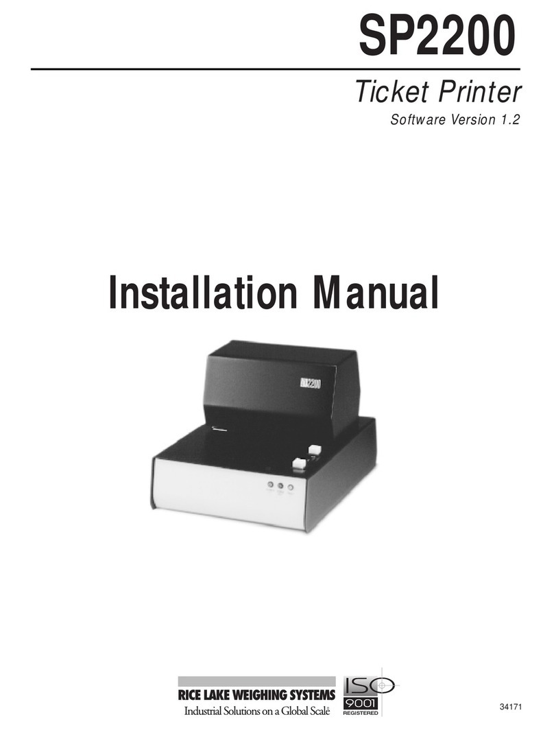
The three LED indicators on the SP2200 front panel are used as follows:
POWER (green LED) Indicates that the printer is connected to a power source and the rear panel
power switch is on.
FORM OUT (red LED) Indicates that there is no ticket in the printer. This indicator is active only if
the paper sensor is set on.
FAULT (amber LED) Indicates that the time and date or ID code information being entered is either
incomplete or invalid. The FAULT LED is normally lit when using the
switch module to enter this information. When the entry is complete, the
LED turns off.
3. Switch Module Command Summary
The following table provides a summary of switch module command formats used to set the time and date, ID
codes and the number of line feeds between print requests.
Command Function Format
FSet Time and Date FhhmmxMMDDYY or FhhmmDDMMYY
Enter using US or International format as configured by DIP
switch 2-6 (0=International, 1=US format).
For US format, x=am/pm indicator, where 0=am, 8=pm.
Clear Time and Date FCCCCCCCCCCCC
ESet ID Code Ennnnnnnn
Clear ID Code ECCCCCCCC
DSet Incrementing ID/Line Feeds Dxxy
xx=line feeds; y=number of digits incremented
4. Fuse Replacement
To replace fuses in the SP2200, do the following:
1. Turn off the printer and disconnect the
power cord.
2. Use a small, flat-head screwdriver to lift
the cover of the fuse compartment (see
Figure 4).
3. Use the screwdriver to lift the fuseholder
out of the compartment.
4. Replace either or both of the fuses, as
required. Use 1.25A 3AG Slo-Blo fuses
for 115V models, 0.75A 3AG Slo-Blo for
230V models.
5. Slide the fuseholder back into the fuse
compartment. Press down until the fuseholder snaps in place.
6. Close the fuse compartment cover and reconnect the power cord.
LINE
LIFT
Figure 4. Cover of SP2200 fuse compartment
