Technical Bulletin No. RTB-001
SUBJECT:Software Modification DATE: May 15, ’92
PAGE: 1 of 2
PREPARED BY: S. Orita
CHECKED BY: FROM: Copier Technical Support Section
CLASSIFICATION:
Action Required
Troubleshooting
Retrofit Information
Revision of service manual
Information only
Other
MODEL: E7 series
(A076/A077/A078)
Because of software changes, the ROM has been changed for the A076/A077/A078
copiers. Because of the part number change for the ROM, the part number for the main
board also has been changed. All changes are in effect from the first mass production.
The changes are listed below.
1. Main Board #A0775101 to #A0775111 (for A077/A078 copiers)
2. Main Board #A0765101 to #A0765111 (for A076 copier)
3. ROM #A0775104 to #A0775105 (for A076/A077/A078 copiers)
Details of software changes
1. How to reset "J1" indicator
The J1 indicator is used for paper misfeed and paper end. The indicator can now be reset
two ways: by opening and closing the front cover, or by opening and closing the paper
tray. (Previously, opening and closing the paper tray had no effect.)
2. The VL correction factor is newly added to the exposure lamp voltage control. (Refer to
page 2 - 19 of the service manual.)
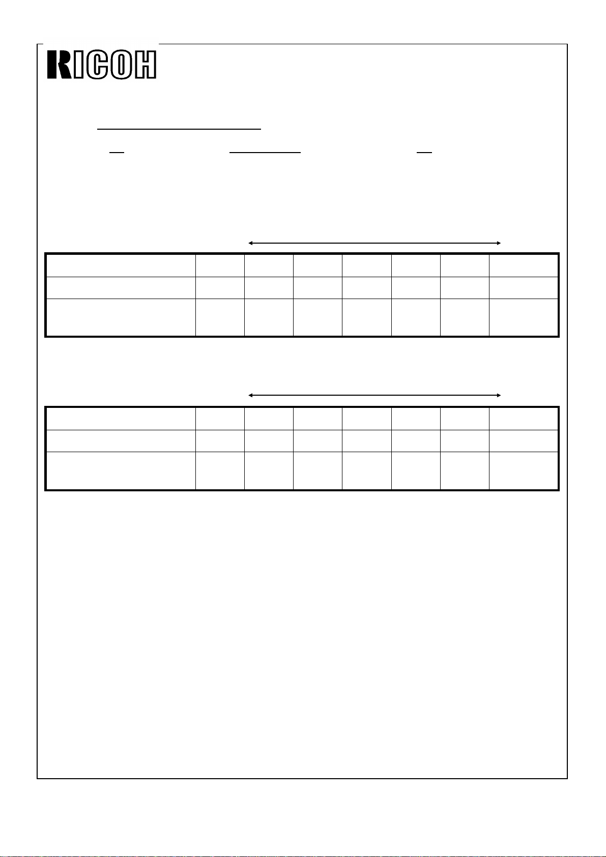
VL Correction Factor
The light intensity may decrease because of dust accumulated on the optics parts. The
exposure lamp data is increased by one (1) every 4,000 copies (factory setting) to
compensate for this . The VL correction is applied until the exposure lamp data (SP51)
rearches its maximum of 145. The following SP modes for the VL correction are newly
added: Mode No. Function Data
81 VL Correction
Interval Sets the interval of VL correction 0: every 4K copies
1: every 2K copies
2: every 1K copies
3: every 500 copies
4: No correction
Do not change the data more than one
(1) step at a time.
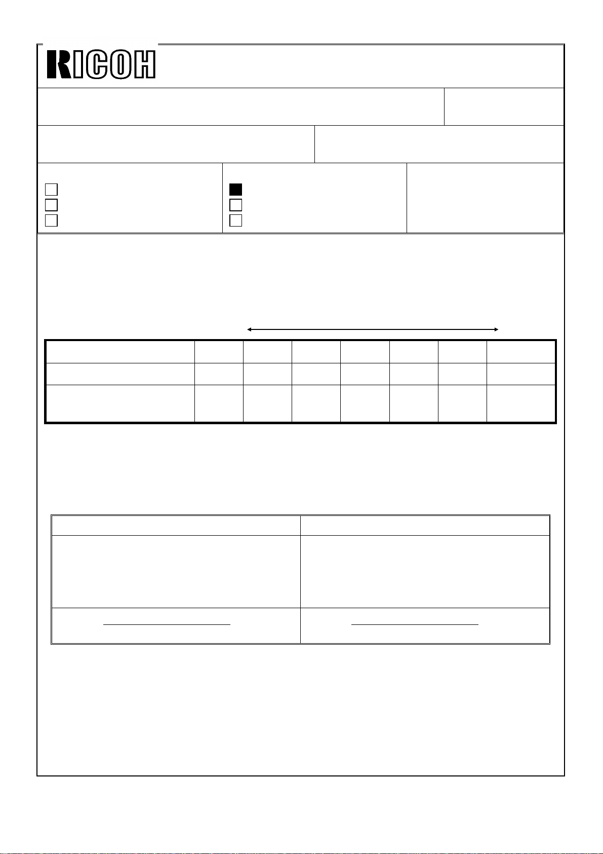
95 VL Correction
Reset Resets the exposure lamp data and
counter for the VL correction. 0: No
1: Yes
VL correction reset should always be
done before the light intensity
adjustment (SP48) is performed.