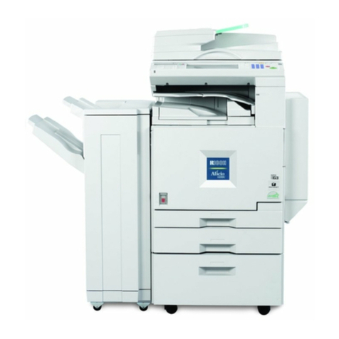
Ricoh FT4220 Installation guide

FT4220/4222/4215
SERVICE TRAINING MANUAL

IMPORTANT SAFETY NOTICES
PREVENTION OF PHYSICAL INJURY
1. Before disassembling or assembling parts of the copier and peripherals,
make sure that the copier power cord is unplugged.
2. The wall outlet should be near the copier and easily accessible.
3. Note that some components of the copier and the paper tray unit are
supplied with electrical voltage even if the main switch is turned off.
4. If any adjustment or operation check has to be made with exterior covers
off or open while the main switch is turned on, keep hands away from
electrified or mechanically driven components.
5. The inside and the metal parts of the fusing unit become extremely hot
while the copier is operating. Be careful to avoid touching those
components with your bare hands.
HEALTH SAFETY CONDITIONS
1. Never operate the copier without the ozone filter installed.
2. Always replace the ozone filter with the specified one at the specified
interval.
3. Toner and developer are non-toxic, but if you get either of them in your
eyes by accident, it may cause temporary eye discomfort. Try to remove
with eye drops or flush with water as first aid. If unsuccessful, get medical
attention.
OBSERVANCE OF ELECTRICAL SAFETY STANDARDS
1. The copier and its peripheral must be installed and maintained by a
customer service representative who has completed the training course
on those models.
-- CAUTION --
2. The RAM pack has a lithium battery which can explode if handled
incorrectly, replace only with same RAM pack. Do not recharge, or burn
this battery. Used RAM pack must be handled in accordance with local
regulations.

SAFETY AND ECOLOGICAL NOTES FOR DISPOSAL
1. Do not incinerate the toner cartridge or the used toner. Toner dust may
ignite suddenly when exposed to open flame.
2. Dispose of used toner, developer, and organic photoconductors
according to local regulations. (These are non-toxic supplies.)
3. Dispose of replaced parts in accordance with local regulations.

MAJOR DIFFERENCES BETWEEN THE FT4220/4222 AND FT4418/4421 SERIES
The FT4220/4222 were developed based on the FT4418/4421.
The following table shows the major differences between the FT4220/4222 and the
FT4418/4421 series.
No. Section/Item FT4220/4222
(A110 and A111) FT4418/4421
(A048 and A054)
Major Features
1Copy Speed FT4220:
20 copies/minute
(A4/11" x 81/2" sideways)
10 copies/minute (A3/11" x 17")
FT4418
18 copies/minute
(A4/11" x 81/2" sideways)
10 copies/minute (A3/11" x 17")
FT4222
22 copies/minute
(A4/11" x 81/2" sideways)
11 copies/minute (A3/11" x 17")
FT4421
20 or 21 copies/minute
(A4/11" x 81/2" sideways)
11 copies/minute (A3/11" x 17")
2Energy Saver
Function The energy saver function
reduces power consumption by
decreasing the fusing
temperature when the copier is
not in use.
The energy saving ratio can be
changed by SP mode.
The automatic energy saver
mode is selected by SP mode.
----
3User Program
Mode FT4220 Yes
FT4222 Yes FT4418 No
FT4421 Yes
4Edge Erase,
Center Erase,
Edge/Center
Erase
The edge erase, center erase
and edge/center erase modes
are added as preset user
program modes.
The erase margin can be
changed by SP mode.
----
Copier Installation
1Shipping
Retainers The following shipping retainers
are removed to reduce the
installation time:
•Optics Lock Pins
•Scanner Lock Plate and Plugs
•Drum Protective Sheet
----
2Toner Supply
Unit Initial
Setting (SP63)
The toner supply unit initial
setting (SP63) is not required.
For the color development unit
installation, SP63 must be
performed as for the FT4418
series.
SP63 must be performed to
prevent toner end from being
falsely detected because the
toner supply unit is empty.
1

No. Section/Item FT4220/4222
(A110 and A111) FT4418/4421
(A048 and A054)
Peripheral
1Duplex Unit The duplex unit is unique to the
Pigeon series.
The differences from the FT4418
series duplex unit are as follows:
The duplex unit for the Pigeon
series cannot be installed on the
FT4418 series.
1) A projection is added to
actuate all the paper size
switches.
2) Duplex front cover
3) Duplex main board
(Communication signal between
the duplex and copier main
boards is different from the
FT4418 series.)
4) A ground wire is added to the
duplex frame in order to absorb
electrical noise.
The duplex unit for the FT4418
series cannot be installed on the
Pigeon series.
2Optional DC
Power Supply
Unit
FT4220 only
The optional dc power supply
unit (Model Code: A525) is
unique to the FT4220. The
optional dc power supply unit
consists of the following parts:
•DC power supply board
•Transformer
•DF interface harness
The optional dc power supply
unit is required when the DF
and/or duplex unit is installed on
the FT4220.
FT4418 only
The optional dc power unit
(Model Code: A494) consists of
the following parts:
•DC power supply board
•Transformer
•Interface board
•DF/Sorter/Duplex interface
harness
The optional dc power supply
unit is required when the DF,
duplex, and/or sorter is installed
on the FT4418.
Peripheral Installation
2

No. Section/Item FT4220/4222
(A110 and A111) FT4418/4421
(A048 and A054)
1Sorter
Installation The optional dc power supply
unit (A525) is not required.
The interface harness is an
accessory of the sorter.
FT4418:
The optional dc power supply
unit (A494) is required.
The sorter interface harness is
an accessory of the optional dc
power supply unit.
FT4421:
The optional dc power supply
unit and the sorter interface
harness are installed on the
machine at the factory.
2DF Installation FT4220:
The optional dc power supply
unit (A525) is required.
The DF interface harness is an
accessory of the optional dc
power supply unit.
FT4418:
The optional dc power supply
unit (A494) is required.
The DF interface harness is an
accessory of the optional dc
power supply unit.
FT4222:
The optional dc power supply
unit is not required.
The DF interface harness is not
required either.
FT4421:
The optional dc power supply
unit and the DF interface
harness are installed on the
machine at the factory.
3Duplex
Installation FT4220:
The optional dc power supply
unit (A525) is required.
The duplex harness is an
accessory of the duplex unit.
FT4418:
The optional dc power supply
unit (A494) is required.
The duplex interface harness is
an accessory of the optional dc
power supply unit.
FT4222:
The optional dc power supply
unit is not required.
The duplex interface harness is
an accessory of the duplex unit.
FT4421:
The optional dc power supply
unit and the duplex interface
harness are installed on the
machine at the factory.
Drum
1Drum The drum is common with that of
the FT5733 and FT4727 series.
The expected yield is increased
to 80K copies.
The expected yield is 60K copies.
Drum Charge
3

No. Section/Item FT4220/4222
(A110 and A111) FT4418/4421
(A048 and A054)
1Vp Correction The interval of the grid voltage
increment is changed as the
drum changes.
Drum Counter Vp Correction
Factor
0 to 1,999 copies ±0 volt
Over 2,000 copies --20 volts
Drum Counter Vp Correction
Factor
0 to 999 copies ±0 volt
1,000 to 1,999 copies --20 volts
Over 2,000 copies --40 volts
Optics
11st Scanner The configuration of the main
and sub reflectors is changed.
The proportion of the light
reflected from the main and sub
reflectors is almost 50% each.
Under this condition, both the
lead and trail edges of the
pasted parts of an original will
not make shadows. This
mechanism is the same as for
the FT4727 series.
The light intensity reflected from
the main reflector is stronger
than that reflected from the sub
reflector (about 65% to 35%).
2Dirty
Background
Copy
To prevent the dirty backgrounds
on copies caused by dust
accumulated on optics parts, the
following items are modified.
----
1) The toner shield glass is
removed and a green color filter
is installed on the lens unit.
2) VLcorrection is added. The
exposure voltage increases at
set intervals of the machine on
time.
3Drum Wear
Correction The interval of the exposure
lamp voltage increment is
changed because the drum is a
new type.Same as FT5733/4727.
FT5733 drum cannot be used in
FT4418 due to diffrences in
drum wear correction.
Drum rotation Change of
time exposure lamp
data
0 to 24h ±0
25 to 49h +1
50 to 74h +2
75 to 99h +3
More than 99h +4
Drum rotation Change of
time exposure lamp
data
0 to 9h ±0
10 to 19h +1
20 to 29h +2
::
::
More than 80h +8
4
No. Section/Item FT4220/4222
(A110 and A111) FT4418/4421
(A048 and A054)
4Green Filter A green filter has been added
before the lens, to enable red
originals to be copied with
greater contrast.
----
5Scanner Motor
Drive Circuit The scanner motor drive circuit
is located on the ac drive board.
The main board sends the
control signal to the scanner
motor drive circuit to regulate the
scanner motor speed.
The main board directly controls
the scanner motor.
Development
1Bias Voltage in
ADS mode The number of base bias voltage
levels corresponding to the ADS
output voltage is increased (6
levels).
This change will minimize the
possibility of dirty background
copies with the various originals.
This change also helps to
prevent dirty background copies
caused by dust accumulated on
the exposure glass, 1st, 2nd,
and 3rd mirrors.
4 levels
2Development
Unit Set Sensor No Yes
Toner Density Detection And Toner Supply
1Black Toner
End Detection The ID sensor is used for black
toner end detection.
The black development unit for
the Pigeon series cannot be
used for the FT4418 series.
The toner end detection for the
color toner is the same as that of
the FT4418 series.
The toner end sensor is used for
both black and color toner end
detection. The ID sensor is used
as a back-up system
2Black Toner
End Recovery If the front cover is opened and
closed, or the main switch is
turned off and on in the near end
and toner end conditions, no
copy can be made.
For the color toner, only one
copy can be made (same as for
the FT4418 series).
Only one copy can be made in
black and color.
5

No. Section/Item FT4220/4222
(A110 and A111) FT4418/4421
(A048 and A054)
Cleaning
1Cleaning Blade The plate on the rubber blade is
removed. ----
2Toner
Overflow
Sensor
Same as FT4418
Paper Feed
1Paper Size
Detection in
2nd and 3rd
Feed Station
The paper size switches are
actuated by a paper size
detection block. To change the
paper size, it is necessary to set
the paper size detection block of
the paper tray to match the
paper size.
When the paper end guide is
pushed against the paper stack,
the actuator plate slides into
position and actuates the
appropriate paper size switches.
22nd and 3rd
Paper Feed
Roller
To achieve 22 CPM from the 3rd
paper feed station, the stop
angle of the paper feed roller is
changed.
To prevent the corner of the feed
roller from hitting the paper stack
when the paper tray is pulled
out, the corner of the paper feed
roller is cut.
----
3Corner
Separators on
Paper Tray
To reduce the occurrence of dog
ear and double feed, the shape
of the corner separators on the
paper tray is changed.
----
4Tray Lock
Solenoid No
U7 is displayed when the duplex
unit is opened during the duplex
operation.
Yes
Others
1RAM Clear To prevent false RAM clear, the
following items are modified. ----
1) To minimize electrical noise,
the main board is secured by
four ground screws.
2) Optional equipment is on the
main board.
6

MAJOR UNIQUE PARTS FOR PIGEON SERIES
(Compare with FT4418 Series)
PM Parts
Parts Number Description Remarks
A0699510 Drum Common with the FT5733 series
A0063570 Cleaning Blade Common with the FT4460
A1109500 Paper Feed Roller (4 pcs/set) for
2nd and 3rd feed stations. This roller will be used for the
FT4418 series.
AA010072 Ozone Filter This ozone filter will be used for
the FT4418 series.
Electrical Parts
Parts Number Description Remarks
A1105160 Main Board for FT4220
A1115160 Main Board for FT4222
AZ230039 DC Power Supply Board for
FT4222 DC power supply for FT4222
same as FT4418
A1115520 AC Drive Board - 115 V
A1115620 AC Drive Board - 220 V
AZ320069 Power Pack - CC/Grid/Bias
AX530017 Exposure Lamp - 115 V
AX530016 Exposure Lamp - 220 V
A1105235 Erase Lamp
AX440066 Fusing Lamp - 115 V
AX440067 Fusing Lamp - 220 V
A1105640 Noise Filter Board (for 220 V only)
AX200095 Registration Clutch
Relay Roller Clutch
A1105214 Scanner Motor
A1105550 Operation Panel Ass’y
- LT, FT4220(Ricoh)
A1115551 Operation Panel Ass’y
- LT, FT4222 (Ricoh)
A1105650 Operation Panel Ass’y
- A4, FT4220(Ricoh)
A1115651 Operation Panel Ass’y
- A4, FT4222 (Ricoh) Electrical Spring Type Magnetic
Clutch.
A1106692 Operation Panel Ass’y
- FT4220(SAVIN)
A1116692 Operation Panel Ass’y
- FT4222 (SAVIN)
A1106492 Operation Panel Ass’y
- LT, FT4220(GES)
7

Parts Number Description Remarks
A1116492 Operation Panel Ass’y
- LT, FT4222 (GES)
A1106292 Operation Panel Ass’y
- A4, FT4220(GES)
A1116292 Operation Panel Ass’y
- A4, FT4222 (GES)
A1106094 Operation Panel Ass’y
- FT4220(Infotec)
A1116094 Operation Panel Ass’y
- FT4222 (Infotec)
8

SECTION 1
OVERALL MACHINE
INFORMATION

1. SPECIFICATIONS
Configuration: Desk top
Copy Process: Dry electrostatic transfer system
Originals: Sheet/Book
Original Size: Maximum: A3/11" x 17"
Copy Paper Size: Maximum: A3/11" x 17"
Minimum: A6/51/2" x 81/2" (lengthwise)
..... Manual and cassette feeds
A5/11" x 81/2" (sideways)
..... Paper tray feed
(Duplex Copying) A4/11" x 81/2" (sideways)
Copy Paper Weight: Cassette feed: 52 to 157 g/m2(14 to 42 lb)
Paper tray feed: 64 to 90 g/m2(17 to 22 lb)
Manual feed: 52 to 157 g/m2(14 to 42 lb)
Duplex: 58 to 104 g/m2(16 to 28 lb)
Reproduction Ratio: 2 Enlargement and 3 Reduction
A4/A3 version LT/LDG version
Enlargement 141%
122% 155%
129%
Full size 100% 100%
Reduction 93%
82%
71%
93%
74%
65%
Zoom: From 50% to 200% in 1% steps
Copying Speed: (FT4220 copier)
20 copies/minute (A4/11" x 81/2" sideways)
10 copies/minute (A3/11" x 17")
(FT4222 copier)
22 copies/minute (A4/11" x 81/2" sideways)
11 copies/minute (A3/11" x 17")
Warm-Up Time: Less than 60 seconds (at 20°C)
First Copy Time: 5.9 seconds (A4/11" x 81/2" sideways for cassette
feed)
Copy Number Input: Ten keys, 1 to 99 (count up)
STM 1-1 FT4220/4222

Manual Image Density
Selection: 7 steps
Automatic Reset: All input modes are reset 1 minute after the copier
is not in use; can also be set to 3 minutes or no
auto reset.
Energy Saver Function: Saving the electricity consumption
(Manual or manual/auto)
Paper Capacity: Cassettes: 500 sheets
Paper tray: 250 sheets
(FT4220 copier ... 1 paper tray)
(FT4222 copier ... 2 paper trays)
Manual feed table: 50 sheets
Toner Replenishment: Black: Cartridge exchange (370g/cartridge)
Color (red, blue, & green):
Cartridge exchange (310 g/cartridge)
Developer
Replenishment: Black (1KG/bag.) Yeild 60000 copies.
Color (1KG/bag.) Yeild 30000 copies.
Copy Tray Capacity: 250 sheets (B4/81/2" x 14" and smaller)
100 sheets (A3/11" x 17")
Power Source: 110 V/ 60 Hz/ 15 A (for Taiwan)
115 V/ 60 Hz/ 15 A (for North America)
220/230/240 V/ 50 Hz/ 8 A (for Europe)
220 V/ 60 Hz/ 8 A (for Middle East)
(Refer to the serial number plate (rating plate) to
determine the power source required by the
machine.)
Power Consumption:
FT4220 copier FT4222 copier
Maximum 1.2 kVA 1.3 kVA
Warm-up 720 VA (average) 720 VA (average)
Copy cycle 810 VA (average) 830 VA (average)
Stand-by
(without energy
saver function)
160 VA (average) 160 VA (average)
YIELD 9500 COPIES
YIELD 6000 COPIES
FT4220/4222 1-2 STM

Dimensions:
Width Depth Height
Copier only FT4220
copier 672 mm (1130 mm)
26.5" (44.5") 600 mm
23.7" 410 mm (464 mm)
16.1" (18.3")
FT4222
copier 672 mm (1130 mm)
26.5" (44.5") 600 mm
23.7" 530 mm (584 mm)
20.9" (23.0")
Full system FT4220
copier 1149 mm
45.3" 600 mm
23.7" 513 mm
20.2"
FT4222
copier 1149 mm
45.3" 600 mm
23.7" 633 mm
25.0"
( ): when the cassette and platen cover are installed and the copy tray is extended.
Noise Emissions:
Maximum Copy cycle Stand-by
Copier only less than 58 dB less than 55 dB less than 40 dB
Full system less than 60 dB less than 58 dB less than 40 dB
Weight:
FT4220 copier FT4222 copier
Copier only 55 kg (121.3 lb) 64 kg (141.1 lb)
Full system 78 kg (172 lb) 83.5 kg (184 lb)
Optional Equipment and Machine Configuration: ( ) Machine Code
Configuration Optional dc power supply unit (A525)
Main frame Optional equipment Required Not required
FT4220
copier
(A110)
CS110 10 bin sorter (A490) O
DF57 Document feeder (A318) O
AD130 Duplex unit (A491) O
Color development unit (A313) O
FT4222
copier
(A111)
CS110 10 bin sorter (A490) O
DF57 Document feeder (A318) O
AD130 Duplex unit (A491) O
Color development unit (A313) O
Other Optional Equipment:• Key counter
• Universal cassette
• Optics anti-condensation heater
•Specifications are subject to change without notice.
STM 1-3 FT4220/4222

2. COPY PROCESSES AROUND THE DRUM
4. DEVELOPMENT
5. PRE-TRANSFER LAMP
6. IMAGE TRANSFER
7. PAPER
3. ERASE
2. EXPOSURE
1. DRUM CHARGE
9. QUENCHING
8. CLEANING
SEPARATION
(PTL)
FT4220/4222 1-4 STM

1. DRUM CHARGE
In the dark, the charge corona unit gives a uniform negative charge to the organic
photoconductive (OPC) drum. The charge remains on the surface of the drum because the
OPC drum has a high electrical resistance in the dark.
2. EXPOSURE
An image of the original is reflected to the OPC drum surface via the optics assembly. The
charge on the drum surface is dissipated in direct proportion to the intensity of the reflected
light, thus producing an electrical latent image on the drum surface.
3. ERASE
The erase lamp illuminates the areas of the charged drum surface that will not be used for
the copy image. The resistance of the drum in the illuminated areas drops and the charge on
those areas dissipates.
4. DEVELOPMENT
Positively charged toner is attracted to the negatively charged areas of the drum, thus
developing the latent image. (The positive triboelectric charge is caused by friction between
the carrier and toner particles.)
5. PRE-TRANSFER LAMP (PTL)
The PTL illuminates the drum to remove all negative charge from the exposed areas of the
drum. This prevents the toner particles from being reattracted to the drum surface during
paper separation and makes paper separation easier.
6. IMAGE TRANSFER
Paper is fed to the drum surface at the proper time so as to align the copy paper and the
developed image on the drum surface. Then, a strong negative charge is applied to the back
side of the copy paper, producing an electrical force which pulls the toner particles from the
drum surface to the copy paper. At the same time, the copy paper is electrically attracted to
the drum surface.
7. PAPER SEPARATION
A strong ac corona discharge is applied to the back side of the copy paper, reducing the
negative charge on the copy paper and breaking the electrical attraction between the paper
and the drum. Then, the stiffness of the copy paper causes it to separate from the drum
surface. The pick-off pawls help to separate paper.
8. CLEANING
The cleaning brush removes most of the toner on the drum and loosens the remainder. Then
the cleaning blade scrapes off the loosened toner.
9. QUENCHING
Light from the quenching lamp electrically neutralizes the surface of the drum.
STM 1-5 FT4220/4222

3. COPY PROCESS CONTROL
Grid Voltage Exposure Lamp
Voltage Development Bias
Voltage Erase Lamp
Image
Density
Control
Standard image
density grid
voltage (–920V)
+
Drum residual
voltage (Vr)
correction factor
(SP67) +
+
Drum wear correction
factor (SP58)
+
Reproduction ratio
correction factor
Base bias voltage
1. Manual mode
+
+
Drum residual voltage
(Vr) correction factor
(SP67)
Depending
on paper
size and
reproduction
ratio
Toner
Density
Detection
Standard ID
sensor grid
voltage (–560V)
+
Vp correction
factor (SP69)
Same as image
density control
+
Vd correction factor
(Black only) (SP64)
ID sensor
pattern
erase (Vsg
detection:
Full erase)
Residual
Voltage
(Vr)
Detection
–500 bolts
(Fixed) Same as image
density control 0 volt (Fixed) Full erase
(All LEDs
ON)
Between
Copies
(Non-
image
area)
0 volt (Fixed) Exposure lamp turns
off –200 volts (Fixed)
+
+
Drum residual voltage
(Vr) correction factor
(SP67)
Full erase
(All LEDs
ON)
NOTE: a) Boxed items can be adjusted by SP modes surrounded by square
brackets [ ].
b) Data which determines the correction factor can be observed by
SP modes surrounded by parenthesis ( ).
Base exposure lamp
voltage
1. Manual mode
[SP48]
2. ADS mode [SP48]
and [SP34]
VLcorrection factor
[SP61] and [SP57]
2. ADS mode
[SP34]
Base bias voltage
adjustment factor
[SP37].....Black
[SP79].....Color
Toner density
adjustment factor
[SP33].....Black
[SP75].....Color
Base bias voltage
adjustment factor
[SP37].....Black
[SP79].....Color
FT4220/4222 1-6 STM

4. MECHANICAL COMPONENT LAYOUT
1 2 3 4 5 6 7 8 9 10 11 12 13 14
15
16
17
18
19
20
21
222324252627282930
31
32
33
34
35
1. Third Mirror
2. Second Mirror
3. First Mirror
4. Exposure Lamp
5. Ozone Filter
6. Cleaning Unit
7. Lens
8. Quenching Lamp (QL)
9. Charge Corona Unit
10. Sixth Mirror
11. Erase Lamp
12. OPC Drum
13. Development Unit
14. Toner Supply Unit
15. Optics Cooling Fans
16. 1st Feed Roller
17. Manual Feed Table
18. Pick-up Roller
19. Separation Roller
20. 1st Relay Rollers
21. 2nd Relay Rollers (FT4222 copier only)
22. 2nd Feed Rollers (Semi-circular)
23. 3rd Feed Rollers (Semi-circular)
(FT4222 copier only)
24. Registration Rollers
25. Pre-transfer Lamp (PTL)
26. Transfer and Separation Corona Unit
27. Pick-off Pawls
28. Cleaning Brush
29. Cleaning Blade
30. Pressure Roller
31. Hot Roller
32. Duplex Turn Guide (Option)
33. Exit Rollers
34. Hot Roller Strippers
35. Exhaust Blower
STM 1-7 FT4220/4222

5. DRIVE LAYOUT
G17 BP2 G16 TB1 G19 G18 G22
G23
G24
G26
G27
G28
G29G25G21G20G1G2
G5
G6
G7
G9
G8
G10
G4
BP3
G3BP1G15G33G32G31
G12
G13
TB2
G14 BP5
G11
BP4
G1: Main Motor Gear G20: Relay Gear
TB1: Timing Belt G24: Relay Gear
G23: Relay Gear
Development
Section
Drum Fusing and Exit Section
BP1: Timing Belt Pulley
G2: Relay Gear G18: Relay Gear G21: Cleaning Drive
Cleaning
Toner Supply CL Toner Supply Unit
G17: Toner Supply CL Gear
Development UnitDevelopment CL Solenoid
G28: Exit Roller Gear
G16: Development
CL Gear G29: Duplex
Transport
Gear (Option)
G27: Relay Gear
G26: Relay Gear
BP2: Timing Belt Pulley G25: Hot Roller Gear
A
G22: Relay GearG19: Drum Drive GearG3: Timing Belt Drive
Gear
FT4220/4222 1-8 STM
This manual suits for next models
2
Table of contents
Other Ricoh Copier manuals

Ricoh
Ricoh FD5000 User manual

Ricoh
Ricoh Aficio 1515 User manual

Ricoh
Ricoh PS430 User manual

Ricoh
Ricoh A220 User manual

Ricoh
Ricoh Aficio GS 106 User manual

Ricoh
Ricoh Pro C550EX User manual

Ricoh
Ricoh 920F User manual

Ricoh
Ricoh G-P3 User manual

Ricoh
Ricoh MP C2004 series Instruction sheet

Ricoh
Ricoh D069 Quick start guide

Ricoh
Ricoh Aficio 2075 User manual

Ricoh
Ricoh A250 User manual

Ricoh
Ricoh A229 User manual

Ricoh
Ricoh FT7060 Quick start guide

Ricoh
Ricoh Cor-C1 Series Installation guide

Ricoh
Ricoh Priport DD 4450 User manual

Ricoh
Ricoh Pro C720s User manual

Ricoh
Ricoh A069 User manual

Ricoh
Ricoh FT4430 User manual

Ricoh
Ricoh G176 User manual