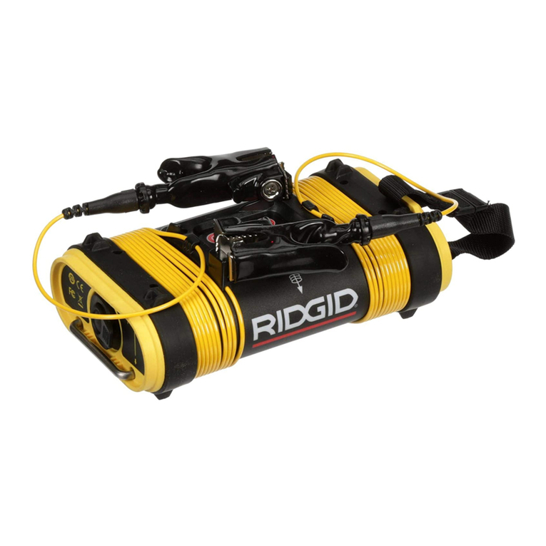
RIDGID SeekTech ST-305R User manual

ST-33QR
SeekTech
ST-305R and ST-305
WARNING!
Read this Operator’s Man-
ual carefully before using
this tool. Failure to under-
stand and follow the con-
tents of this manual may
result in electrical shock,
fire, and/or serious per-
sonal injury.
For support and additional infor-
mation about using your SeekTech
ST-305/R go to support.seesnake.
com/st305r or scan this QR code.
• Français – 19
• Español – 39
Operator’s Manual

2 – English – ST-305/R
Table of Contents
Introduction
Regulatory Statements...............................................................................................3
Safety Symbols...........................................................................................................3
General Safety Rules
Work Area Safety........................................................................................................4
Electrical Safety..........................................................................................................4
Personal Safety ..........................................................................................................4
Equipment Use and Care...........................................................................................5
Battery Use and Care.................................................................................................5
Pre-Operation Inspection
Product Overview
Description .................................................................................................................7
ST-305R Specifications ..............................................................................................7
ST-305 Specifications.................................................................................................8
Standard Equipment...................................................................................................8
Components...............................................................................................................8
Operating Instructions
ST-305/R Safety .........................................................................................................9
High Voltage Indicator.................................................................................................9
Operation Overview..................................................................................................10
Powering the ST-305/R.............................................................................................10
Keypad Overview ..................................................................................................... 11
Keypad Keys and Functions ..................................................................................... 11
Keypad Graphics and LEDs..................................................................................... 11
Cable Lead Clips ......................................................................................................12
Direct Connect Mode................................................................................................12
Inductive Clamp Mode..............................................................................................14
Inductive Mode.........................................................................................................15
Air-Coupling..............................................................................................................16
Locating....................................................................................................................17
Maintenance
Product Support .......................................................................................................17
Cleaning ...................................................................................................................17
Transport and Storage..............................................................................................17
Service and Repair...................................................................................................18
Disposal....................................................................................................................18
Battery Disposal .......................................................................................................18
*Original Instructions – English

ST-305/R – English – 3
Introduction
The warnings, cautions, and in-
structions discussed in this opera-
tor’s manual cannot cover all possi-
ble conditions and situations which
may occur. It must be understood
by the operator that common sense
and caution are factors that cannot
be built into this product, but must
be supplied by the operator.
Regulatory Statements
The EC Declaration of Conformity
(890-011-320.10) will accompany
this manual as a separate booklet
when required.
This device complies with Part 15
of FCC rules. Operation is subject
to the following two conditions:
(1) This device may not cause
harmful interference, and (2) this
device must accept any interfer-
ence received, including interfer-
ence that may cause undesired
operation.
Safety Symbols
In this operator’s manual and on the prod-
uct, safety symbols and signal words are
used to communicate important safety infor-
mation. This section is provided to improve
understanding of these signal words and
symbols.
This is the safety alert symbol. It
is used to alert you to potential
personal injury hazards. Obey all
safety messages that follow this
symbol to avoid possible injury or
death.
DANGER
DANGER indicates a hazardous situation
which, if not avoided, will result in death or
serious injury.
WARNING
WARNING indicates a hazardous situation
which, if not avoided, could result in death
or serious injury.
CAUTION
CAUTION indicates a hazardous situation
which, if not avoided, could result in minor
or moderate injury.
NOTICE
NOTICE indicates informa-
tion that relates to the pro-
tection of property.
This symbol means read the oper-
ator’s manual carefully before
using the equipment. The manual
contains important information on
the safe and proper operation of
the equipment.
This symbol means always wear
safety glasses with side shields or
goggles when handling or using
this equipment to reduce the risk
of eye injury.
This symbol indicates the risk of
electrical shock.

4 – English – ST-305/R
• Do not expose equipment to rain or wet
conditions. Water entering equipment will
increase the risk of electrical shock.
• Do not abuse the cord. Never use the
cord for carrying, pulling, or unplugging
the power tool. Keep cord away from heat,
oil, sharp edges, and moving parts. Dam-
aged or entangled cords increase the risk
of electric shock.
• If operating equipment in a damp loca-
tion is unavoidable, use a ground fault
circuit interrupter (GFCI) protected
supply. Use of a GFCI reduces the risk of
electric shock.
• Keep all electrical connections dry and
off the ground. Do not touch equipment
or plugs with wet hands to reduce the risk
of electrical shock.
Personal Safety
• Stay alert, watch what you are doing,
and use common sense when operat-
ing equipment. Do not use equipment
while you are tired or under the influence
of drugs, alcohol, or medication.A moment
of inattention while operating equipment
may result in serious personal injury.
• Use personal protective equipment.
The appropriate use of protective equip-
ment such as safety glasses, a dust mask,
non-skid safety shoes, a hard hat, high vis-
ibility clothing, and hearing protection will
reduce personal injuries.
• Do not overreach. Keep proper footing
and balance at all times.This enables bet-
ter control of the equipment in unexpected
situations.
• Dress properly. Do not wear loose cloth-
ing or jewelry. Keep your hair, clothing, and
gloves away from moving parts. Loose
clothes, jewelry, and long hair can be
caught in moving parts.
General Safety Rules
WARNING
Read all safety warnings and instruc-
tions. Failure to follow the warnings and
instructions may result in electric shock,
fire, and/or serious injury.
SAVE THESE INSTRUCTIONS!
Work Area Safety
• Keep your work area clean and well lit.
Cluttered or dark areas invite accidents.
• Do not operate equipment in explosive
atmospheres, such as in the presence
of flammable liquids, gases, or dust.
Equipment can create sparks which may
ignite the dust or fumes.
• Keep children and bystanders away
while operating equipment. Distractions
can cause you to lose control.
• Avoid traffic. Pay close attention to mov-
ing vehicles when using on or near road-
ways. Wear visible clothing or reflector
vests.
Electrical Safety
• Avoid body contact with earthed or
grounded surfaces such as pipes, radi-
ators, ranges, and refrigerators. There is
an increased risk of electrical shock if your
body is earthed or grounded.
• An improperly grounded electrical out-
let can cause electrical shock and/or
severely damage equipment. Always
check work area for a properly ground-
ed electrical outlet. Presence of a three-
prong or GFCI outlet does not ensure that
the outlet is properly grounded. If in doubt,
have the outlet inspected by a licensed
electrician.

ST-305/R – English – 5
Equipment Use and Care
• Do not force equipment. Use the correct
equipment for your application.The correct
equipment will do the job better and safer
at the rate for which it is designed.
• Do not use equipment if the power
switch does not turn it on and off. Any
equipment that cannot be controlled with
the power switch is dangerous and must
be repaired.
• Disconnect the plug from the power
source and/or the battery pack from the
equipment before making adjustments,
changing accessories, or storing. Pre-
ventive safety measures reduce the risk
of injury.
• Store idle equipment out of the reach
of children and do not allow persons
unfamiliar with the equipment or these
instructions to operate the equipment.
Equipment can be dangerous in the hands
of untrained users.
• Maintain equipment. Check for misalign-
ment or binding of moving parts, missing
parts, breakage of parts, and any other
condition that may affect the equipment’s
operation. If damaged, have the equip-
ment repaired before use. Many accidents
are caused by poorly maintained equip-
ment.
• Use the equipment and accessories
in accordance with these instructions;
taking into account the working con-
ditions and the work to be performed.
Use of the equipment for operations differ-
ent from those intended could result in a
hazardous situation.
• Use only accessories that are recom-
mended by the manufacturer for your
equipment. Accessories that may be suit-
able for one piece of equipment may be-
come hazardous when used with other
equipment.
• Keep handles dry, clean, and free from
oil and grease. This allows for better con-
trol of the equipment.
Battery Use and Care
• Use equipment only with specifically
designated battery packs. Use of any
other battery packs may create a risk of in-
jury and fire.
• Recharge only with the charger speci-
fied by the manufacturer. A charger suit-
able for one type of battery pack may cre-
ate a risk of fire when used with another
battery pack.
• Do not probe battery with conduc-
tive objects. Shorting of battery termi-
nals may cause sparks, burns, or electri-
cal shock. When the battery pack is not in
use, keep it away from other metal objects,
like paper clips, coins, keys, nails, screws
or other small metal objects that can make
a connection from one terminal to anoth-
er. Shorting the battery terminals together
may cause burns or a fire.
• Under abusive conditions, liquid may
eject from battery; avoid contact. If con-
tact occurs, flush with water. If liquid con-
tacts eyes, seek medical help. Liquid eject-
ed from the battery may cause irritation or
burns.
• Do not cover charger while in use. Prop-
er ventilation is required for correct opera-
tion. Covering charger in use could result
in fire.
• Use and store batteries and chargers
in dry, appropriate temperature areas.
Extreme temperatures and moisture can
damage batteries and result in leakage,
electrical shock, fire or burns.
• Properly dispose of batteries. Exposure
to high temperatures can cause the batter-
ies to explode; do not dispose of in a fire.
Some countries have regulations concern-
ing battery disposal. Follow all applicable
regulations.
• See the Battery and Battery Charger
Operator’s Manual for additional infor-
mation.

6 – English – ST-305/R
Pre-Operation
Inspection
WARNING
To reduce the risk of serious injury from
electrical shock or other causes, and to
prevent damage to your equipment, in-
spect all equipment and correct any
problems before each use.
To inspect all equipment, follow these steps:
1. Power off your equipment.
2. Disconnect and inspect all cords, ca-
bles, and connectors for damage or
modification.
3. Clean any dirt, oil, or other contami-
nation from your equipment to ease
inspection and to prevent it from slip-
ping from your grip during transporta-
tion or use.
4. Inspect your equipment for any bro-
ken, worn, missing, misaligned, or
binding parts, or any other condition
which might prevent safe, normal op-
eration.
5. Refer to the instructions for all other
equipment to inspect and make sure it
is in good, usable condition.
6. Check your work area for the follow-
ing:
• Adequate lighting.
• The presence of flammable liq-
uids, vapors, or dust that may ig-
nite. If present, do not work in area
until sources have been identified
and corrected. The equipment
is not explosion proof. Electrical
connections can cause sparks.
• A clear, level, stable, and dry
place for the operator. Do not use
the equipment while standing in
water.
7. Examine the job to be done and de-
termine the correct equipment for the
task.
8. Observe the work area and erect bar-
riers as necessary to keep bystanders
away.
See additional product specific safety in-
formation and warnings starting on 9.

ST-305/R – English – 7
Product Overview
Description
ST-305/R is used to refer to both the
ST-305R and the ST-305 throughout this
manual. The ST-305R and ST-305 are
functionally identical. The only differ-
ence is the ST-305R can be used with a
rechargeable battery and internal C-cell
batteries. The ST-305 is only operational
with internal C-cell batteries.
The RIDGID®SeekTech®ST-305 and ST-
305R are compact yet powerful multi-fre-
quency transmitters that can be used, in
conjunction with a RIDGID SeekTech re-
ceiver, to find buried conductors such as
pipes, cables, and wires. This allows the
line’s location to be correctly marked so it
can be exposed for repair or avoided during
excavation.
ST-305R Specifications
Weight without
batteries 1.03 kg [2.27 lb]
Dimensions
Length 198 mm [7.8 in]
Width 116 mm [4.6 in]
Height 104 mm [4.1 in]
Cable lead
length 3 m [10 ft]
Output power 0.5, 2, 5 W Nominal
Power Source
18 V Li-Ion
rechargeable
battery, six C-cell
batteries (1.5 V
alkaline or 1.2 V
NiMH or Ni-Cad
rechargeable), or
AC adapter
Current settings
Internal
batteries 25 mA – 400 mA
18V Li-Ion
battery ≤ 1,000 mA
AC adapter ≤ 1,000 mA
Default
frequencies
1 kHz, 8 kHz,
33 kHz, and 262
kHz
Operating
environment
Temperature -10°C to 50°C
[14°F to 122°F]
Storage
temperature
-20°C to 60°C
[-4°F to 140°F]
Relative
humidity 5% to 95%
Altitude 4,000 m [13,120 ft]

8 – English – ST-305/R
Components
Battery Case
Connection
Leads and
Clips Battery Shoe (ST-305R)
Grounding Stake
Inductive Clamp Jack
Battery Shoe Dust
Cover
ST-305 Specifications
Weight without
batteries 0.86 kg [1.9 lb]
Dimensions
Length 198 mm [7.8 in]
Width 116 mm [4.6 in]
Height 76 mm [3 in]
Cable lead
length 3 m [10 ft]
Output power 0.5, 2, 5 W Nominal
Power Source
Six C-cell batteries
(1.5 V alkaline or 1.2
V NiMH or Ni-Cad
rechargeable)
Current settings
Internal
batteries 25 mA – 400 mA
Default
frequencies
1 kHz, 8 kHz,
33 kHz, and 262
kHz (US) or 93 kHz
(Europe)
Operating
environment
Temperature -10°C to 50°C
[14°F to 122°F]
Storage
temperature
-20°C to 60°C
[-4°F to 140°F]
Relative
humidity 5% to 95%
Altitude 4,000 m [13,120 ft]
Standard Equipment
• ST-305R or ST-305
• Operator’s manual
• 6 C-cell batteries (Alkaline)

ST-305/R – English – 9
Operating Instructions
WARNING
This section contains important safe-
ty information that is specific to the ST-
305/R. Read these precautions carefully
before using the ST-305/R to reduce the
risk of electrical shock, fire, or other se-
rious injury.
SAVE ALL WARNINGS AND
INSTRUCTIONS FOR FUTURE
REFERENCE!
ST-305/R Safety
• Read and understand this operator’s
manual, and the instructions for any
other equipment in use and all warn-
ings before operating the ST-305/R. Fail-
ure to follow all instructions and warnings
may result in property damage and/or seri-
ous personal injury. Keep this manual with
the equipment for future use.
• Operating the equipment while in water
increases the risk of electrical shock.
Do not operate the ST-305/R if the opera-
tor or equipment are standing in water.
• The ST-305/R is not designed to pro-
vide high voltage protection and isola-
tion. Do not use where a danger of high
voltage contact is present.
• Always attach leads before turning
the ST-305/R on and always power off
the ST-305/R before disconnecting the
leads to reduce the risk of electrical
shock.
• Follow local guidelines and call before
digging. Locating equipment uses elec-
tromagnetic fields that can be distorted
and interfered with. More than one utili-
ty may be present in a given area. Follow
local guidelines and service procedures.
Confirm location of utilities before digging.
High Voltage Indicator
The ST-305/R is designed to withstand
up to 240 VAC between the two leads.
This protection is not intended to be
used continuously and excess current
may be forced through the ST-305/R. To
reduce the risk of electrical shock, do not
touch the transmitter, cords, or connec-
tions during this time. Use high voltage
precautions to disconnect the ST-305/R.
If the ST-305/R senses excess current, a
warning beep sounds and the High Voltage
LED on the keypad is lit.

10 – English – ST-305/R
Operation Overview
WARNING
Wear eye protection when appropriate
to protect your eyes against dirt and
other foreign objects. Follow operating
instructions to reduce the risk of injury
from electrical shock and other causes.
The default frequencies that come with the
ST-305/R are:
• 1 kHz [1,024 Hz]
• 8 kHz [8,192 Hz]
• 33 kHz [32,768 Hz]
• 93 kHz [93,623 Hz] or 262 kHz
[262,144 Hz]
Note: High frequency is 93kHz or 262kHz
depending on your region.
The ST-305/R has three operating modes
that can be used during a locate. Which
mode you use depends on the circumstanc-
es of the locate.
Direct Connect — The leads con-
nect directly to the target conductor
and a suitable ground.
Inductive Clamp — The optional in-
ductive clamp encircles the target
conductor when metal-to-metal con-
tact is not possible or unable to pro-
duce the desired result.
Inductive — The ST-305/R is placed
over a conductor. The internal anten-
na induces a signal on to the target
conductor.
Powering the ST-305/R
WARNING
Disconnect external leads from any en-
ergized utility before opening the bat-
tery compartment. To prevent overheat-
ing and leakage, do not mix battery types
or brands and do not combine new and
used batteries. Always remove the bat-
teries before shipping or storing the ST-
305/R.
Li-Ion 18 V Battery
A Li-Ion 18V rechargeable battery can be
used simultaneously with the internal C-cell
batteries. If the voltage falls below 15.4 V or
if the battery dies, the ST-305R switches to
internal batteries.
C-Cell Batteries
To install C-cell batteries, rotate the knob
on the battery holder counter-clockwise
until the battery compartment releases. Pull
straight back on the knob to remove the
cover. Insert the 6 batteries as shown on the
inside decals.
Note: Rechargeable C-cell batteries do not
recharge in the ST-305/R.
AC Adapter
For indoor use only, the ST-305R can also
be powered by an external AC adapter no
less than 35W. Read and follow the instruc-
tions as specified by the manufacturer of the
AC adapter before using it with the ST-305R.
Note:The AC adapter does not recharge the
18V battery.

ST-305/R – English – 11
Keypad Overview
Keypad Keys and Functions
Inductive
Mode Key
Toggle between
Inductive Mode
and Direct
Connect Mode.
Frequency
Key
Cycle through
frequency options.
Power/
Select Key
Power the unit on
or off (long press,
>3 seconds, to
power off). Cycle
through power
levels.
Keypad Graphics and LEDs
High
Voltage
Warning
On when high
voltage is
encountered.
Power/
Battery
Indicator
At start-up,
displays the
estimated
battery level.
During use,
indicates the
relative level of
output power.
Frequency
Indicator
Indicates
frequency in
use or when
expanded
frequency
settings are
active. High
frequency
is 93kHz
or 262kHz
depending on
your region.

12 – English – ST-305/R
Cable Lead Clips
The ST-305/R features cable lead clips that
can be attached mechanically or magneti-
cally. Before connecting the leads, use the
teeth on the clip to scrape off rust or paint.
When the metal is exposed you can either
clip onto the target with the teeth or use the
magnet to make the connection.
NOTICE
The cable lead clips con-
tain strong magnets. Do
not place the clips near data storage de-
vices, credit cards, or other magnetically
encoded data.
Sounds of the ST-305/R
Sounds are associated with specific events
or states. Sounds may be toggled on or
off by pressing the Frequency key and
Power key simultaneously.
Sounds of the ST-305/R
Power on 4 short beeps
Power off 3 short beeps
Inductive Clamp 2 short beeps
Inductive Mode 1 long beep,
2 short beeps
Low battery warning Rapid series of
beeps
Direct Connect Mode
Direct Connect Mode is most commonly
used when the target utility is readily acces-
sible. Do not use Direct Connect Mode on
energized (live) conductors. The transmitter
is not designed to connect to live conduc-
tors.
1. Choose connection locations for the
ground stake and the target conduc-
tor. Place the transmitter, powered off,
on the ground between these two lo-
cations.
2. Insert the ground stake into the earth
as far as possible. Wet the earth
around the ground stake to improve
grounding and to lower the resistance
of the ground. With the ST-305/R still
powered off, attach the lead clip to the
ground stake.
Instead of using the provided ground-
ing stake, the lead clip can be at-
tached to other objects such as a
shovel blade or a metal rod sunk into
the earth. Using larger grounding ob-
jects may improve grounding by in-
creasing the surface area in contact
with the earth.
Note: Always connect the lead to the
ground stake before connecting an-
other lead to the target line to direct
any current within the target conduc-
tor away from the user.

ST-305/R – English – 13
3. At the target conductor, scrape away
any dirt, paint, corrosion, or other
coatings and attach the other cable
lead clip with either the teeth or the
magnet.
Good contact between the cable lead
and the target conductor lowers the
resistance of the circuit and produces
a stronger tracing signal.
Note: Non-conductive pipes, such as
those made of clay or plastic, cannot
carry a tracing current without a trace
wire. Plastic pipes typically have a
trace wire installed with the pipe for
tracing purposes. Clip the cable lead
to the trace wire to enable tracing.
Expanded Frequency Settings
While in Direct Connect Mode, the transmit-
ter can be used with high or dual frequen-
cies.
1. Long press (>3 seconds) the Fre-
quency key to set the transmitter
to high frequency.
2. Short press the Frequency key to
cycle through dual frequency options
or return to the high frequency. Ex-
panded frequency options include:
• 262 kHz or 93 kHz only.
• 33 kHz and 1 kHz dual frequency
transmission.
• 33 kHz and 8 kHz dual frequency
transmission.
The LED associated with each fre-
quency is lit when that frequency is
in use.
3. Long press the Frequency key
again to return to standard frequency
options.
Note: High frequency is 93kHz or 262kHz
depending on your region. Expanded fre-
quency settings are only available in Direct
Connect Mode.

14 – English – ST-305/R
Inductive Clamp Mode
Read the Operator’s Manual for the Induc-
tive Clamp before using it with the ST-305/R.
It includes important safety information and
operating instructions.
Use the ST-305/R with an inductive clamp
by following these steps:
1. Before connecting the inductive
clamp, confirm that the target conduc-
tor is not live and grounded on both
ends, and that the ST-305/R is pow-
ered off.The ST-305/R is not designed
to be connected to live conductors.
2. Insert the inductive clamp plug into
the jack on the ST-305/R below the
keypad.
3. Place the jaws of the inductive clamp
around the target conductor, ensuring
that they close completely. The LEDs
on the clamp are lit when the jaws are
closed and the ST-305/R is powered
on.
4. Press the Power key . The ST-
305/R automatically switches to In-
ductive Clamp Mode and disables the
cable leads.
Note: In Inductive Clamp Mode,
the ST-305/R defaults to 50 per-
cent power level to conserve battery
power.
5. Select and set the same frequency on
both the receiver and transmitter.
6. Check the connections and adjust the
current as needed during the locate.
7. When finished, press the Power key
to power off the ST-305/R before
disconnecting the inductive clamp.

ST-305/R – English – 15
Inductive Mode
Disconnect the lead clips from any external
conductors before switching the ST-305/R
to Inductive Mode. If the lead clips are con-
nected to an external conductor and the
ST-305/R is switched to Inductive Mode, a
warning appears and operator override is
required.
Do not use clips and leads in Inductive
Mode. The ST-305/R automatically sets the
frequency to 33kHz the first time Inductive
Mode is used. After the first use, the ST-
305/R automatically uses the frequency last
used in Inductive Mode. The two frequen-
cies available in Inductive Mode are 8kHz
and 33kHz.
NOTICE
Do not place two ST-305/
Rs in Inductive Mode
with the power on within
3m [10ft] of each other.
The output of each ST-305/R can over-
load the electronics and damage one or
both units.
Use the ST-305/R in Inductive Mode by fol-
lowing these steps:
1. Place the ST-305/R so the white ori-
entation arrows located on top of the
ST-305/R are aligned with the target
conductor.
2. Press the Power key to power on
the ST-305/R. Press the Inductive
Mode key to toggle the ST-305/R
between Direct Connect Mode and In-
ductive Mode.
Ground both ends of the utility for the
best signal induction.
3. To power on and use the receiver,
refer to the receiver’s Operator Man-
ual. Ensure the frequency on the re-
ceiver matches the ST-305/R. If the
receiver signal increases when held
near the ST-305/R, it is correctly pick-
ing up the transmitted frequency.
4. After completing the locate, press the
Power key to power off the ST-
305/R.

16 – English – ST-305/R
Air-Coupling
Any transmitter in Inductive Mode gener-
ates a field through the air around it; includ-
ing the ground underneath. If within air-cou-
pling range of the ST-305/R, the receiver
will measure this field instead of the target
conductor. Air-coupling will distort readings
and misconstrue the location of the target
conductor.
Air-coupling effects can dominate the re-
ceived signal over a wide range (great-
er than 20m [70ft]) if the induced utility is
deep and poorly grounded. Very weak in-
duction and deep utilities will result in great-
er air-coupling distances. Always confirm
the detection of utilities and the readings of
depth measurements.
Air-coupling does not depend on the output
power of the transmitter and cannot be re-
duced by turning down the power. Air-cou-
pling only depends on the ratio of the field
from the transmitter compared to the in-
duced field in the target utility.
The effect of air-coupling can vary continu-
ously so be aware of the difference between
the transmitter’s field and the induced field
of the utility being traced. While both will
have the same frequency, the transmitter’s
field is only strong enough to obscure the
utility’s signal in the region around the trans-
mitter itself.
Be sure to look overhead for power lines
that could also confuse the locate.
Testing for Air-Coupling
To test for air-coupling, tilt the receiver at a
45 degree angle towards the ST-305/R and
ensure the lower antenna of the receiver
touches the ground. Afterwards, tilt the re-
ceiver 45 degrees away from the ST-305/R
and observe the depth reading. If the depth
reading changes significantly, air-coupling
may be affecting the accuracy of the locate.
Alternatively, test for air-coupling by stand-
ing 6m [20ft] away from the ST-305/R. With
the lower antenna on the ground, take note
of the indicated depth measurement on the
receiver. Raise the receiver vertically 45cm
[18in] and observe the change in the depth
indication. If the receiver only reads the con-
ductor, the depth should increase accord-
ingly. If the receiver is air-coupling, the depth
indication does not change by 45cm [18in],
but changes disproportionately.

ST-305/R – English – 17
Locating
WARNING
To reduce the risk of electrical shock,
power off the ST-305/R before discon-
necting the leads and remove the lead
from the target conductor before remov-
ing the lead from the ground stake.
Note:When the ST-305/R is powered on and
in Direct Connect Mode,only hold the cable
leads by the plastic sheathing. Do not touch
the metal scraper tip, teeth, or magnet.
1. With one cable lead attached to the
ground stake and the other attached to
the target conductor, press the Power
key to power on the ST-305/R.
Upon start up, the ST-305/R mea-
sures the current flowing through the
target conductor and beeps to indicate
output. Faster beeps indicate a higher
output current.
2. Select a frequency by pressing the
Frequency key until the desired
frequency is selected. Long press (>3
seconds) the Frequency key to se-
lect the expanded frequency option for
dual or high frequencies.
3. Follow the instructions in the receiv-
er’s Operator’s Manual to power on
and use the receiver. Ensure the fre-
quency on the receiver matches the
ST-305/R. If the receiver signal in-
creases when held near the ST-305/R,
it is correctly picking up the transmit-
ted frequency.
4. After completing the locate, press the
Power key to power off the ST-
305/R.
Maintenance
Product Support
For support and additional information
about using your ST-305/R, visit support.
seesnake.com/st305r.
Cleaning
WARNING
Disconnect all cords and cables and re-
move batteries prior to cleaning the ST-
305/R to reduce the risk of electrical
shock.
Do not use liquid or abrasive cleaners on the
ST-305/R. Clean the ST-305/R with damp
cloth. Do not allow any liquid to enter the ST-
305/R.
Transport and Storage
• Store in a locked area out of the reach
of children and people unfamiliar with
its purpose.
• Store in a dry place to reduce risk of
electrical shock.
• Store away from heat sources such as
radiators, heat registers, stoves, and
other products (including amplifiers)
that produce heat.
• Storage temperature should be -20°C
to 60°C [-4°F to 140°F].
• Do not expose to heavy shocks or im-
pacts during transport.
• Remove the battery before shipping
and before storing for extended peri-
ods of time.

18 – English – ST-305/R
Service and Repair
WARNING
Improper service or repair can cause the
ST-305/R to be unsafe to operate.
Service and repair of the ST-305/R must be
performed at a RIDGID Independent Autho-
rized Service Center. To maintain the safe-
ty of the tool, make sure a qualified repair
person services your equipment using only
identical replacement parts. Discontinue
using the ST-305/R, remove the batteries,
and contact service personnel under any of
the following conditions:
• The equipment does not operate nor-
mally when operating instructions are
followed.
• The equipment exhibits a distinct
change in performance.
• The equipment has been dropped or
damaged.
• Liquid has been spilled or objects have
fallen into the equipment.
For information on your nearest RIDGID In-
dependent Service Center or any service or
repair questions:
• Contact your local RIDGID distributor.
• Go to www.RIDGID.com.
• Contact Ridge Tool Company
Technical Service Department at
the U.S. and Canada, call 1-800-519-
3456.
Disposal
Parts of the unit contain valu-
able materials that can be re-
cycled. There are companies
that specialize in recycling that
may be found locally. Dispose
of the components in compliance with all ap-
plicable regulations. Contact your local
waste management authority for more infor-
mation.
For EC countries: Do not dispose of electri-
cal equipment with household waste!
According to the European Guideline
2012/19/EU for Waste Electrical and Elec-
tronic Equipment and its implementation
into national legislation, electrical equip-
ment that is no longer usable must be col-
lected separately and disposed of in an en-
vironmentally-correct manner.
Battery Disposal
For EC countries: Defective or used bat-
tery packs/batteries must be recycled ac-
cording to the guideline 2006/66/EC.

ST-33QR
SeekTech
ST-305R et ST-305
AVERTISSEMENT !
Lire soigneusement ce Ma-
nuel de l'opérateur avant
d'utiliser cet appareil. Un
manque de compréhension
et un manque de respect
du contenu de ce manuel
peuvent causer un choc
électrique, un incendie et/ou
des blessures graves.
Pour obtenir de l'aide et plus d’in-
formations à propos de l'utilisation
de votre ST-305/R, veuillez visiter
support.seesnake.com/fr/st305r
ou scannez ce code QR.
Manuel de l'opérateur

20 – Français – ST-305/R
Introduction
Énoncés réglementaires...........................................................................................21
Règles générales de sécurité
Sécurité du lieu de travail .........................................................................................22
Sécurité électrique....................................................................................................22
Sécurité personnelle.................................................................................................22
Utilisation et entretien du matériel............................................................................23
Utilisation et entretien des piles................................................................................23
Contrôle préalable
Vue d'ensemble de ST-305/R
Description ...............................................................................................................25
Caractéristiques du ST-305R....................................................................................26
Caractéristiques du ST-305 ......................................................................................26
Équipement standard ...............................................................................................26
Composantes ...........................................................................................................27
Informations de sécurité spécifiques
Sécurité du ST-305/R ...............................................................................................27
Indicateur de haute tension......................................................................................28
Consignes d'utilisation
Mise sous tension du ST-305/R................................................................................29
Vue d’ensemble du pavé numérique........................................................................29
Touches et fonctions du pavé numérique.................................................................29
Graphique de pavé numérique et LED.....................................................................30
Pinces de câbles ......................................................................................................30
Mode Connexion directe...........................................................................................31
Mode Pince inductive ...............................................................................................33
Mode Inductif............................................................................................................34
Couplage d'air ..........................................................................................................35
Localisation ..............................................................................................................36
Maintenance et assistance
Assistance................................................................................................................36
Nettoyage .................................................................................................................36
Transport et stockage ...............................................................................................36
Service et réparation ................................................................................................37
Mise au rebut............................................................................................................37
Mise au rebut des piles ............................................................................................37
Table des matières
*Traduction de la notice originale – Français
This manual suits for next models
1
Table of contents
Languages:
Other RIDGID Transmitter manuals

RIDGID
RIDGID SeekTech ST-510 User manual

RIDGID
RIDGID SeekTech ST-33Q User manual

RIDGID
RIDGID NAVITRACK User manual

RIDGID
RIDGID SeekTech ST-305 User manual

RIDGID
RIDGID SeekTech ST-305 User manual

RIDGID
RIDGID NAVITRACK User manual

RIDGID
RIDGID SeeSnake Max rM200 User manual

RIDGID
RIDGID NaviTrack 10 User manual

RIDGID
RIDGID NAVITRACK User manual

RIDGID
RIDGID SeekTech ST-305 User manual