RIDGID NAVITRACK User manual

NaviTrack®10 Watt
Pipe and Cable Line Transmitter
Original Instructions – English – 1
WARNING!
Read this Operator’s Man-
ual carefully before using
this tool. Failure to under-
stand and follow the con-
tents of this manual may
result in electrical shock,
fire and/or serious person-
al injury.
NaviTrack Line Transmitter
Record product serial number below as it appears on the nameplate.
Serial
No.
Operator’s Manual

2 – English
TM
Table of Contents
Recording Form for Machine Serial Number ����������������������������������������������������������������������������������������������������������������������������� 1
Safety Symbols����������������������������������������������������������������������������������������������������������������������������������������������������������������������������������3
General Safety Rules
Work Area Safety����������������������������������������������������������������������������������������������������������������������������������������������������������3
Electrical Safety������������������������������������������������������������������������������������������������������������������������������������������������������������3
Personal Safety�������������������������������������������������������������������������������������������������������������������������������������������������������������3
Equipment Use and Care ���������������������������������������������������������������������������������������������������������������������������������������������3
Service �������������������������������������������������������������������������������������������������������������������������������������������������������������������������4
Specific Safety Information
NaviTrack Line Transmitter Safety���������������������������������������������������������������������������������������������������������������������������������4
Description, Specifications, and Standard Equipment
Description �������������������������������������������������������������������������������������������������������������������������������������������������������������������5
Specifications ���������������������������������������������������������������������������������������������������������������������������������������������������������������5
Standard Equipment�����������������������������������������������������������������������������������������������������������������������������������������������������5
Components ��������������������������������������������������������������������������������������������������������������������������������������������������������������������5
Icon Legend ���������������������������������������������������������������������������������������������������������������������������������������������������������������������6
Pre-Operation Inspection������������������������������������������������������������������������������������������������������������������������������������������������6
Work Area and Equipment Set Up
High Voltage Warning ��������������������������������������������������������������������������������������������������������������������������������������������������� 7
Powering the NaviTrack Line Transmitter ���������������������������������������������������������������������������������������������������������������������� 7
Operating Instructions
Direct Connect Mode����������������������������������������������������������������������������������������������������������������������������������������������������8
Inductive Clamp Mode������������������������������������������������������������������������������������������������������������������������������������������������ 10
Inductive Mode �����������������������������������������������������������������������������������������������������������������������������������������������������������10
Air‑Coupling �����������������������������������������������������������������������������������������������������������������������������������������������������������������11
Variable Power Current����������������������������������������������������������������������������������������������������������������������������������������������� 12
Helpful Hints ������������������������������������������������������������������������������������������������������������������������������������������������������������������ 12
Cleaning �������������������������������������������������������������������������������������������������������������������������������������������������������������������������13
Accessories��������������������������������������������������������������������������������������������������������������������������������������������������������������������13
Transport and Storage ��������������������������������������������������������������������������������������������������������������������������������������������������13
Service and Repair �������������������������������������������������������������������������������������������������������������������������������������������������������� 13
Disposal �������������������������������������������������������������������������������������������������������������������������������������������������������������������������13
Troubleshooting������������������������������������������������������������������������������������������������������������������������������������������������������������� 14
Lifetime Warranty ����������������������������������������������������������������������������������������������������������������������������������������������������������������������������16

English – 3
TM
General Safety Rules
WARNING
Read all safety warnings and instructions. Failure to follow
the warnings and instructions may result in electric shock,
re, and/or serious injury.
SAVE THESE INSTRUCTIONS!
Work Area Safety
• Keep your work area clean and well lit. Cluttered or
dark areas invite accidents�
• Do not operate equipment in explosive atmospheres,
such as in the presence of flammable liquids, gases,
or dust. Equipment can create sparks which may ignite
the dust or fumes�
• Keep children and bystanders away while operating
equipment. Distractions can cause you to lose control�
Electrical Safety
• Avoid body contact with earthed or grounded sur-
faces such as pipes, radiators, ranges, and refrigera-
tors. There is an increased risk of electrical shock if your
body is earthed or grounded�
• Do not expose equipment to rain or wet conditions.
Water entering equipment will increase the risk of elec‑
trical shock�
• Do not abuse the cord. Never use the cord for carrying,
pulling, or unplugging the power tool� Keep cord away
from heat, oil, sharp edges, and moving parts� Damaged
or entangled cords increase the risk of electric shock�
• If operating equipment in a damp location is unavoid-
able, use a ground fault circuit interrupter (GFCI)
protected supply. Use of a GFCI reduces the risk of
electric shock�
• Keep all electrical connections dry and off the
ground. Do not touch equipment or plugs with wet
hands to reduce the risk of electrical shock�
Personal Safety
• Stay alert, watch what you are doing, and use com-
mon sense when operating equipment. Do not use
equipment while you are tired or under the influence of
drugs, alcohol, or medication� A moment of inattention
while operating equipment may result in serious person‑
al injury�
• Use personal protective equipment. Always wear eye
protection� The appropriate use of protective equipment
such as a dust mask, non‑skid safety shoes, a hard hat,
and hearing protection will reduce personal injuries�
• Do not overreach. Keep proper footing and balance at
all times� This enables better control of the equipment in
unexpected situations�
• Dress properly. Do not wear loose clothing or jewel‑
ry� Keep your hair, clothing, and gloves away from mov‑
ing parts� Loose clothes, jewelry, and long hair can be
caught in moving parts�
Equipment Use and Care
• Do not force equipment. Use the correct equipment for
your application� The correct equipment will do the job
better and safer at the rate for which it is designed�
• Do not use equipment if the power switch does not
turn it ON and OFF. Any equipment that cannot be con‑
trolled with the power switch is dangerous and must be
repaired�
Safety Symbols
In this operator’s manual and on the product, safety symbols and signal words are used to communicate important safety
information� This section is provided to improve understanding of these signal words and symbols�
This is the safety alert symbol� It is used to alert you to potential personal injury hazards� Obey all safety messages that follow
this symbol to avoid possible injury or death�
DANGER DANGER indicates a hazardous situation which, if not avoided, will result in death or serious injury�
WARNING WARNING indicates a hazardous situation which, if not avoided, could result in death or serious injury�
CAUTION CAUTION indicates a hazardous situation which, if not avoided, could result in minor or moderate injury�
NOTICE
NOTICE indicates information that relates to the protection of property�
This symbol means read the operator’s manual carefully before using the equipment�The operator’s manual contains important
information on the safe and proper operation of the equipment�
This symbol means always wear safety glasses with side shields or goggles when handling or using this equipment to reduce
the risk of eye injury�
This symbol indicates the risk of electrical shock�

4 – English
TM
• Disconnect the plug from the power source and/or
the battery pack from the equipment before making
adjustments, changing accessories, or storing. Pre‑
ventive safety measures reduce the risk of injury�
• Store idle equipment out of the reach of children and
do not allow persons unfamiliar with the equipment
or these instructions to operate the equipment. Equip‑
ment can be dangerous in the hands of untrained users�
• Maintain equipment. Check for misalignment or bind‑
ing of moving parts, missing parts, breakage of parts,
and any other condition that may affect the equipment’s
operation� If damaged, have the equipment repaired
before use� Many accidents are caused by poorly main‑
tained equipment�
• Use the equipment and accessories in accordance
with these instructions; taking into account the
working conditions and the work to be performed.
Use of the equipment for operations different from those
intended could result in a hazardous situation�
• Use only accessories that are recommended by the
manufacturer for your equipment. Accessories that
may be suitable for one piece of equipment may become
hazardous when used with other equipment�
• Keep handles dry, clean, and free from oil and grease.
This allows for better control of the equipment�
Service
Ensure a qualified repair person services your equipment
using only identical replacement parts to maintain the safety
of the tool� Remove the batteries and refer servicing to quali‑
fied service personnel under any of the following conditions:
• If liquid has been spilled or objects have fallen into
product�
• If the product does not operate normally when follow‑
ing the operating instructions�
• If the product has been dropped or damaged�
• When the product exhibits a distinct change in per‑
formance�
Specic Safety Information
WARNING
This section contains important safety information that
is specic to the NaviTrack Line Transmitter. Read these
precautions carefully before using the NaviTrack Line
Transmitter to reduce the risk of electrical shock, re, or
other serious personal injury.
SAVE ALL WARNINGS AND INSTRUCTIONS
FOR FUTURE REFERENCE!
Keep this manual with the equipment for use by the operator�
NaviTrack Line Transmitter Safety
• An improperly grounded electrical outlet can cause
electrical shock and/or severely damage equipment.
Always check work area for a properly grounded electri‑
cal outlet� Presence of a three‑prong or GFCI outlet does
not ensure that the outlet is properly grounded� If in doubt,
have the outlet inspected by a licensed electrician�
• Do not operate this equipment if operator or NaviT-
rack Line Transmitter is standing in water. Operating
the NaviTrack Line Transmitter while in water increases
the risk of electrical shock�
• Do not use where a danger of high voltage contact
is present. Do not attach leads to high voltage lines�The
equipment is not designed to provide high voltage pro‑
tection and isolation� Use high voltage precautions when
disconnecting the leads�
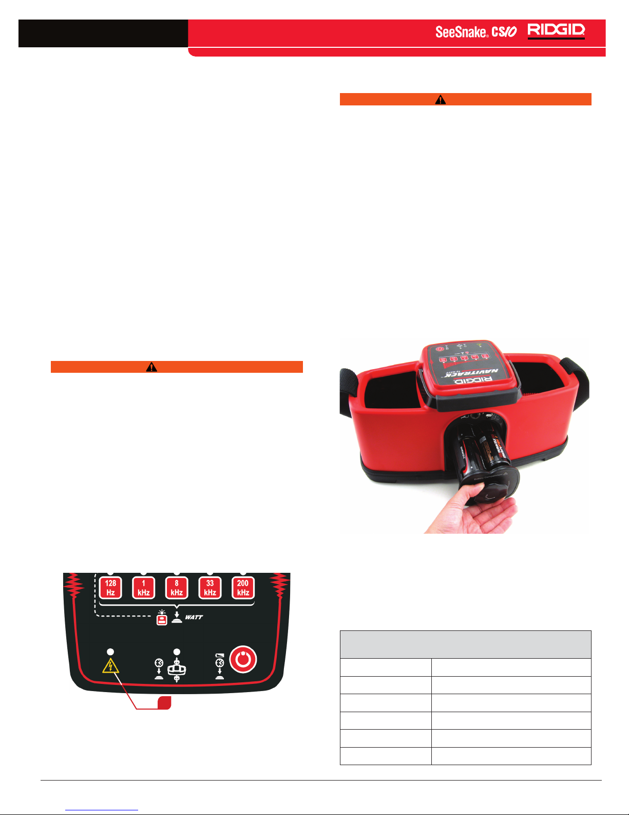
• Always attach leads before turning ON the NaviT-
rack Line Transmitter and always turn OFF the Navi-
Track Line Transmitter before disconnecting leads to
reduce the risk of electrical shock.
• Follow local guidelines and call before digging.
Locating equipment uses electromagnetic fields that
can be distorted and interfered with� More than one util‑
ity may be present in a given area� Follow local guide‑
lines and service procedures� Confirm location of utilities
before digging�
• Read and understand this operator’s manual, and
the instructions for any other equipment in use and
all warnings before operating the NaviTrack Line
Transmitter. Failure to follow all instructions and warn‑
ings may result in property damage and/or serious per‑
sonal injury�
The information supplied with this product cannot
cover all possible conditions and situations that
may occur, and should be used in conjunction with
appropriate training, sound judgment, and good
work practices.These factors cannot be built into the
product, but must be supplied by the operator.
The EC Declaration of Conformity (890‑011‑320�10) will
accompany this manual as a separate booklet when
required�

English – 5
TM
Description, Specications, and
Standard Equipment
Description
The NaviTrack Line Transmitter is part of the NaviTrack
cable and pipe locating system� It can be used to energize a
pipe or line so that the magnetic fields emitted by the under‑
ground line can be traced� Use the NaviTrack Line Trans‑
mitter in conjunction with a RIDGID‑SeekTech locator or a
NaviTrack locator to find buried conductors such as pipes,
cables, and wires�
The NaviTrack Line Transmitter can apply an active tracing
signal to target a conductor using the following three modes:
• Direct Connect — The leads on the NaviTrack Line
Transmitter connect directly to the target conductor
and a suitable ground�
• Inductive Clamp — The optional inductive clamp
encircles the target conductor which eliminates
metal‑to‑metal contact�
• Inductive — The NaviTrack Line Transmitter is
placed above and in‑line with a conductor� The
internal antenna induces a signal to locate the tar‑
get conductor�
Specications
Table 1
NaviTrack Line Transmitter Specifications
Weight without batteries 4�75 lb [2�15 kg]
Dimensions:
Depth 7�0 in [17�7 cm]
Width 15�0 in [38�1 cm]
Height 6�5 in [16�5 cm]
Cable coil length 3 ft — 25 ft [1�0 m — 7�6 m]
External power adapter
output power 1 W — 10 W
Batteries 8 D‑cell batteries
Power settings 4 mA, 15 mA, 50 mA
150 mA, 600 mA
Operating Environment:
Temperature –40°F — 140°F
[–40°C — 60°C]
Storage temperature –40°F — 140°F
[–40°C — 60°C]
Humidity 5% — 95% RH
Altitude 6,562 ft [2,000 m]
Standard Equipment
• NaviTrack Line Transmitter
• Operator’s Manual
• Direct connect leads and clips
• 8 Alkaline D‑cell batteries
NOTE: The NaviTrack Line Transmitter complies with Part
15 of FCC rules in accordance with the following: Operation
must not cause harmful interference and this device must
accept any interference received, including interference
that may cause undesired operation.
Components
Figure 1 – Top View
Figure 2 – Bottom View
Shoulder Strap
Magnetic Lead Clip
Cable Lead
Keypad
Handle
Pocket
Security Cable Holes Grounding Stake
Serial Number Label

6 – English
TM
Figure 3 – Back View
Icon Legend
Table 2
NaviTrack Line Transmitter Icons
Icon Definition
High Voltage Present
WATT
Variable Current Power ‑ (See section
on Variable Current Power in this Oper-
ator’s Manual for more information)
Battery Status ‑ Hold Power Key down
for two seconds to check battery status
Inductive Mode ‑ Press frequency key
for two seconds to turn ON
Power ON and OFF
Caution
Inductive Clamp
30W
12-15V
External Power 12 – 15 VDC
Pre-Operation Inspection
WARNING
Before each use, inspect the NaviTrack Line Transmitter
and correct any problems to reduce the risk of serious
injury from electrical shock or other causes and prevent
machine damage.
1� Confirm that the power is OFF, that leads and any exter‑
nal power and cords are disconnected, and that the bat‑
tery is removed� Inspect the cords, cables, and connec‑
tors for damage or modification�
2� Clean any dirt, oil, or other contamination from the Navi‑
Track Line Transmitter to aid in inspection and to pre‑
vent the unit from slipping from your grip during trans‑
port or use�
3� Inspect the NaviTrack Line Transmitter for any broken,
worn, missing, misaligned or binding parts, or any other
condition which might prevent safe, normal operation�
4� Inspect any other equipment being used per its instruc‑
tions to make sure it is in good, usable condition�
5� If any problems are found, do not use the equipment
until the problems are corrected�
Work Area and Equipment Set Up
WARNING
Set up the NaviTrack Line Transmitter and work area in
accordance with these procedures to reduce the risk of
injury from electrical shock, re, and other causes and to
prevent damage to the NaviTrack Line Transmitter.
1� Check work area for the following:
• Adequate lighting�
• Flammable liquids, vapors, or dust that may ignite�
If present, do not work in area until sources have
been identified and corrected� The NaviTrack Line
Transmitter is not explosion proof� Electrical con‑
nections can cause sparks�
• Clear, level, stable, dry place for operator�
• Clear path to electrical outlet that does not con‑
tain any potential sources of damage for the power
cord when using external power�
DC Power Jack
Jack for Inductive Clamp
Battery Compartment

English – 7
TM
2� Determine the correct equipment for the application� The
NaviTrack Line Transmitter is made to locate conductors
underground�
3� Inspect the line to have a signal applied to it� The line
must be metal to allow the NaviTrack Line Transmitter
to locate it� If using the transmitter on insulated conduc‑
tors, ground the target conductor at each end to ensure
that the signal will be strong enough to locate� The Navi‑
Track Line Transmitter is not designed to provide high
voltage insulation or protection� Do not use where a
danger of high voltage contact is present�
4� Determine the presence of chemicals� If chemicals are
present, it is important to understand the specific safety
measures required to work around the chemicals� Con‑
tact the chemical manufacturer for required information�
5� Make sure all equipment has been properly inspected�
6� Evaluate the work area and determine if any barriers
are needed to keep bystanders away� Bystanders can
distract the operator during use� If working near traffic,
erect cones or other barriers to alert drivers�
High Voltage Warning
WARNING
The NaviTrack Line Transmitter is designed to withstand
up to 240 VAC 50/60 Hz between the two leads. This
protection is not intended to be used continuously. If the
NaviTrack Line Transmitter indicates the presence of high
voltage, use high voltage precautions to disconnect the
NaviTrack Line Transmitter. To reduce the risk of electri-
cal shock, do not touch the transmitter, cords, or connec-
tions during this time. Do not deliberately connect to the
live power lines.
The voltage on an energized line can cause excess current
to be forced through the NaviTrack Line Transmitter� When
the NaviTrack Line Transmitter encounters voltage greater
than 90 V, the high voltage warning LED will flash red (See
Item1, Figure4) If the high voltage LED begins flashing, fol‑
low high voltage safety procedures to disconnect the trans‑
mitter�
1
Figure 4 – High Voltage LED
Powering the NaviTrack Line Transmitter
WARNING
Disconnect external leads from any energized utility
before opening the battery compartment. To prevent over-
heating and leakage, do not mix battery types or used and
new batteries. Always remove the batteries before ship-
ping the NaviTrack Line Transmitter.
Battery Power
Install batteries in the NaviTrack Line Transmitter in accor‑
dance with the following:
1� Turn the knob on the battery holder counterclockwise
(See Figure 5)�
2� When the battery holder carriage springs out slightly,
pull straight back on the knob to slide out�
3� Insert eight D‑cell batteries as shown on the inside
decal�
4� Fit the carriage into the case and turn the knob clock‑
wise while lightly pushing in to close�
Figure 5 – Inserting Battery Carriage
Eight new alkaline D‑cell batteries will power the NaviTrack
Line Transmitter for approximately 12�5 hours� Battery oper‑
ation time will vary with battery rating and use� See Table
3 for estimated operating times with an assumed nominal
load of 150 ohms�
Table 3
Estimated Operating Times
Current Estimated Operating Time
400 mA 1�8 hours
200 mA 3�6 hours
100 mA 7�25 hours
50 mA 14 hours
25 mA 28 hours

8 – English
TM
Battery Level Indicator
To check the battery level, turn ON the NaviTrack Line Trans‑
mitter, hold down the Power Key until all the LEDs light
up, and then release the Power Key �The number of LEDs
flashing, from left to right, will indicate the battery level� Refer
to the bar graph above the LEDs�
Auto Shutdown
At low power, by default, the NaviTrack Line Transmitter will
automatically shutdown if a key has not been pressed for 4
hours� At high power, by default, the NaviTrack Line Trans‑
mitter will automatically shutdown if a key has not been
pressed for 1 hour�
Rapidly press the Power Key twice to toggle the auto shut‑
down feature ON or OFF� The frequency LED lights will run
up, left to right, when Auto Shutdown feature is ON� The fre‑
quency LED lights will run down, right to left, when the Auto
Shutdown feature is OFF�
Alternate Power Supply
The NaviTrack Line Transmitter can be powered with an
external 10 – 28 VDC power source with a supply no less
than 35 W� If using an adapter, read and follow the instruc‑
tions as specified by the manufacturer� To prevent electri‑
cal shock and damage, ensure the external power source
is fully isolated from the ground and power mains� Do not
use a non‑isolated power supply with the NaviTrack Line
Transmitter�
Ensure the adapter cord has a clear, dry path and does not
contain any potential source of damage� Use dry hands to
plug in the cords�
NOTICE
Do not power the NaviTrack Line Transmit-
ter with a vehicle 12 VDC cigarette lighter connection to
prevent damage to the NaviTrack Line Transmitter and
to avoid contact with potentially lethal voltage.
Operating Instructions
WARNING
Always wear eye protection to protect your eyes against
dirt and other foreign objects. Follow operating instruc-
tions to reduce the risk of injury from electrical shock and
other causes.
Direct Connect Mode
Direct Connect Mode is most commonly used when the tar‑
get utility is readily accessible� Do not use Direct Connect
Mode on energized conductors�
Use the NaviTrack Line Transmitter in Direct Connect Mode
by performing the following steps:
1� Ensure that the target conductor is not live� The Navi‑
Track Line Transmitter is not designed to connect to live
conductors�
2� Choose connection locations for the ground stake and
the target conductor� Each cable lead will extend up to
25 ft [7�6 m]� The farther the leads are extended, the far‑
ther the receiver should be used from the transmitter to
avoid confusing the signal coupled onto the target con‑
nector with the signal from the cable leads� If perform‑
ing a locate close to the transmitter, keep the leads as
short as possible and store excess lead cable in the
side pockets of the transmitter�
3� Remove the ground stake from the bottom of the Navi‑
Track Line Transmitter and insert it into the earth� To
enable a good ground, insert the ground stake as far
as possible into the earth� If desired, wet the earth
around the ground stake to improve grounding and to
lower the resistance of the ground�
4� With the NaviTrack Line Transmitter powered OFF,
attach the lead clip to the ground stake (See Figure6)�
Alternatively, attach the cable lead to other things like a
shovel blade or a larger rod sunk into the earth� Using
other grounding equipment may also improve ground‑
ing by increasing the area in contact with the earth�
Figure 6 – Cable Lead attached to a Ground Stake
5� Connect the other cable lead to the target conductor
(See Figure 7, Figure 8 and Figure 9)� Non‑conduc‑
tive pipes, such as those made of clay or plastic, can‑
not carry a tracing current without a trace wire� Plastic
pipes typically have a trace wire installed with the pipe
for tracing purposes� Clip the cable lead to the trace
wire to enable tracing�

English – 9
TM
NOTE: Scrape away any dirt, paint, corrosion, or other
coatings on the target conductor to ensure good contact
with the cable lead, to lower the resistance of the circuit,
and to produce a stronger tracing signal.
Figure 7 – Connecting the Cable Lead to the Target
Conductor
Figure 8 – Alternative connection method
Figure 9 – Using the magnet embedded in the
Cable Lead to connect to the target
NOTE: Always connect the lead to the ground stake before
connecting another lead to the target line to direct any
current within the target conductor away from the user.
6� After attaching both leads, press the Power Key to
turn ON the NaviTrack Line Transmitter� After powering
ON, the NaviTrack Line Transmitter will emit ascending
beeps and then pause to measure the current flowing
through the target conductor� Faster beeps will indicate
a higher detected current�
7� Select one of the following frequencies:
• 128 Hz low
• 1 kHz low
• 8 kHz medium
• 33 kHz medium
• 262 kHz (93 kHz Europe) high
• 200 kHz alternate high frequency� To set the 200
kHz frequency, press the 262 kHz high frequency
button for ten seconds� The LED will blink rapidly
three times when set� The 262 kHz LED will blink
every 5 seconds to indicate that the NaviTrack Line
Transmitter is operating on the alternate 200 kHz
frequency�
8� Check the circuit� More current will give a stronger sig‑
nal� Signal strength measured by the receiver is directly
proportional to the amount of current on the line� More
current means a stronger signal will be received by the
receiver�
NOTE: To prolong battery life and to reduce the chance
of the signal “bleeding over” onto adjacent lines, use the
least amount of current needed to get a clear reading on
the receiver.
9� Turn on the receiver and follow the instructions speci‑
fied in the operator’s manual� Ensure the frequency on
the receiver matches the NaviTrack Line Transmitter� If
the receiver signal increases when the receiver is held
near the NaviTrack Line Transmitter, it is correctly pick‑
ing up the transmitted frequency�
10� After completing the locate, press the Power Key to
turn OFF the NaviTrack Line Transmitter� To reduce the
risk of electrical shock, turn OFF the unit before dis‑
connecting the leads and remove the lead from the tar‑
get conductor before disconnecting the lead from the
ground stake�
NOTE: When the NaviTrack Line Transmitter is ON and
in Direct Connect Mode do not come in contact with the
scraper tip and only hold leads by their plastic sheathing.

10 – English
TM
Checking the Receiver
To ensure that the NaviTrack Line Transmitter and the receiv‑
er are set to the same frequency, hold the receiver near the
NaviTrack Line Transmitter cables and confirm that the sig‑
nal is being received (See Figure 10)�
Figure 10 – Checking the Receiver
Inductive Clamp Mode
The Inductive Clamp allows you to induce a traceable cur‑
rent onto a pipe or cable where the Direct Connect leads
cannot clip�
NOTE: The Inductive Clamp is not recommended for use
with frequencies less than 8 kHz.
Figure 11 – Inductive Clamp
Use the NaviTrack Line Transmitter with an inductive clamp
by performing the following steps:
1� Confirm that the target conductor is not live� The Navi‑
Track Line Transmitter is not designed to be connected
to live conductors�
2� Make sure the NaviTrack Line Transmitter is turned
OFF� Do not turn ON the NaviTrack Line Transmitter
until the inductive clamp has been attached�
3� Insert the inductive clamp plug into the port on the
NaviTrack Line Transmitter located in the back of the
unit� After plugging in the inductive clamp, the Navi‑
Track Line Transmitter will disable the coil cords�
4� Place the jaws of the inductive clamp around the tar‑
get conductor� Ensure the jaws of the inductive clamp
close completely�
5� Press the Power Key to turn ON the NaviTrack Line
Transmitter and select a frequency for locating� Check
the circuit and adjust the current� Ensure the receiver
and the NaviTrack Line Transmitter are set to the same
frequency�
6� After completing the locate, press the Power Key to
turn OFF the NaviTrack Line Transmitter before discon‑
necting the inductive clamp�
NOTE: It is not necessary to separately ground the trans-
mitter when using the Inductive Clamp. However, the line
onto which the current is induced must be grounded in
both directions for a signal to be induced away from the
transmitter.
Inductive Mode
The NaviTrack Line Transmitter can be used with a direct
connection to a pipe or a cable� In Inductive Mode the Navi‑
Track Line Transmitter generates a field which induces a
current onto a conductor�
Disconnect the lead clips from any external conductors
before switching the NaviTrack Line Transmitter to Inductive
Mode�
To use the NaviTrack Line Transmitter in Inductive Mode,
perform the following steps:
1� Place the NaviTrack Line Transmitter so the orientation
mark located on top of the NaviTrack Line Transmitter
aligns with the target conductor�
2� Place the NaviTrack Line Transmitter over the line to be
traced (See Figure 12)�
Figure 12 – Inductive Mode Alignment

English – 11
TM
3� If required, rotate the NaviTrack Line Transmitter on the
conductor’s axis to help reduce the chance of air cou‑
pling (See Figure 13)�
Figure 13 – Rotating the NaviTrack Line Transmitter
on the Conductor’s Axis
4� Press the Power Key to turn ON the NaviTrack Line
Transmitter�
5� Select a frequency� After selecting a frequency, press
and hold the same frequency button a second time for
two seconds� The Induction LED and the selected fre‑
quency LED will turn ON to show that the NaviTrack
Line Transmitter is transmitting inductively on the spec‑
ified frequency (See Item 1, Figure 14). The NaviTrack
Line Transmitter will emit group tones instead of single
tones in Inductive Mode�
1
Figure 14 – Induction LED
NOTE: Frequencies lower than 8 kHz couple poorly induc-
tively. When using Inductive Mode, use higher frequencies
to obtain a better signal at the receiver.
Sounds in Inductive Mode
The NaviTrack Line Transmitter emits two beeps when shift‑
ing into Inductive Mode� When operating in Inductive Mode,
the NaviTrack Line Transmitter emits a series of intermittent
four‑tone beeps�
Air-Coupling
In Inductive Mode, the NaviTrack Line Transmitter will gen‑
erate a field through the air around it; including the ground
underneath� If within air‑coupling range of the NaviTrack
Line Transmitter, the receiver will measure this field instead
of the target conductor� Air‑coupling may distort readings
and misconstrue the location of the target conductor�
Air‑coupling can occur over a wide range; greater than 70ft
[20 m] if the induced utility is deep and poorly grounded�
Very weak induction and deep utilities will result in greater
air‑coupling distances� Always confirm the detection of utili‑
ties and the readings of depth measurements�
Air‑coupling does not depend on the output power of the
transmitter and cannot be reduced by turning down the
power� Air‑coupling only depends on the ratio of the field
from the transmitter compared to the induced field in the
target utility�
Note that air‑coupling can vary continuously� Be aware
of the difference between the transmitter’s field and the
induced field of the utility being traced� While both will have
the same frequency, the transmitter’s field is limited to the
region around the transmitter itself� Be sure to look over‑
head for power lines that could also confuse the locate�
Testing for Air-Coupling
To test for air‑coupling, tilt the receiver at a 45 degree
angle towards the NaviTrack Line Transmitter and ensure
the lower antenna of the locator touches the ground� After‑
wards, tilt the receiver 45 degrees away from the NaviTrack
Line Transmitter and observe the depth reading� If the depth
reading changes significantly, air‑coupling may be occurring�
Alternatively, test for air‑coupling by standing 20 ft [6 m]
away from the NaviTrack Line Transmitter� With the lower
antenna on the ground, take note of the indicated depth
measurement on the locator� Raise the locator vertically
18in [45cm] and observe the change in the depth indication�
If the locator only reads the conductor, the depth should
increase accordingly� If the locator is air‑coupling, the depth
indication will not change by 18in [45cm], but will change
disproportionately�

12 – English
TM
Variable Power Current
The power output can be adjusted to apply more current to
a line� Higher currents are easier to trace since they create
more signal for the receiver to track, but they also use more
battery power�
Adjust the power current of the chosen frequency within
five increments from low to high� After choosing a frequency,
press the same frequency button a second time� The LED
of the frequency button selected will blink� While blinking,
select one of the frequency buttons to chose a new power
level� The beeps emitted from the NaviTrack Line Transmit‑
ter will increase or decrease as the power is increased or
decreased�
The following current levels of the power settings are avail‑
able with the NaviTrack Line Transmitter� In Direct Connect
Mode, the NaviTrack Line Transmitter will increase the cur‑
rent as close to the following levels as possible� If the Navi‑
Track Line Transmitter cannot produce the current selected,
it will adjust down to the next level�
• 4 mA
• 15 mA
• 50 mA
• 150 mA
• 600 mA
An unblinking LED indicates the frequency selected� A blink‑
ing LED indicates the power level� If the frequency selected
corresponds to the same level of output, the same LED will
blink and then return to its unblinking state�
Selecting another frequency while the LED is not blinking
will change the frequency� To change the power current
level, select another level while the LED is blinking� The new
power current level will flash five times and the correspond‑
ing LED will turn ON steadily without blinking�
Check the power output by pressing the current frequency
button rapidly�The LED over the new power current selected
will flash rapidly�
NOTE: If the NaviTrack Line Transmitter reports low or no
current by emitting a low beep rate, the signal may be too
low to be detected by the receiver locator and inadequate
for tracing.
Helpful Hints
• As a general guideline, using lower frequencies with
the least amount of current and a clear signal will pro‑
duce best locating results� Start with a low frequency
if tracing long distances or when receiving too much
bleed‑over onto other utilities�
• The NaviTrack Line Transmitter will generate frequen‑
cies as low as 128 Hz in Direct Connect Mode�
• In general, 8 kHz offers a good starting point when
using the NaviTrack Line Transmitter in Direct Con‑
nect Mode� When using Inductive Mode, 33 kHz will
likely be the best starting frequency�
• The NaviTrack Line Transmitter will generate frequen‑
cies as high as 262 kHz (95 kHz in Europe)� High
frequency signals are especially valuable when trac‑
ing a line with interruption (such as a gasket or dam‑
aged insulation)� Unlike low frequency signals, high
frequency signals can “jump” some barriers and con‑
tinue without appreciable dissipation�
• When using Inductive Clamp Mode, use higher fre‑
quencies since the signal must overcome additional
resistance�

English – 13
TM
Cleaning
WARNING
Disconnect all cords and cables and remove batteries
prior to cleaning the NaviTrack Line Transmitter to reduce
the risk of electrical shock.
Do not use liquid or abrasive cleaners on the NaviTrack Line
Transmitter� Do not use solvents to clean any part of the
NaviTrack Line Transmitter� Clean the NaviTrack Line Trans‑
mitter with damp cloth� Do not allow any liquid to enter the
NaviTrack Line Transmitter�
Accessories
WARNING
The following accessories have been designed for use
with the NaviTrack Line Transmitter. Other accessories
may become hazardous when used with the NaviTrack
Line Transmitter. To reduce the risk of serious injury, only
use accessories specically designed and recommended
for use with the NaviTrack Line Transmitter.
• Inductive clamp
• RIDGID‑SeekTech or NaviTrack Locator
Transport and Storage
Keep the equipment indoors or well‑covered in wet weath‑
er� Store the NaviTrack Line Transmitter in a locked area,
out of the reach of children and people unfamiliar with its
operation� This equipment can cause serious injury in the
hands of untrained users� Do not expose to heavy shocks or
impacts during transport�
Remove batteries before shipping and before storing for
extended periods�
Store electrical devices in a dry place to reduce risk of elec‑
trical shock� Store the unit away from heat sources such as
radiators, heat registers, stoves, and other products (includ‑
ing amplifiers) that produce heat�
Service and Repair
WARNING
Improper service or repair can make the NaviTrack Line
Transmitter unsafe to operate.
Service and repair of the NaviTrack Line Transmitter must
be performed by a RIDGID Independent Authorized Service
Center�
For information on your nearest RIDGID Independent Ser‑
vice Center or any service or repair questions:
• Contact your local RIDGID distributor�
• Visit www�RIDGID�com or www�RIDGID�eu to find
your local Ridge Tool contact point�
• Contact Ridge Tool Technical Service Department
at rtctechservices@emerson�com or, in the U�S�
and Canada, call 800‑519‑3456�
Disposal
Parts of the unit contain valuable materials that can be recy‑
cled� There are companies that specialize in recycling that
may be found locally� Dispose of the components in com‑
pliance with all applicable regulations� Contact your local
waste management authority for more information�
For EC countries: Do not dispose of elec‑
trical equipment with household waste!
According to the European Guideline
2002/96/EC for Waste Electrical and Elec‑
tronic Equipment and its implementation into
national legislation, electrical equipment that
is no longer usable must be collected sepa‑
rately and disposed of in an environmentally‑
correct manner�

14 – English
TM
Table 4
Troubleshooting
Problem Solution
NaviTrack Line Transmitter will not turn
ON
Check orientation of batteries�
Check that batteries are charged�
Check that the battery contacts are clean and unbent�
Receiver will not pick up the NaviTrack
Line Transmitter’s signal
Increase power output
Check that the transmitter is in the correct mode� See the descriptions for
Direct Connect Mode, Inductive Clamp Mode, and Inductive Mode�
Check that the receiver and the NaviTrack Line Transmitter are set to the same
frequency (for example, some receivers will use 93,622�9 Hz or 93,696 Hz
instead of 93 kHz)�
Ensure the leads to the line and to the ground are attached securely�
Too much resistance may be impeding current flow� Improve ground conditions
by deepening the stake, moistening the ground, or relocating the stake� Improve
the circuit by relocating the transmitter line�

English – 15
TM
NOTES

EMERSON. CONSIDER IT SOLVED.
TM
©2011 RIDGID, Inc.
RIDGID reserves the right to change the specifications of the hardware, software, or both as described in this manual without notice. Visit www.seesnake.com for current
updates and supplemental information pertaining to this product. Due to product development, the photos and other presentations specified in this manual may differ from
the actual product.
Other trademarks or registered trademarks mentioned in this manual are the property of their respective owners.
Against Material Defects
& Workmanship
FULL LIFETIME
WARRANTY
What is covered
RIDGID®tools are warranted to be free of defects in workmanship and material.
How long coverage lasts
This warranty lasts for the lifetime of the RIDGID®tool. Warranty coverage ends when the product becomes unusable for reasons
other than defects in workmanship or material.
How you can get service
To obtain the benefit of this warranty, deliver via prepaid transportation the complete product to RIDGE TOOL COMPANY, Elyria, Ohio,
or any authorized RIDGID® INDEPENDENT SERVICE CENTER. Pipe wrenches and other hand tools should be returned to the place
of purchase.
What we will do to correct problems
Warranted products will be repaired or replaced, at RIDGE TOOL’S option, and returned at no charge; or, if after three attempts to
repair or replace during the warranty period the product is still defective, you can elect to receive a full refund of your purchase price.
What is not covered
Failures due to misuse, abuse or normal wear and tear are not covered by this warranty. RIDGE TOOL shall not be responsible for
any incidental or consequential damages.
How local law relates to the warranty
Some states do not allow the exclusion or limitation of incidental or consequential damages, so the above limitation or exclusion
may not apply to you. This warranty gives you specific rights, and you may also have other rights, which vary, from state to state,
province to province, or country to country.
No other express warranty applies
This FULL LIFETIME WARRANTY is the sole and exclusive warranty for RIDGID® products. No employee, agent, dealer, or other
person is authorized to alter this warranty or make any other warranty on behalf of the RIDGE TOOL COMPANY.
Printed in U.S.A.
August 2011
278-110-538.10
748-010-604-0A-P3
English: Rev D
Ridge Tool Company
400 Clark Street
Elyria, Ohio 44035-6001
U.S.A.
www.RIDGID.com
1-800-474-3443
Ridge Tool Europe
Research Park Haasrode
3001 Leuven
Belgium
www.RIDGID.eu
+ 32 (0)16 380 280
Other manuals for NAVITRACK
5
Table of contents
Other RIDGID Transmitter manuals

RIDGID
RIDGID SeekTech ST-510 User manual

RIDGID
RIDGID SeekTech ST-510 User manual

RIDGID
RIDGID NaviTrack 10 User manual

RIDGID
RIDGID SeekTech ST-510 User manual

RIDGID
RIDGID SeekTech ST-305 User manual

RIDGID
RIDGID NAVITRACK User manual

RIDGID
RIDGID NaviTrack FloatSonde User manual

RIDGID
RIDGID SeeSnake Max rM200 User manual

RIDGID
RIDGID NAVITRACK User manual

RIDGID
RIDGID NaviTrack Battery Sonde User manual