manuals.online logo
Brands
  1. Home
  2. •
  3. Brands
  4. •
  5. Riello
  6. •
  7. Burner
  8. •
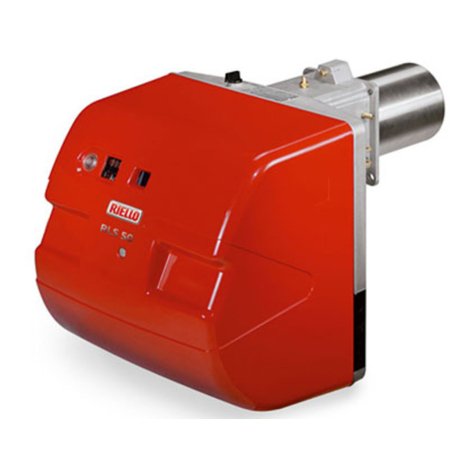
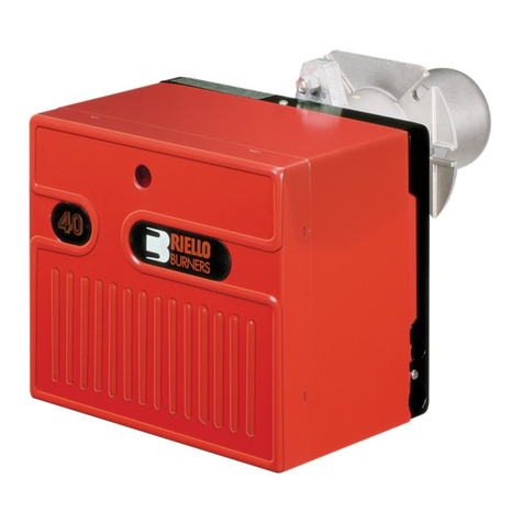
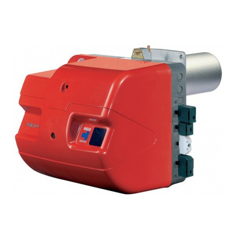
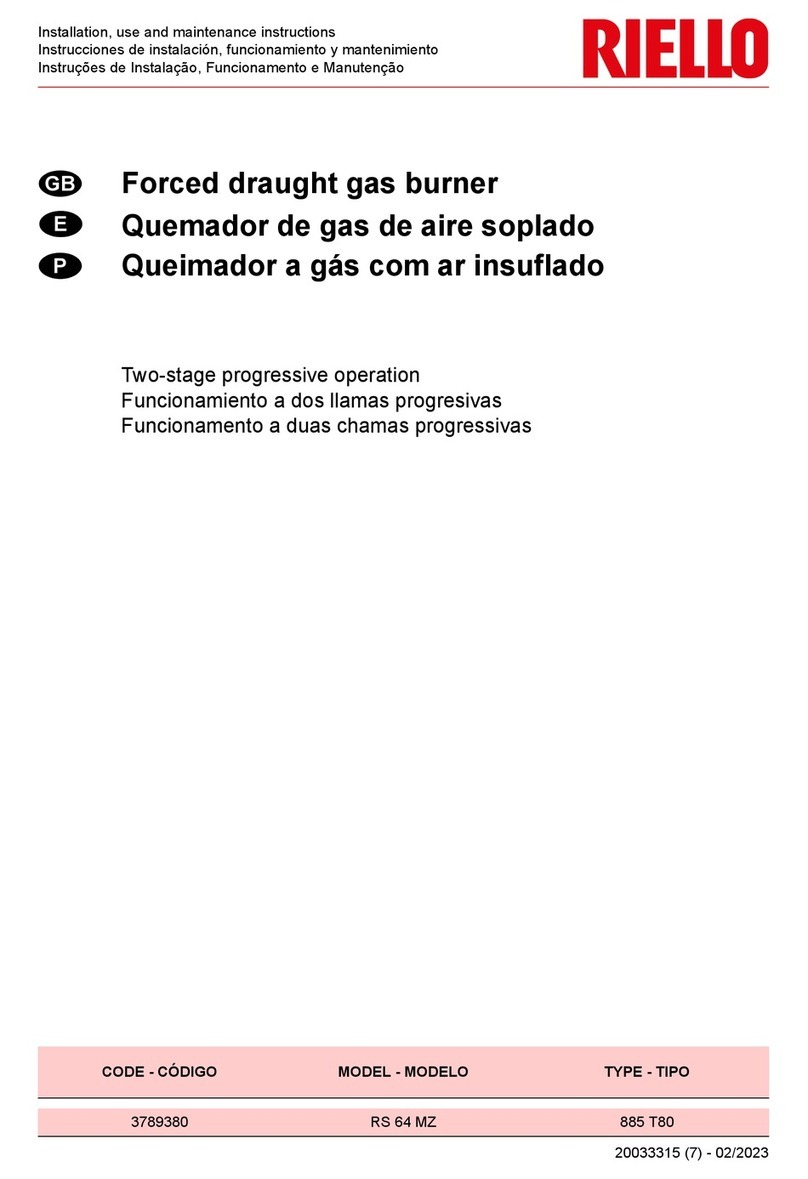
  9. Riello RLS Series Quick start guide

Riello RLS Series Quick start guide

20019832 (4) - 03/2014
Istruzioni per installazione, uso e manutenzione
Montage und Bedienungsanleitung
Installation, use and maintenance instructions
Instructions pour installation, utilisation et entretien
Bruciatori policombustibile gasolio/gas
Mehrstoffbrenner Heizöl/Gas
Dual fuel Gas-Oil/Gas burners
Brûleurs mixtes fioul/gaz
Funzionamento bistadio
Zweistufiger Betrieb
Two-stage operation
Fonctionnement à deux allures
CODICE - CODE MODELLO - MODELL
MODEL - MODELE TIPO - TYP
TYPE - TYPE
3091489 RLS 70 1489D
3091589 RLS 100 1589D
20019826 RLS 130 19826X
I
D
GB
F
3
INDICE
GASOLIO / GAS
Dati tecnici . . . . . . . . . . . . . . . . . . . . . . . . . . . . . . . . . . . . pagina 4
Accessori . . . . . . . . . . . . . . . . . . . . . . . . . . . . . . . . . . . . . . . . . . . 4
Descrizione bruciatore . . . . . . . . . . . . . . . . . . . . . . . . . . . . . . . . . 8
Imballo - Peso . . . . . . . . . . . . . . . . . . . . . . . . . . . . . . . . . . . . . . . 8
Ingombro . . . . . . . . . . . . . . . . . . . . . . . . . . . . . . . . . . . . . . . . . . . 8
Corredo . . . . . . . . . . . . . . . . . . . . . . . . . . . . . . . . . . . . . . . . . . . . 8
Campi di lavoro . . . . . . . . . . . . . . . . . . . . . . . . . . . . . . . . . . . . . 10
Caldaia di prova . . . . . . . . . . . . . . . . . . . . . . . . . . . . . . . . . . . . . 10
Caldaie commerciali. . . . . . . . . . . . . . . . . . . . . . . . . . . . . . . . . . 10
Installazione . . . . . . . . . . . . . . . . . . . . . . . . . . . . . . . . . . . . . . . . 12
Piastra caldaia . . . . . . . . . . . . . . . . . . . . . . . . . . . . . . . . . . . . . . 12
Lunghezza boccaglio . . . . . . . . . . . . . . . . . . . . . . . . . . . . . . . . . 12
Fissaggio del bruciatore alla caldaia . . . . . . . . . . . . . . . . . . . . . 12
GASOLIO
Scelta degli ugelli per 1° e 2° stadio. . . . . . . . . . . . . . . . . . . . . . 12
Montaggio degli ugelli. . . . . . . . . . . . . . . . . . . . . . . . . . . . . . . . . 12
Regolazioni prima dell’accensione. . . . . . . . . . . . . . . . . . . . . . . 14
GASOLIO / GAS
Impianto elettrico . . . . . . . . . . . . . . . . . . . . . . . . . . . . . . . . . . . . 16
Servomotore. . . . . . . . . . . . . . . . . . . . . . . . . . . . . . . . . . . . . . . . 20
GASOLIO
Pompa . . . . . . . . . . . . . . . . . . . . . . . . . . . . . . . . . . . . . . . . . . . . 20
Alimentazione combustibile . . . . . . . . . . . . . . . . . . . . . . . . . . . . 22
Collegamenti idraulici . . . . . . . . . . . . . . . . . . . . . . . . . . . . . . . . . 22
Innesco pompa. . . . . . . . . . . . . . . . . . . . . . . . . . . . . . . . . . . . . . 22
Regolazione bruciatore . . . . . . . . . . . . . . . . . . . . . . . . . . . . . . . 24
GAS
Pressione gas. . . . . . . . . . . . . . . . . . . . . . . . . . . . . . . . . . . . . . . 26
Linea alimentazione gas. . . . . . . . . . . . . . . . . . . . . . . . . . . . . . . 28
Regolazioni prima dell’accensione. . . . . . . . . . . . . . . . . . . . . . . 30
Avviamento bruciatore . . . . . . . . . . . . . . . . . . . . . . . . . . . . . . . . 30
Accensione bruciatore . . . . . . . . . . . . . . . . . . . . . . . . . . . . . . . . 30
Regolazione bruciatore . . . . . . . . . . . . . . . . . . . . . . . . . . . . . . . 30
Funzionamento a GPL-Propano-Butano . . . . . . . . . . . . . . . . . . 34
GASOLIO / GAS
Manutenzione. . . . . . . . . . . . . . . . . . . . . . . . . . . . . . . . . . . . . . . 36
Difficoltà di funzionamento e relative cause. . . . . . . . . . . . . . . . 38
Schema idraulico . . . . . . . . . . . . . . . . . . . . . . . . . . . . . . . . . . . . 38
Controllo della combustione (a gas). . . . . . . . . . . . . . . . . . . . . . 40
Corrente elettrica alla cellula UV . . . . . . . . . . . . . . . . . . . . . . . . 40
Funzionamento bruciatore . . . . . . . . . . . . . . . . . . . . . . . . . . . . . 40
I
INHALT
HEIZÖL / GAS
Technische Angaben. . . . . . . . . . . . . . . . . . . . . . . . . . . . . . Seite 5
Zubehör. . . . . . . . . . . . . . . . . . . . . . . . . . . . . . . . . . . . . . . . . . . . . 5
Brennerbeschreibung . . . . . . . . . . . . . . . . . . . . . . . . . . . . . . . . . . 9
Verpackung - Gewicht. . . . . . . . . . . . . . . . . . . . . . . . . . . . . . . . . . 9
Abmessungen . . . . . . . . . . . . . . . . . . . . . . . . . . . . . . . . . . . . . . . . 9
Ausstattung . . . . . . . . . . . . . . . . . . . . . . . . . . . . . . . . . . . . . . . . . . 9
Regelbereiche. . . . . . . . . . . . . . . . . . . . . . . . . . . . . . . . . . . . . . . 11
Prüfkessel . . . . . . . . . . . . . . . . . . . . . . . . . . . . . . . . . . . . . . . . . . 11
Handelsübliche Kessel . . . . . . . . . . . . . . . . . . . . . . . . . . . . . . . . 11
Installation. . . . . . . . . . . . . . . . . . . . . . . . . . . . . . . . . . . . . . . . . . 13
Kesselplatte. . . . . . . . . . . . . . . . . . . . . . . . . . . . . . . . . . . . . . . . . 13
Flammrohrlänge . . . . . . . . . . . . . . . . . . . . . . . . . . . . . . . . . . . . . 13
Befestigung des Brenners am Heizkessel . . . . . . . . . . . . . . . . . 13
HEIZÖL
Wahl der Düsen für 1. und 2. Stufe. . . . . . . . . . . . . . . . . . . . . . . 13
Düsenmontage . . . . . . . . . . . . . . . . . . . . . . . . . . . . . . . . . . . . . . 13
Einstellungen vor der Zündung . . . . . . . . . . . . . . . . . . . . . . . . . . 15
HEIZÖL / GAS
Elektroanlage . . . . . . . . . . . . . . . . . . . . . . . . . . . . . . . . . . . . . . . 17
Stellantrieb . . . . . . . . . . . . . . . . . . . . . . . . . . . . . . . . . . . . . . . . . 21
HEIZÖL
Pumpe. . . . . . . . . . . . . . . . . . . . . . . . . . . . . . . . . . . . . . . . . . . . . 21
Brennstoffzuführung . . . . . . . . . . . . . . . . . . . . . . . . . . . . . . . . . . 23
Hydraulikanschlüsse . . . . . . . . . . . . . . . . . . . . . . . . . . . . . . . . . . 23
Einschalten der Pumpe. . . . . . . . . . . . . . . . . . . . . . . . . . . . . . . . 23
Brennereinstellung . . . . . . . . . . . . . . . . . . . . . . . . . . . . . . . . . . . 25
GAS
Gasdruck. . . . . . . . . . . . . . . . . . . . . . . . . . . . . . . . . . . . . . . . . . . 27
Gaszuleitung . . . . . . . . . . . . . . . . . . . . . . . . . . . . . . . . . . . . . . . . 29
Einstellungen vor der Zündung . . . . . . . . . . . . . . . . . . . . . . . . . . 31
Anfahren des Brenners . . . . . . . . . . . . . . . . . . . . . . . . . . . . . . . . 31
Zündung des Brenners . . . . . . . . . . . . . . . . . . . . . . . . . . . . . . . . 31
Brennereinstellung . . . . . . . . . . . . . . . . . . . . . . . . . . . . . . . . . . . 31
Flüssigas-Propangas-Butangas-Betrieb . . . . . . . . . . . . . . . . . . . 35
HEIZÖL / GAS
Wartung. . . . . . . . . . . . . . . . . . . . . . . . . . . . . . . . . . . . . . . . . . . . 37
Schwierigkeiten beim Anfahren und Ursachen . . . . . . . . . . . . . . 39
Hydraulikschaltplan. . . . . . . . . . . . . . . . . . . . . . . . . . . . . . . . . . . 39
Überprüffung der Verbrennung bei Gasbetrieb. . . . . . . . . . . . . . 41
Strom an der UV Zelle. . . . . . . . . . . . . . . . . . . . . . . . . . . . . . . . . 41
Brennerbetrieb . . . . . . . . . . . . . . . . . . . . . . . . . . . . . . . . . . . . . . 41
D
CONTENTS
LIGHT OIL / GAS
Technical data . . . . . . . . . . . . . . . . . . . . . . . . . . . . . . . . . . .page 6
Accessories . . . . . . . . . . . . . . . . . . . . . . . . . . . . . . . . . . . . . . . . . 6
Burner description . . . . . . . . . . . . . . . . . . . . . . . . . . . . . . . . . . . . 9
Packaging - Weight . . . . . . . . . . . . . . . . . . . . . . . . . . . . . . . . . . . 9
Max. dimensions . . . . . . . . . . . . . . . . . . . . . . . . . . . . . . . . . . . . . 9
Standard equipment . . . . . . . . . . . . . . . . . . . . . . . . . . . . . . . . . . . 9
Firing rates . . . . . . . . . . . . . . . . . . . . . . . . . . . . . . . . . . . . . . . . . .11
Test boiler. . . . . . . . . . . . . . . . . . . . . . . . . . . . . . . . . . . . . . . . . . .11
Commercial boilers. . . . . . . . . . . . . . . . . . . . . . . . . . . . . . . . . . . .11
Installation . . . . . . . . . . . . . . . . . . . . . . . . . . . . . . . . . . . . . . . . . 13
Boiler plate . . . . . . . . . . . . . . . . . . . . . . . . . . . . . . . . . . . . . . . . . 13
Blast tube length . . . . . . . . . . . . . . . . . . . . . . . . . . . . . . . . . . . . 13
Securing the burner to the boiler . . . . . . . . . . . . . . . . . . . . . . . . 13
LIGHT OIL
Choice of nozzles for the 1st and 2nd stage . . . . . . . . . . . . . . . 13
Nozzle assembly . . . . . . . . . . . . . . . . . . . . . . . . . . . . . . . . . . . . 13
Calibrations before firing . . . . . . . . . . . . . . . . . . . . . . . . . . . . . . 15
LIGHT OIL / GAS
Electrical system . . . . . . . . . . . . . . . . . . . . . . . . . . . . . . . . . . . . 17
Servomotor. . . . . . . . . . . . . . . . . . . . . . . . . . . . . . . . . . . . . . . . . 21
LIGHT OIL
Pump . . . . . . . . . . . . . . . . . . . . . . . . . . . . . . . . . . . . . . . . . . . . . 21
Fuel supply. . . . . . . . . . . . . . . . . . . . . . . . . . . . . . . . . . . . . . . . . 23
Hydraulic connections . . . . . . . . . . . . . . . . . . . . . . . . . . . . . . . . 23
Pump priming . . . . . . . . . . . . . . . . . . . . . . . . . . . . . . . . . . . . . . . 23
Burner calibration. . . . . . . . . . . . . . . . . . . . . . . . . . . . . . . . . . . . 25
GAS
Gas pressure . . . . . . . . . . . . . . . . . . . . . . . . . . . . . . . . . . . . . . . 27
Gas line . . . . . . . . . . . . . . . . . . . . . . . . . . . . . . . . . . . . . . . . . . . 29
Adjustment before firing . . . . . . . . . . . . . . . . . . . . . . . . . . . . . . . 31
Burner starting . . . . . . . . . . . . . . . . . . . . . . . . . . . . . . . . . . . . . . 31
Burner firing . . . . . . . . . . . . . . . . . . . . . . . . . . . . . . . . . . . . . . . . 31
Burner calibration. . . . . . . . . . . . . . . . . . . . . . . . . . . . . . . . . . . . 31
LPG-Propane-Butane operation. . . . . . . . . . . . . . . . . . . . . . . . . 35
LIGHT OIL / GAS
Maintenance. . . . . . . . . . . . . . . . . . . . . . . . . . . . . . . . . . . . . . . . 37
Burner starting difficulties and their causes . . . . . . . . . . . . . . . . 39
Hydraulic system layout . . . . . . . . . . . . . . . . . . . . . . . . . . . . . . . 39
Gas combustion checks . . . . . . . . . . . . . . . . . . . . . . . . . . . . . . . 41
Current to the UV photocell . . . . . . . . . . . . . . . . . . . . . . . . . . . . 41
Burner operation. . . . . . . . . . . . . . . . . . . . . . . . . . . . . . . . . . . . . 41
GB
INDEX
FIOUL / GAZ
Données techniques . . . . . . . . . . . . . . . . . . . . . . . . . . . . . . page 7
Accessoires. . . . . . . . . . . . . . . . . . . . . . . . . . . . . . . . . . . . . . . . . . 7
Description brûleur . . . . . . . . . . . . . . . . . . . . . . . . . . . . . . . . . . . . 9
Emballage - Poids. . . . . . . . . . . . . . . . . . . . . . . . . . . . . . . . . . . . . 9
Encombrement . . . . . . . . . . . . . . . . . . . . . . . . . . . . . . . . . . . . . . . 9
Equipement standard . . . . . . . . . . . . . . . . . . . . . . . . . . . . . . . . . . 9
Plages de puissance. . . . . . . . . . . . . . . . . . . . . . . . . . . . . . . . . . 11
Chaudière d’essai . . . . . . . . . . . . . . . . . . . . . . . . . . . . . . . . . . . . 11
Chaudières commerciales. . . . . . . . . . . . . . . . . . . . . . . . . . . . . . 11
Installation. . . . . . . . . . . . . . . . . . . . . . . . . . . . . . . . . . . . . . . . . . 13
Plaque chaudière . . . . . . . . . . . . . . . . . . . . . . . . . . . . . . . . . . . . 13
Longueur buse . . . . . . . . . . . . . . . . . . . . . . . . . . . . . . . . . . . . . . 13
Fixation du brûleur à la chaudière. . . . . . . . . . . . . . . . . . . . . . . . 13
FIOUL
Choix des gicleurs pour 1ère et 2ème allure. . . . . . . . . . . . . . . . 13
Montage des gicleurs . . . . . . . . . . . . . . . . . . . . . . . . . . . . . . . . . 13
Réglages avant l’allumage . . . . . . . . . . . . . . . . . . . . . . . . . . . . . 15
FIOUL / GAZ
Installation électrique . . . . . . . . . . . . . . . . . . . . . . . . . . . . . . . . . 17
Servomoteur . . . . . . . . . . . . . . . . . . . . . . . . . . . . . . . . . . . . . . . . 21
FIOUL
Pompe. . . . . . . . . . . . . . . . . . . . . . . . . . . . . . . . . . . . . . . . . . . . . 21
Alimentation combustible . . . . . . . . . . . . . . . . . . . . . . . . . . . . . . 23
Raccordements hydrauliques . . . . . . . . . . . . . . . . . . . . . . . . . . . 23
Amorçage pompe . . . . . . . . . . . . . . . . . . . . . . . . . . . . . . . . . . . . 23
Réglage brûleur. . . . . . . . . . . . . . . . . . . . . . . . . . . . . . . . . . . . . . 25
GAZ
Pression du gaz . . . . . . . . . . . . . . . . . . . . . . . . . . . . . . . . . . . . . 27
Ligne alimentation gaz . . . . . . . . . . . . . . . . . . . . . . . . . . . . . . . . 29
Réglages avant l’allumage . . . . . . . . . . . . . . . . . . . . . . . . . . . . . 31
Démarrage brûleur . . . . . . . . . . . . . . . . . . . . . . . . . . . . . . . . . . . 31
Allumage brûleur. . . . . . . . . . . . . . . . . . . . . . . . . . . . . . . . . . . . . 31
Réglage brûleur. . . . . . . . . . . . . . . . . . . . . . . . . . . . . . . . . . . . . . 31
Fonctionnement au GPL-Propane-Butane . . . . . . . . . . . . . . . . . 35
FIOUL / GAZ
Entretien . . . . . . . . . . . . . . . . . . . . . . . . . . . . . . . . . . . . . . . . . . . 37
Difficultés de fonctionnement et causes possibles . . . . . . . . . . . 39
Schéma hydraulique . . . . . . . . . . . . . . . . . . . . . . . . . . . . . . . . . . 39
Contrôle de la combustion (pour gaz). . . . . . . . . . . . . . . . . . . . . 41
Courant à la cellule UV . . . . . . . . . . . . . . . . . . . . . . . . . . . . . . . . 41
Fonctionnement brûleur . . . . . . . . . . . . . . . . . . . . . . . . . . . . . . . 41
F
4
DATI TECNICI
(1)
Condizioni di riferimento: Temperatura ambiente 20°C - Pressione barometrica 1000 mbar - Altitudine 100 m s.l.m.
(2)
Pressione alla presa 18)(A)p.8 con pressione zero in camera di combustione ed alla potenza massima del bruciatore.
(3)
Pressione sonora misurata nel laboratorio combustione del costruttore, con bruciatore funzionante su caldaia di prova, alla potenza massima.
ACCESSORI
(su richiesta):
• KIT PER ALLUNGARE LA TESTA DI COMBUSTIONE
L =testa standard
L1 =testa lunga ottenibile con il kit
COD. 3010345 L = 250 mm L1 = 385 mm • RLS 70
COD. 3010346 L = 250 mm L1 = 385 mm • RLS 100
COD. 3010347 L = 250 mm L1 = 385 mm • RLS 130
•RAMPE GAS SECONDO NORMA EN 676 (complete di valvole, regolatore di pressione e filtro): vedere a pagina 28.
Tutte le operazioni di installazione, manutenzione e smontaggio devono assolutamente essere eseguite con rete elettrica staccata.
l bruciatore richiede una manutenzione periodica, che deve essere eseguita da personale abilitato e in conformità alle leggi e norma-
tive locali.
MODELLO RLS 70 RLS 100 RLS 130
POTENZA
(1)
PORTATA
(1)
2° stadio kW 465 - 814
39 - 69 698 - 1163
59 - 98 930 - 1395
78 - 118
kg/h
min. 1° stadio kW 232
19 349
29,5 465
39
kg/h
COMBUSTIBILI GASOLIO, viscosità max. a 20 °C: 6 mm
2
/s (1,5 °E - 6 cSt)
GAS NATURALE: G20 (metano) - G21 - G22 - G23 - G25
GPL - G30 (propano) - G31 (butano)
Pressione gas alla potenza max.
(2)
Gas: G20/G25/G31 mbar 6,2/7,5/7,8 10/13/12 11,5/14,4/15
FUNZIONAMENTO - Intermittente (min. 1 arresto in 24 ore)
- Bistadio (alta e bassa fiamma) e monostadio (tutto - niente)
UGELLI numero 2
IMPIEGO STANDARD Caldaie: ad acqua, a vapore, ad olio diatermico
TEMPERATURA AMBIENTE °C 0 - 40
TEMPERATURA ARIA COMBURENTE °C max 60
ALIMENTAZIONE ELETTRICA PRINCIPALE Ph/V/Hz 3/220-380/60
ALIMENTAZIONE ELETTRICA CIRCUITO AUSILIARIO Ph/V/Hz 1N/220/60
MOTORE VENTILATORE rpm
V
Hz
W
A
3475
220/380
60
1100
4,2/2,4
3500
220/380
60
2200
8,1/4,7
3500
220/380
60
2200
8,1/4,7
MOTORE POMPA
Condensatore
rpm
V
Hz
W
A
µF
3300
220
60
550
4,6
16
TRASFORMATORE D’ACCENSIONE V1 - V2
I1 - I2 230 V - 2 x 5 kV
1,9 A - 30 mA
POMPA portata (a 12 bar)
campo di pressione
temperatura combustibile
kg/h
bar
° C max
220
10 - 20
60
POTENZA ELETTRICA ASSORBITA W max 2000 2700 3200
GRADO DI PROTEZIONE IP 44
CONFORMITÀ DIRETTIVE CE 2006/42 - 2004/108 - 2006/95
RUMOROSITÀ
(3)
dBA 74 77,5 80
NOTA.
L’installatore è responsabile per l’eventuale aggiunta di organi di sicurezza non previsti in questo manuale.
5
TECHNISCHE ANGABEN
(1)
Bezugsbedingungen: Raumtemperatur 20°C - Barometrischer Druck 1000 mbar - Höhe 100 m ü.d.M.
(2)
Druck am Anschluß 18)(A)S.8 bei druckloser Brennkammer und bei Höchstleistung des Brenners.
(3)
Schalldruck, im Brennprüflabor des Herstellers mit Brenner auf Prüfkessel bei Höchstleistung.
ZUBEHÖR
(auf Wunsch):
• KIT ZUR VERLÄNGERUNG DES FLAMMKOPFES
L =Standardlänge
L1 =Mit Kit erreichbare Länge
COD. 3010345 L = 250 mm L1 = 385 mm • RLS 70
COD. 3010346 L = 250 mm L1 = 385 mm • RLS 100
COD. 3010347 L = 250 mm L1 = 385 mm • RLS 130
•GASARMATUREN GEMÄß NORM EN 676 (mit Ventilen, Druckregler und Filter): siehe Seite 28.
Alle Arbeiten zur Installation, Wartung und Demontage müssen unbedingt bei abgeschaltetem Stromnetz ausgeführt werden.
Der Brenner erfordert eine periodische Wartung, die durch befähigtes Personal und in Übereinstimmung mit den örtlichen Gesetzen
und Vorschriften auszuführen ist.
MODELL RLS 70 RLS 100 RLS 130
LEISTUNG
(1)
DURCHSATZ
(1)
2. Stufe kW 465 - 814
39 - 69 698 - 1163
59 - 98 930 - 1395
78 - 118
kg/h
min. 1. Stufe kW 232
19 349
29,5 465
39
kg/h
BRENNSTOFF HEIZÖL EL, Viskosität b. 20 °C: 6 mm
2
/s max (1,5 °E - 6 cSt)
ERDGAS: G20 (Methangas) - G21 - G22 - G23 - G25
FLÜSSIGAS - G30 (Propangas) - G31 (Butangas)
Gasdruck bei Höchstleistung.
(2)
Gas: G20/G25/G31 mbar 6,2/7,5/7,8 10/13/12 11,5/14,4/15
BETRIEB - Aussetzend (min. 1 Halt in 24 Std)
- Zweistufig (hohe und niedrige Flamme) - einstufig (alles - nichts)
DÜSEN Stück 2
STANDARDEINSATZ Heizkessel: mit Wasser, Dampf, diathermischem Öl
RAUMTEMPERATUR °C 0 - 40
TEMPERATUR VERBRENNUNGSLUFT °C max 60
HAUPTSTROMVERSORGUNG Ph/V/Hz 3/220-380/60
STROMVERSORGUNG FÜR HILFSSCHALTUNG Ph/V/Hz 1N/220/60
GEBLÄSEMOTOR rpm
V
Hz
W
A
3475
220/380
60
1100
4,2/2,4
3500
220/380
60
2200
8,1/4,7
3500
220/380
60
2200
8,1/4,7
PUMPENMOTOR
Kondensator
rpm
V
Hz
W
A
µF
3300
220
60
550
4,6
16
ZÜNDTRANSFORMATOR V1 - V2
I1 - I2 230 V - 2 x 5 kV
1,9 A - 30 mA
PUMPE Fördermenge (bei 12 bar)
Druckbereich
Brennstofftemperatur
kg/h
bar
° C max
220
10 - 20
60
ELEKTRISCHE LEISTUNGSAUFNAHME W max 2000 2700 3200
SCHUTZART IP 44
CE-NORMGERECHT 2006/42 - 2004/108 - 2006/95
SCHALLDRUCKPEGEL
(3)
dBA 74 77,5 80
Wichtiger Hinweis:
Der Installateur haftet für den eventuellen Zusats von sicherheitsteilen, die nicht in dieser Betriebsanleitung vorgesehen sind.
6
TECHNICAL DATA
(1)
Reference conditions: Ambient temperature 20°C - Barometric pressure 1000 mbar - Altitude 100 m s.l.m.
(2)
Pressure at test point 18)(A)p.8 with zero pressure in the combustion chamber and maximum burner output.
(3)
Sound pressure measured in manufacturer’s combustion laboratory, with burner operating on test boiler and at maximum rated output.
ACCESSORIES
(optional):
• KIT FOR LENGTHNING THE COMBUSTION HEAD
L =Standard length
L1 =Lenght obtainable with the kit
COD. 3010345 L = 250 mm L1 = 385 mm • RLS 70
COD. 3010346 L = 250 mm L1 = 385 mm • RLS 100
COD. 3010347 L = 250 mm L1 = 385 mm • RLS 130
•GAS TRAIN ACCORDING TO REGULATION EN 676 (with valves, pressure governor and filter): see page 28.
All the installation, maintenance and disassembly operations must be carried out with the electricity supply disconnected.
The burner requires periodic maintenance carried out by a qualified and authorised technician in conformity with legislation and local
standards.
MODEL RLS 70 RLS 100 RLS 130
OUTPUT
(1)
DELIVERY
(1)
2nd stage kW 465 - 814
39 - 69 698 - 1163
59 - 98 930 - 1395
78 - 118
kg/h
min. 1st stage kW 232
19 349
29.5 465
39
kg/h
FUEL LIGHT OIL. viscosity at 20 °C: 6 mm
2
/s max (1.5 °E - 6 cSt)
NATURAL GAS: G20 (methane) - G21 - G22 - G23 - G25
GPL - G30 (propane) - G31 (butane)
Gas pressure at maximum delivery
(2)
Gas: G20/G25/G31 mbar 6.2/7.5/7.8 10/13/12 11.5/14.4/15
OPERATION - Intermittent (min. 1 stop in 24 hours)
- Two-stage (high and low flame) and single-stage (all - nothing)
NOZZLES number 2
STANDARD APPLICATIONS Boilers: water. steam. diathermic oil
AMBIENT TEMPERATUR °C 0 - 40
COMBUSTION AIR TEMPERATURE °C max 60
MAIN ELECTRICAL SUPPLY Ph/V/Hz 3/220-380/60
CONTROL CIRCUIT POWER SUPPLY Ph/V/Hz 1N/220/60
FAN MOTOR rpm
V
Hz
W
A
3475
220/380
60
1100
4,2/2,4
3500
220/380
60
2200
8,1/4,7
3500
220/380
60
2200
8,1/4,7
PUMP MOTOR
Capacitor
rpm
V
Hz
W
A
µF
3300
220
60
550
4,6
16
IGNITION TRANSFORMER V1 - V2
I1 - I2 230 V - 2 x 5 kV
1,9 A - 30 mA
PUMP delivery (at 12 bar)
pressure range
fuel temperatur
kg/h
bar
° C max
220
10 - 20
60
ELECTRICAL POWER CONSUMPTION W max 2000 2700 3200
ELECTRICAL PROTECTION IP 44
CONFORMITY TO EEC DIRECTIVES 2006/42 - 2004/108 - 2006/95
NOISE LEVELS
(3)
dBA 74 77,5 80
Important:
The installer is responsible for the addition of any safety device not forseen in the present manual.
7
DONNÉES TECHNIQUES
(1)
Conditions deréférence:Température ambiante 20°C -Pression barométrique1000 mbar- Altitude 100 m au-dessus duniveaude lamer.
(2)
Pression à la prise18)(A)p.8, avecune pression nulle dans lachambrede combustionet àla puissance maximum du brûleur.
(3)
Pression acoustique mesuréedans le laboratoire combustion du constructeur, lebrûleur fonctionnantsur une chaudière d’essaià la puissancemaximum.
ACCESSOIRES
(sur demande):
• KIT POUR ALLONGER LA TETE DE COMBUSTION
L =longueur standard
L1 =longueur pouvant être obtenue avec le kit
COD. 3010345 L = 250 mm L1 = 385 mm • RLS 70
COD. 3010346 L = 250 mm L1 = 385 mm • RLS 100
COD. 3010347 L = 250 mm L1 = 385 mm • RLS 130
•RAMPES GAZ SELON LA NORME EN 676 (avec vannes, régulateur de pression et filtre): voir p. 28.
Toutes les opérations d’installation, entretien et démontage doivent être effectuées avec le réseau électrique débranché.
Le brûleur nécessite d’un entretien périodique, qui doit être effectué par du personnel expérimenté et conformément aux lois et aux
réglementations locales.
MODELE RLS 70 RLS 100 RLS 130
PUISSANCE
(1)
DEBIT
(1)
2ème allure kW 465 - 814
39 - 69 698 - 1163
59 - 98 930 - 1395
78 - 118
kg/h
min. 1ère
allure kW 232
19 349
29,5 465
39
kg/h
COMBUSTIBLES FIOUL DOMESTIQUE, viscosité à 20 °C: 6 mm
2
/s max. (1,5 °E - 6 cSt)
GAZ NATUREL: G20 (méthano) - G21 - G22 - G23 - G25
GPL - G30 (propane) - G31 (butane)
Pression du gaz à la puissance max.
(2)
Gaz: G20/G25/G31 mbar 6,2/7,5/7,8 10/13/12 11,5/14,4/15
FONCTIONNEMENT - Intermittent (1 arrêt min en 24 heures)
- 2 allures (flamme haute et basse) et une allure (tout - rien)
GICLEURS numero 2
EMPLOI STANDARD Chaudières à eau, à vapeur, à huile diathermique
TEMPERATURE AMBIANTE °C 0 - 40
TEMPERATURE AIR COMBURANT °C max 60
ALIMENTATION ÉLECTRIQUE GÉNÉRALE Ph/V/Hz 3/220-380/60
ALIMENTATION ÉLECTRIQUE DU CIRCUIT AUXILIA-
IRE Ph/V/Hz 1N/220/60
MOTEUR VENTILATEUR rpm
V
Hz
W
A
3475
220/380
60
1100
4,2/2,4
3500
220/380
60
2200
8,1/4,7
3500
220/380
60
2200
8,1/4,7
MOTEUR POMPE
Condensateur
rpm
V
Hz
W
A
µF
3300
220
60
550
4,6
16
TRANSFORMATEUR D’ALLUMAGE V1 - V2
I1 - I2 230 V - 2 x 5 kV
1,9 A - 30 mA
POMPE débit (à 12 bar)
plage de pression
température combustible
kg/h
bar
° C max
220
10 - 20
60
PUISSANCE ELECTRIQUE ABSORBEE W max 2000 2700 3200
DEGRE DE PROTECTION IP 44
CONFORMÉMENT AUX DIRECTIVES CE 2006/42 - 2004/108 - 2006/95
NIVEAU DE BRUIT
(3)
dBA 74 77,5 80
Attention:
Si l’installateur ajoute des organes de sécurité non prévus dans ce manuel, il en assume la responsabilité.
8
DESCRIZIONE BRUCIATORE
1 Testa di combustione
2 Elettrodi di accensione
3 Vite per regolazione testa di combustione
4 Manicotto
5 Relè
6 Motore ventilatore
7 Contattore motore e relè termico con pul-
sante di sblocco
8 LED PANEL
9 Morsettiera
10 Passacavi per collegamenti elettrici a cura
dell’installatore
11 Due interruttori elettrici:
- uno per “acceso - spento bruciatore”
- uno per “1° - 2° stadio”
12 Apparecchiatura elettrica con avvisatore
luminoso di blocco e pulsante di sblocco
13 Visore fiamma
14 Pressostato aria di minima
(tipo differenziale)
15 Guide per apertura bruciatore ed ispezione
alla testa di combustione
16 Valvola di sicurezza
17 Valvole di 1° e 2° stadio
18 Presa di pressione gas e vite fissa testa
19 Presa di pressione aria
20 Servomotore.
Durante la sosta del bruciatore la serranda
dell’aria è completamente chiusa per ridurre
al minimo le dispersioni termiche della cal-
daia dovute al tiraggio del camino che richi-
ama l’aria dalla bocca di aspirazione del
ventilatore.
21 Motore pompa
22 Serranda aria
23 Ingresso aria nel ventilatore
24 Pompa
25 Condotto arrivo gas
26 Flangia per il fissaggio alla caldaia
27 Disco di stabilità fiamma
28 Viti per il fissaggio ventilatore al manicotto
29 Cellula UV
30 Commutatore olio - gas
Vi sono due possibilità di blocco del bruciatore:
Blocco apparecchiatura: l’accensione del pul-
sante dell’apparecchiatura 12)(A) avverte che il
bruciatore è in blocco.
Per sbloccare premere il pulsante.
Blocco motore: per sbloccare premere il pul-
sante del relè termico 7)(A).
IMBALLO - PESO (B) - misure indicative
• L’ imballo del bruciatore appoggia su una
pedana in legno particolarmente adatta ai car-
relli elevatori. Le dimensioni di ingombro
dell'imballo sono riportate nella tabella (B).
• Il peso del bruciatore completo di imballo è
indicato nella tabella (B).
INGOMBRO (C) - misure indicative
L'ingombro del bruciatore è riportato in fig. (C).
Tener presente che per ispezionare la testa di
combustione il bruciatore deve essere aperto
arretrandone la parte posteriore sulle guide.
L'ingombro del bruciatore aperto è indicato dalla
quota I.
CORREDO
1 - Flangia per rampa gas
1 - Guarnizione per flangia
4 - Viti per fissare la flangia M 10 x 35
1 - Schermo termico
4 - Viti per fissare la flangia del bruciatore alla
caldaia: M 12 x 35
2 - Tubi flessibili
2 - Nipples per tubi flessibili con guarnizioni
1 - KIT per funzionamento a GPL
1 - Etichetta per funzionamento GPL.
1 - Istruzione
1 - Catalogo ricambi
(A)
mm A B C kg
RLS 70 1190 740 692 70
RLS 100 1190 740 692 73
RLS 130 1190 740 692 76
(B)
mm A B C D E F G H I L M N O
RLS 70 691 296 395 555 840 250 179 430 1161 214 134 221 2”
RLS 100 707 312 395 555 840 250 189 430 1161 214 134 221 2”
RLS 130 733 338 395 555 840 250 189 430 1161 214 134 221 2”
(C)
D1175
D36
D1176
9
BRENNERBESCHREIBUNG (A)
1 Flammkopf
2 Zündelektroden
3 Einstellschraube Flammkopf
4 Gasanschluß-Muffe
5 Relais
6 Gebläsemotor
7 Motorschaltglied und Wärmerelais mit
Entriegelungsschalter
8 LED PANEL
9 Klemmenbrett
10 Kabeldurchgänge für die Elektroanschlüsse
vom Installateur auszuführen
11 Zwei Schalter:
- einerfür“Brennereingeschaltet-ausgeschaltet”
- einer für “1. - 2. Stufe”
12 Steuergerät mit Kontrollampe für Störab-
schaltung und Entriegelungsschalter
13 Sichtfenster
14 Mindestluftdruckwächter
(Differentialtyp)
15 Gleitschienen zum Ausschwenken des Bren-
ners und für die Kontrolle des Flammkopfs
16 Sicherheitsventil
17 Ventile 1. und 2. Stufe
18 Luftdruckentnahmestelle und Befestigungss-
chraube des Flammkopfes
19 Luftdruckentnahmestelle
20 Stellantrieb.
Bei Brennerstillstand ist die Luftklappe
geschlossen, um die Wärmeverluste des
Kessels durch den Kaminzug mit Luftnach-
führung von der Saugöffnung des Gebläses
zu vermeiden.
21 Pumpenmotor
22 Luftklappe
23 Lufteinlaß zum Gebläse
24 Pumpe
25 Gaszuleitung
26 Befestigungsflansch am Kessel
27 Scheibe für Flammenstabilität
28 Befestigungsschraube des Gebläse an der
Gasanschluß-Muffe
29 UV Zelle
30 ÖL/GAS Umschalter
Die Störabschaltungen des Brenners können
zweierlei Art sein:
Störabschaltung des Gerätes: Das Aufleuchten
des Druckknopfes des Gerätes 12)(A) weist auf
eine Störabschaltung des Brenners hin.
Zur Entriegelung den Druckknopf drücken.
Störabschaltung des Motors: Entriegelung durch
Drükken auf den Druckknopf des Überstro-
mauslösers 7)(A).
VERPACKUNG - GEWICHT (B) - Richtwerte
• Der Brenner steht auf einem besonders
fürdie Handhabung mit Hubwagen geeignetem
Holzrahmen. Die Außenabmessungen der Ver-
packung sind in Tabelle (B) aufgeführt.
• Das Gesamtgewicht des Brenners ein-
schließlich Verpackung wird aus Tabelle (B)
ersichtlich (B).
ABMESSUNGEN (C) - Richtwerte
Die Brennerabmessungen sind in der Abb. (C)
angeführt.
Zur Inspektion des Flammkopfes muß der Bren-
ner geöffnet und der hintere Teil auf den
Gleitschienen zurückgeschoben werden.
Die Abmessungen des offenen Brenners sind
unter I aufgeführt.
AUSSTATUNG
1 - Flansch für Gasarmaturen
1 - Dichtung für Flansch
4 - Schrauben für die Befestigung des M 10 x
35 Flansches
1 - Wärmeschild
4 - Schrauben für die Befestigung des Bren-
nerflanschs am Kessel: M 12 x 35
2 - Schläuche
2 - Schlauchnippel mit Dichtungen
1 - KIT für Flussigas-Betrieb
1 - Selbstkleberschild für Flüssigasbetrieb
1 - Anleitung
1 - Ersatzteile Katalog
BURNER DESCRIPTION (A)
1 Combustion head
2 Ignition electrodes
3 Screw for combustion head adjustment
4 Sleeve
5 Relay
6 Fan motor
7 Motor contactor and thermal cut-out with
reset button
8 LED PANEL
9 Terminal strip
10 Fairleads for electrical connections by
installer
11 Two switches:
- one “burner off - on”
- one for “1st - 2nd stage”
12 Control box with lock-out pilot light and lock-
out reset button
13 Flame inspection window
14 Minimum air pressure switch
(differential operating type)
15 Slide bars for opening the burner and
inspecting the combustion head
16 Safety solenoid valve
17 1st and 2nd stage valves
18 Gas pressure test point and head fixing
screw
19 Air pressure test point
20 Servomotor.
When the burner is not operating the air gate
valve is fully closed in order to reduce to a
minimum heat dispersion from the boiler due
to the flue draught which draws air from the
fan suction inlet.
21 Pump motor
22 Air gate valve
23 Air inlet to fan
24 Pump
25 Gas input pipework
26 Boiler mounting flange
27 Flame stability disk
28 Screw securing fan to sleeve
29 Cell UV
30 OIL/GAS selector
Two types of burner failure may occur:
Control Box Lock-out: if the control box 12)(A)
pushbutton lights up, it indicates that the burner
is in lock-out.
To reset, press the pushbutton.
Motor trip: release by pressing the pushbutton
on thermal relay 7)(A).
PACKAGING - WEIGHT (B) - Approximate
measurements
• The burners stands on a wooden base which
can be lifted by fork-lifts. Outer dimensions of
packaging are indicated in (B).
• The weight of the burner complete with pack-
aging is indicated in Table (B).
MAX. DIMENSIONS (C) -Approximate mea-
surements
The maximum dimensions of the burner are
given in (C).
Bear in mind that inspection of the combustion
head requires the burner to be opened and the
rear part withdrawn on the slide bars.
The maximum dimension of the burnerwhen
open, without casing, is give in measurement I.
STANDARD EQUIPMENT
1 - Gas train flange
1 - Flange gasket
4 - Flange fixing screws M 10 x 35
1 - Thermal insulation screen
4 - Screws to secure the burner flange to the
boiler: M 12 x 35
2 - Flexible hoses
2 - Nipples for flexible hoses with gasket
1 - KIT for LPG operation
1 - Label for LPG operation
1 - Instruction booklet
1 - Spare parts list
DESCRIPTION BRULEUR (A)
1 Tête de combustion
2 Electrodes d'allumage
3 Vis pour réglage tête de combustion
4 Manchon
5 Relais
6 Moteur ventilateur
7 Contacteur moteur et relais thermique avec
bouton de déblocage
8 LED PANEL
9 Bornier
10 Passe-câbles pour les connexions électri-
ques à la charge de l’installateur
11 Deux interrupteurs électriques:
- un pour brûleur “allumé - éteint”
- un pour “1ère - 2ème allure”
12 Coffret de sécurité avec signal lumineux de
blocage et bouton de déblocage
13 Viseur flamme
14 Pressostat air seuil minimum
(type différentiel)
15 Guides pour ouverture brûleur et inspection
de la tête de combustion
16 Electrovanne de sécurité
17 Electrovannes de 1ère er 2ème allure
18 Prise de pression gaz et vis de fixation tête
19 Prise de pression air
20 Servomoteur.
Lors de l'arrêt du brûleur ce volet d'air est
complètement fermé afin de réduire le plus
possible les dispersions thermiques de la
chaudière causées par le tirage du conduit
de rappel d'air sur la bouche d'aspiration du
ventilateur.
21 Moteur pompe
22 Volet d'air
23 Prise de pression ventilateur
24 Pompe
25 Canalisation d’arrivée du gaz
26 Bride de fixation à la chaudière
27 Disque de stabilité de flamme
28 Vis de fixation ventilateur au manchon
29 Détecteur UV
30 Sélecteur FIOUL/GAZ
Il existe deux types de blocage du brûleur:
Blocage coffret: l'allumage du bouton du coffret
de sécurité 12)(A) avertit que le brûleur s'est
bloqué.
Pour le débloquer appuyer sur le bouton.
Blocage moteur: pour le débloquer appuyer sur
le bouton-poussoir du relais thermique 7)(A).
EMBALLAGE - POIDS (B) - Mesures indica-
tives
• Le brûleur est placé sur une palette qui peut
être soulevée par des chariots transpalettes.
Les dimensions d’encombrement de l’embal-
lage sont reportées dans le tableau (B).
• Le poids du brûleur avec son emballage est
indiqué dans le tab. (B).
ENCOMBREMENT (C) - Mesures indicatives
L'encombrement du brûleur est indiqué dans le
tab. (C).
Il faut tenir compte du fait que pour inspecter la
tête de combustion, le brûleur doit être ouvert, la
partie arrière reculée sur les guides.
L'encombrement du brûleur ouvert, sans carter,
est indiqué par la cote I.
EQUIPEMENT STANDARD
1 - Bride pour rampe gaz
1 - Joint pour bride
4 - Vis de fixation bride M 10 x 35
1 - Ecran thermique
4 - Vis pour fixer la bride du brûleur à la
chaudière: M 12 x 35
2 - Tuyaux flexibles
2 - Raccords pour tuyaux flexibles avec joints
1 - KIT pour fonctionnement au GPL
1 - Étiquette pour le fonctionnement au GPL
1 - Instructions
1 - Catalogue pièces détachées
10
CAMPI DI LAVORO (A)
I bruciatori RLS 70-100-130 possono funzionare
in due modi: monostadio o bistadio.
La POTENZA MASSIMA va scelta entro l'area
A.
Per utilizzare anche l’area B (RLS 130) occorre
la pretaratura della testa di combustione spie-
gata a pag. 12.
La POTENZA MINIMA non deve essere inferi-
ore al limite minimo del diagramma:
RLS 70 = 232 kW = 19,0 kg/h
RLS 100 = 349 kW = 29,5 kg/h
RLS 130 = 465 kW = 39,0 kg/h
Attenzione:
il CAMPO DI LAVORO è stato ricavato alla tem-
peratura ambiente di 20 °C, alla pressione baro-
metrica di 1000 mbar (circa 100 m s.l.m.) e con
la testa di combustione regolata come indicato a
p. 14.
CALDAIA DI PROVA (B)
I campi di lavoro sono stati ricavati in speciali
caldaie di prova, secondo la norma EN 676 e
EN 267.
Riportiamo in (B) diametro e lunghezza della
camera di combustione di prova.
Esempio: Potenza 650 Mcal/h:
diametro 60 cm - lunghezza 2 m.
CALDAIE COMMERCIALI
L'abbinamento bruciatore-caldaia non pone
problemi se la caldaia è omologata CE e le
dimensioni della sua camera di combustione
sono vicine a quelle indicate dal diagramma (B).
Se invece il bruciatore deve essere applicato ad
una caldaia commerciale non omologata CE e/o
con dimensioni della camera di combustione
nettamente più piccole di quelle indicate dal dia-
gramma (B), consultare i costruttori.
(A)
CAM. COMB. / FEUERRAUM m
COMB. CHAMBER / CHAMB. COMB.
RLS 70
RLS 100
RLS 130
CAM. COMB. / FEUERRAUM mbar
COMB. CHAMBER / CHAMB. COMB.
CAM. COMB. / FEUERRAUM mbar
COMB. CHAMBER / CHAMB. COMB.
CAM. COMB. / FEUERRAUM mbar
COMB. CHAMBER / CHAMB. COMB.
D1194
D715
(B)
11
REGELBEREICHE (A)
Die Brenner RLS 70-100-130 können auf zwei
Arten funktionieren: ein- oder zweistufig.
Die HÖCHSTLEISTUNG wird innerhalb des
Feldes A gewählt.
Zur Anwendung von Feld B (RLS 130) bedarf es
der Voreinstellung des Flammkopfes gemäß
Beschreibung auf Seite 12.
Die MINDESTLEISTUNG soll nicht niedriger
sein als die Mindestgrenze des Diagramms:
RLS 70 = 232 kW = 19,0 kg/h
RLS 100 = 349 kW = 29,5 kg/h
RLS 130 = 465 kW = 39,0 kg/h
Achtung:
der REGELBEREICH wurde bei einer
Raumtemperatur von 20 °C, einem baro-
metrischen Druck von 1000 mbar (ungefähr 100
m ü.d.M.) und einem wie auf Seite 15 eingestell-
ten Flammkopf gemessen.
PRÜFKESSEL (B)
Die Regelbereiche wurden an speziellen
Prüfkesseln entsprechend Norm EN 676 und
EN 267 ermittelt.
In (B) sind Durchmesser und Länge der Prüf-
Brennkammer angegeben.
Beispiel: Leistung 650 Mcal/h:
Durchmesser 60 cm - Länge 2 m.
HANDELSÜBLICHE KESSEL
Die Brenner-Kessel Kombination gibt keine
Probleme, falls der Kessel "CE" - typgeprüft ist
und die Abmessungen seiner Brennkammer
sich den im Diagramm (B) angegebenen
nähern.
Falls der Brenner dagegen an einem handelsü-
blichen Kessel angebracht werden muß, der
nicht "CE"-typgeprüft ist und/oder mit Abmes-
sungen der Brennkammer, die entschieden
kleiner als jene in Diagramm (B) angegebenen
sind, sollten die Hersteller zu Rate gezogen
werden.
FIRING RATES (A)
The RLS 70-100-130 Model burners can work in
two ways: one-stage and two-stage.
MAXIMUM OUTPUT must be selected in area
A.
In order to utilize also area B (RLS 130) it is nec-
essary to perform the calibration of the combus-
tion head as explained on page 12.
MINIMUM OUTPUT must not be lower than the
minimum limit shown in the diagram:
RLS 70 = 232 kW = 19.0 kg/h
RLS 100 = 349 kW = 29.5 kg/h
RLS 130 = 465 kW = 39.0 kg/h
Important:
The FIRING RATE area values have been
obtained considering a surrounding temperature
of 20°C, and an atmospheric pressure of 1000
mbar (approx. 100 m above sea level) and with
the combustion head adjusted as shown on
page 15.
TEST BOILER (B)
The firing rates were set in relation to special
test boilers, according to EN 676 and EN 267
regulations.
Figure (B) indicates the diameter and length of
the test combustion chamber.
Example: Output 650 Mcal/h:
diameter 60 cm - length 2 m.
COMMERCIAL BOILERS
The burner/boiler combination does not pose
any problems if the boiler is CE type-approved
and its combustion chamber dimensions are
similar to those indicated in diagram (B).
If the burner must be combined with a commer-
cial boiler that has not been CE type-approved
and/or its combustion chamber dimensions are
clearly smaller than those indicated in diagram
(B), consult the manufacturer.
PLAGES DE PUISSANCE (A)
Les brûleurs RLS 70-100-130 peuvent fonction-
ner de deux façons: à une allure ou à deux
allures.
La PUISSANCE MAXIMUM doit être choisie
dans la plage A.
Pour utiliser également la plage B (RLS 130) il
est nécessaire de prérégler la tête de combus-
tion comme indiqué a page 12.
La PUISSANCE MINIMUM ne doit pas être
inférieure à la limite minimum du diagramme:
RLS 70 = 232 kW = 19,0 kg/h
RLS 100 = 349 kW = 29,5 kg/h
RLS 130 = 465 kW = 39,0 kg/h
Attention:
La PLAGE DE PUISSANCE a été calculée à
une température ambiante de 20 °C, à une
pression barométrique de 1000 mbars (environ
100 m au-dessus du niveau de la mer) et avec
la tête de combustion réglée comme indique la
p. 15.
CHAUDIERE D'ESSAI (B)
Les plages de puissance ont été établies sur
des chaudières d'essai spéciales, selon la
norme EN 676 et EN 267.
Nous reportons fig. (B) le diamätre et la lon-
gueur de la chambre de combustion d'essai.
Exemple: Puissance 650 Mcal/h:
diamètre 60 cm - longueur 2 m.
CHAUDIERES COMMERCIALES
L'accouplement brûleur-chaudière ne pose
aucun problème si la chaudière est homologuée
CE et si les dimensions de sa chambre de com-
bustion sont proches de celles indiquées dans
le diagramme (B).
Par contre, si le brûleur doit être accouplé à
une chaudière commerciale non homologuée
CE et/ou avec des dimensions de la chambre
de combustion plus petites que celles indiquées
dans le diagramme (B), consulter le construc-
teur.
12
INSTALLAZIONE
PIASTRA CALDAIA (A)
Forare la piastra di chiusura della camera di
combustione come in (A). La posizione dei fori
filettati può essere tracciata utilizzando lo
schermo termico a corredo del bruciatore.
LUNGHEZZA BOCCAGLIO (B)
La lunghezza del boccaglio va scelta secondo le
indicazioni del costruttore della caldaia e, in ogni
caso, deve essere maggiore dello spessore
della porta della caldaia, completa di refrattario.
Le lunghezze, L (mm), disponibili sono:
Boccaglio 10): RLS 70 RLS 100 RLS 130
• standard 250 250 250
• allungato 385 385 385
Per le caldaie con giro dei fumi anteriore 13), o
con camera ad inversione di fiamma, eseguire
una protezione in materiale refrattario 11), tra
refrattario caldaia 12) e boccaglio 10).
La protezione deve consentire al boccaglio di
essere estratto.
Per le caldaie con il frontale raffreddato ad
acqua non è necessario il rivestimento refratta-
rio 11)-12)(B), se non vi è espressa richiesta del
costruttore della caldaia.
FISSAGGIO DEL BRUCIATORE ALLA CAL-
DAIA (B)
Separare la testa di combustione dal resto del
bruciatore, fig. (B):
- Scollegare i tubi del gasolio svitando i due rac-
cordi 6)
- Allentare le 4 viti 3) e togliere il cofano 1)
- Togliere le viti 2) dalle due guide 5)
- Togliere le due viti 4) ed arretrare il bruciatore
sulle guide 5) per circa 100 mm.
- Disinserire i cavi degli elettrodi e quindi sfilare
del tutto il bruciatore dalle guide.
PRETARATURA TESTA DI COMBUSTIONE
Per il modello RLS 130 verificare, a questo
punto, se la portata massima del bruciatore in 2°
stadio è compresa nell’area A oppure in quella
B del campo di lavoro. Vedi pag. 10.
Se è nell’area A non occorre alcun intervento.
Se invece è nell’area B:
- Svitare le viti 1)(C) e smontare il boccaglio 2).
- Spostare il fissaggio dell’asta 3)(C) dalla
posizione A a quella B, arretrando così
l’otturatore 4).
- Rimontare il boccaglio 2)(C) e le viti 1).
Effettuata questa eventuale operazione, fissare
la flangia 9)(B) alla piastra della caldaia interpo-
nendo lo schermo isolante 7)(B) dato a corredo.
Utilizzare le 4 viti pure date a corredo dopo
averne protetto la filettatura con prodotti anti-
grippanti.
La tenuta bruciatore-caldaia deve essere ermetica.
SCELTA DEGLI UGELLI PER 1° E 2° STADIO
Il bruciatore è conforme alle richieste di emis-
sione previste della norma EN 267.
Per garantire la costanza delle emissioni è
necessario utilizzare ugelli consigliati e/o alter-
nativi indicati da Riello nelle istruzioni ed avver-
tenze.
Attenzione: Si consiglia di sostituire
annualmente gli ugelli durante la manu-
tenzione periodica.
Cautela: L’utilizzo di ugelli differenti da
quelli prescritti da Riello S.p.A. e la non
corretta manutenzione periodica può compor-
tare il mancato rispetto dei limiti di emissione
previsti dalle normative vigenti ed in casi
estremi il potenziale rischio di danni a cose o
persone.
È inteso che tali danni causati dal mancato
rispetto delle prescrizioni contenute nel pre-
sente manuale, non saranno in alcun modo
imputabili alla Società produttrice.
mm A B C
RLS 70 185 275-325 M 12
RLS 100 195 275-325 M 12
RLS 130 195 275-325 M 12
(A)
(B)
(D)
GPH kg/h kW
12 bar
10 bar 12 bar 14 bar
5,00
5,50
6,00
6,50
7,00
7,50
8,00
8,30
8,50
9,00
9,50
10,0
10,5
11,0
12,0
12,3
13,0
13,8
14,0
15,0
15,3
16,0
17,0
19,2
21,1
23,1
25,0
26,9
28,8
30,8
31,9
32,7
34,6
36,5
38,4
40,4
42,3
46,1
47,3
50,0
53,1
53,8
57,7
58,8
61,5
65,4
21,2
23,3
25,5
27,6
29,7
31,8
33,9
35,2
36,1
38,2
40,3
42,4
44,6
46,7
50,9
52,2
55,1
58,5
59,4
63,6
64,9
67,9
72,1
23,1
25,4
27,7
30,0
32,3
34,6
36,9
38,3
39,2
41,5
43,8
46,1
48,4
50,7
55,3
56,7
59,9
63,3
64,5
69,2
70,5
73,8
78,4
251,4
276,3
302,4
327,3
352,3
377,2
402,1
417,5
428,2
453,1
478,0
502,9
529,0
553,9
603,7
619,1
653,5
693,8
704,5
754,3
769,7
805,3
855,1
(C)
D455
D1172
D1192
D1122
(E)
!
!
13
INSTALLATION
KESSELPLATTE (A)
Die Abdeckplatte der Brennkammer wie in (A)
gezeigt vorbohren. Die Position der Gewinde-
bohrungen kann mit dem zur Grundausstattung
gehörenden Wärmeschild ermittelt werden.
FLAMMROHRLÄNGE (B)
Die Länge des Flammrohrs wird entsprechend
der Angaben des Kesselherstellers gewählt und
muß in jedem Fall größer als die Stärke der Kes-
seltür einschließlich feuerfestes Material sein.
Die verfügbaren Längen, L (mm), sind:
Flammrohr 10): RLS 70 RLS 100 RLS 130
• Standardlänge 250 250 250
• verlängert 385 385 385
Für Heizkessel mit vorderem Abgasumlauf 13)
oder mit Flammenumkehrkammer muß eine
Schutzschicht aus feuerfestem Material 11),
zwischen feuerfestem Material des Kessels 12)
und Flammrohr 10) ausgeführt werden.
Diese Schutzschicht muß so angelegt sein, daß
das Flammrohr ausbaubar ist.
Für die Kessel mit wassergekühlter Frontseite
ist die Verkleidung mit feuerfestem Material 11)-
12)(B) nicht notwendig, sofern nicht ausdrück-
lich vom Kesselhersteller erfordert.
BEFESTIGUNG DES BRENNERS AM HEIZ-
KESSEL (B)
Den Flammkopf vom übrigen Brenner abtren-
nen, Abb. (B):
- Die Heizölrohre abtrennen, indem die zwei
Nippel 6) losgeschraubt werden.
- Die 4 Schrauben 3) lockern und die Verklei-
dung 1) abnehmen.
- Die Schrauben 2) von den zwei Gleitschienen
5) abnehmen.
- Die Schrauben 4) abnehmen und den Brenner
auf den Gleitschienen 5) ca. 100 mm nach
hinten schieben.
- Die Elektrodenkabel abtrennen und dann den
Brenner komplett aus den Gleitschienen ziehen.
VOREINSTELLUNG FLAMMKOPF
Bei Modell RLS 130 ist an dieser Stelle zu über-
prüfen, ob der Höchstdurchsatz des Brenners
auf 2. Stufe im Feld A bzw. B des Arbeitsbere-
iches liegt. Siehe Seite 10.
Liegt er im Feld A, ist kein Eingriff erforderlich.
Liegt er dagegen im Feld B:
- Die Schrauben 1)(C) abdrehen und das Flam-
mrohr 2) ausbauen.
- Die Befestigung von Stange 3)(C) von Position A
auf B umsetzen, dadurch den Schieber 4)
zurücksetzen.
- Flammrohr 2)(C) und Schrauben 1) wieder
anbringen.
Nach Abschluß dieses Regeleingriffes, den
Flansch 9)(B) an der Kesselplatte befestigen
und den beigestellten Wärmeschild 7)(B)
dazwischenlegen. Die 4 ebenfalls beigepackten
Schrauben nach Auftragung von Freßschutzmit-
teln verwenden.
Es muß die Dichtheit von Brenner-Kessel
gewährleistet sein.
WAHL DER DÜSEN FÜR 1. UND 2. STUFE
Der Brenner entspricht den in der Norm EN 267
vorgesehenen Emissionsanforderungen.
Um die Beständigkeit der Emissionen zu
gewährleisten, müssen empfohlene Düsen bzw.
alternative Düsen, wie in der Bedienungsanlei-
tung und in den Hinweisen von Riello angege-
ben, verwendet werden.
Achtung: Es wird empfohlen, die Düsen
einmalproJahrim Zuge derperiodischen
Wartung zu tauschen.
Vorsicht: Die Verwendung von anderen
Düsen als jene, die von Riello S.p.A. vor-
geschrieben sind und eine nicht ordnungsge-
mäße periodische Wartung kann dazu führen,
dass die von den geltenden Rechtsvorschriften
vorgesehenen Emissionsgrenzen nicht einge-
halten werden und in extremen Fällen können
Personen oder Gegenstände Schaden erleiden.
Selbstverständlich können solche Schäden,
die durch Nichteinhaltung der in diesem Hand-
buch enthaltenen Vorschriften, verursacht wer-
den, keinesfalls der Herstellerfirma angelastet
werden.
!
!
INSTALLATION
BOILER PLATE (A)
Drill the combustion chamber locking plate as
shown in (A). The position of the threaded holes
can be marked using the thermal screen sup-
plied with the burner.
BLAST TUBE LENGTH (B)
The length of the blast tube must be selected
according to the indications provided by the
manufacturer of the boiler, and in any case it
must be greater than the thickness of the boiler
door complete with its fettling. The range of
lengths available, L (mm), is as follows:
Blast tube 10): RLS 70 RLS 100 RLS 130
• short 250 250 250
• long 385 385 385
For boilers with front flue passes 13) or flame
inversion chambers, protective fettling in refrac-
tory material 11) must be inserted between the
boiler fettling 12) and the blast tube 10).
This protective fettling must not compromise the
extraction of the blast tube.
For boilers having a water-cooled front the
refractory fettling 11)-12)(B) is not required
unless it is expressly requested by the boiler
manufacturer.
SECURING THE BURNER TO THE BOILER
(B)
Detach the combustion head from the burner,
fig. (B):
- Disconnect the oil pipes by unscrewing the two
connectors 6)
- Loosen the 4 screws 3) and remove the cover 1)
- Remove the screws 2) from the slide bars 5)
- Remove the 2 screws 4) and pull the burner
back on slide bars 5) by about 100 mm.
- Disconnect the electrode wires and then pull
the burner completely off the slide bars.
COMBUSTION HEAD CALIBRATION
At this point check, for model RLS 130, whether
the maximum delivery of the burner in 2nd stage
operation is contained in area A or in area B of
the firing rate. See page 10.
If it is in area A then no operation is required.
If, on the other hand, it is in area B:
- Unscrew the screws 1)(C) and disassemble
the blast tube 2).
- Move the fixing of the rod 3)(C) from position
A to position B, thereby causing the shutter
4) to retract.
- Now refit the blasttube 2)(C) and the screws 1).
Once this operation has been carried out (if it
was required), secure the flange 9)(B) to the
boiler plate, interposing the thermal insulating
screen 7)(B) supplied with the burner. Use the 4
screws, also supplied with the unit, after first
protecting the thread with an anti-locking prod-
uct. The seal between burner and boiler must be
airtight.
CHOICE OF NOZZLES FOR 1ST AND 2ND
STAGE
The burner complies with the emission require-
ments of the EN 267 standard.
In order to guarantee that emissions do not vary,
recommended and/or alternative nozzles speci-
fied by Riello in the Instruction and warning
booklet should be used.
Warning: It is advisable to replace noz-
zles every year during regular mainte-
nance operations.
Caution: The use of nozzles other than
those specified by Riello S.p.A. and
inadequate regular maintenance may result
into emission limits non-conforming to the val-
ues set forth by the regulations in force, and in
extremely serious cases, into potential hazards
to people and objects.
The manufacturing company shall not be liable
for any such damage arising from nonobser-
vance of the requirements contained in this
manual.
!
!
INSTALLATION
PLAQUE CHAUDIERE (A)
Percer la plaque de fermeture de la chambre de
combustion comme sur la fig.(A). La position
des trous filetés peut être tracée en utilisant
l'écran thermique fourni avec le brûleur.
LONGUEUR BUSE (B)
La longueur de la buse doit être choisie selon
les indications du constructeur de la chaudière,
en tous cas, elle doit être supérieure à l'épais-
seur de la porte de la chaudiäre, matériau
réfractaire compris. Les longueurs, L (mm), dis-
ponibles sont:
Buse 10): RLS 70 RLS 100 RLS 130
• Courte 250 250 250
• Longue 385 385 385
Pour les chaudières avec circulation des
fumées sur l'avant 13), ou avec chambre à
inversion de flamme, réaliser une protection en
matériau réfractaire 11), entre réfractaire
chaudière 12) et buse 10).
La protection doit permettre l'extraction de la
buse.
Pour les chaudières dont la partie frontale est
refroidie par eau, le revêtement réfractaire 11)-
12)(B) n'est pas nécessaire, sauf indication pré-
cise du constructeur de la chaudière.
FIXATION DU BRULEUR A LA CHAUDIERE
(B)
Séparer la tête de combustion du reste du
brûleur, fig. (B):
- Détacher les tuyaux du FIOUL en dévissant
les deux raccords 6)
- Desserrer les 4 vis 3) et extraire le coffret 1)
- Retirer les vis 2) des deux guides 5)
- Retirer les deux vis 4) et faire reculer le brûleur
sur les guides 5) d'environ 100 mm.
- Détacher les câbles des l'électrodes, enlever
ensuite complètement le brûleur des guides.
PREREGLAGE TETE DE COMBUSTION
Pour le modèle RLS 130 vérifier, à ce stade, si
le débit maximum du brûleur en 2ème allure est
compris dans la plage A ou B de la plage de
puissance. Voir page 10.
Si ce débit appartient à la plage A aucune inter-
vention n’est nécessaire.
Si ce débit est dans la plage B:
- Dévisser les vis 1)(C) et démonter la buse 2).
- Déplacer la fixation de la tige 3)(C) de la
position à la position B, en reculant de cette
façon l’obturateur 4).
- Remonter la buse 2)(C) et les vis 1).
Une fois cette opération effectuée, fixer la bride
9)(B) à la plaque de la chaudière en interposant
l'écran isolant 7)(B) fourni de série. Utiliser les 4
vis également de série après en avoir protégé le
filetage par du produit antigrippant.
L'étanchéité brûleur-chaudière doit être parfaite.
CHOIX DES GICLEURS POUR LA 1ère ET LA
2ème ALLURE
Le brûleur est conforme aux exigences d'émis-
sion prévues par la norme EN 267.
Pour garantir la continuité des émissions, il est
nécessaire d'utiliser les gicleurs conseillés et/ou
alternatifs indiqués par Riello dans les instruc-
tions et les avertissements.
Attention : Il est conseillé de remplacer
les gicleurs toutes les années lors de l'en-
tretien périodique.
Attention : L’utilisation de gicleurs diffé-
rents à ceux prescrits par Riello S.p.A. et
l'entretien périodique incorrect peuvent com-
porter l'inobservance des limites d'émission
prévues par la norme en vigueur et en cas
extrêmes le risque potentiel de dommages sur
les objets ou sur les personnes.
Il est entendu que ces dommages provoqués
par l'inobservance des prescriptions contenues
dans le présent manuel, ne seront en aucune
manière attribués à la Société fabricante.
!
!
14
Entrambi gli ugelli vanno scelti tra quelli indicati
nella tabella (D) pag. 12.
Il primo ugello determina la portata del brucia-
tore in 1° stadio.
Il secondo ugello funziona assieme al primo ed
entrambi determinano la portata del bruciatore
in 2° stadio.
Le portate del 1° e del 2° stadio devono essere
comprese tra i valori indicati a pag. 4.
Utilizzare ugelli con angolo di polverizzazione
60° alla pressione consigliata di 12 bar.
In genere i due ugelli sono di eguale portata.
MONTAGGIO DEGLI UGELLI
Togliere la vite 1)(E) ed estrarre la parte interna
2)(E) pag. 12.
Montare i due ugelli con la chiave a tubo 1)(A)
(da 16 mm), dopo aver tolto i tappi in plastica
2)(A), passando dall’apertura centrale del disco
di stabilità fiamma oppure allentare le viti 1)(B),
togliere il disco 2)(B) e sostituire gli ugelli con la
chiave 3)(B).
Non usare prodotti per la tenuta: guarnizioni,
nastro o sigillanti. Fare attenzione di non
ammaccare o incidere la sede di tenuta
dell’ugello. Il serraggio dell’ugello deve essere
energico ma senza raggiungere lo sforzo mas-
simo consentito dalla chiave.
L’ ugello per il 1° stadio di funzionamento è
quello sottostante gli elettrodi di accensione, fig.
(C).
Controllare che gli elettrodi siano posizionati
come in fig. (C).
Rimontare il bruciatore sulle guide 3)(F) a circa
100 mm dal manicotto 4) - bruciatore nella
posizione illustrata dalla fig. (B)p. 12 - inserire i
cavi degli elettrodi e quindi far scorrere il brucia-
tore fino al manicotto, bruciatore nella posizione
illustrata dalla fig. (F).
Rimettere le viti 2)(F) sulle guide 3).
Fissare il bruciatore al manicotto con le viti 1).
Ricollegare i tubi del gasolio avvitando i due rac-
cordi 6)(B)p. 12.
Attenzione
All’atto della chiusura del bruciatore sulle due
guide, è opportuno tirare delicatamente verso
l’esterno i cavi d’alta tensione, fino a metterli in
leggera tensione.
REGOLAZIONI PRIMA DELL’ ACCENSIONE
(a gasolio)
• Regolazione testa di combustione
La regolazione della testa di combustione
dipende unicamente dalla portata del bruciatore
in 2° stadio.
Ruotare la vite 5)(D) fino a far collimare la tacca
indicata dal diagramma (E) con il piano anteri-
ore della flangia 6)(D).
Esempio: Bruciatore RLS 100
portata bruciatore in 2° stadio = 72 kg/h.
Dal diagramma (E) risulta che per questa por-
tata la regolazione della testa di combustione va
effettuata sulla tacca 3, come in fig. (D).
• Regolazione pompa
Non occorre alcuna regolazione.
La pompa lascia la fabbrica tarata a 12 bar,
pressione da controllare ed eventualmente
modificare dopo l’accensione del bruciatore.
In questa fase limitarsi perciò ad applicare un
manometro sull’apposito attacco della pompa.
• Regolazione serranda ventilatore
Per la prima accensione lasciare la regolazione
fatta in fabbrica sia per il 1° che per il 2° stadio.
(A) (B)
(C)
REGOLAZIONE TESTA DI COMBUSTIONE
FLAMMKOPFEINSTELLUNG
SETTING THE COMBUSTION HEAD
REGLAGE TETE DE COMBUSTION
(D)
(E)
(F)
N° Tacche - Kerben - Notches - Encoches
Portata gasolio in 2° stadio Heizöldurchsatz in 2. Stufe kg/h
Light oil delivery in 2nd stage Débit fioul à la 2e allure
D1146 D1147
D1124
D1149
D1193
D1173
15
Beide Düsen werden unter den in der Tabelle
(D) S. 12 angegebenen Typen ausgewählt.
Die erste Düse bestimmt den Durchsatz des
Brenners in der 1. Stufe.
Die zweite Düse funktioniert zusammen mit der
ersten und beide bestimmen den Durchsatz des
Brenners in der 2. Stufe.
Der Durchsatz der 1. und 2. Stufe müssen unter
den auf Seite 4 angegebenen Werten aus-
gewählt werden.
Düsen mit einem Zerstäubungswinkel von 60°
beim empfohlenen Druck von 12 bar verwenden.
Die beiden Düsen haben im allgemeinen
gleiche Durchsätze.
DÜSENMONTAGE
Die Schraube 1)(E) abnehmen und das Innen-
teil 2)(E) S. 12 herausziehen.
Die zwei Düsen mit dem Steckschlüssel 1)(A)
(16 mm) nach Abnahme der Kunststoffschrau-
ben 2)(A) und durch die mittige Öffnung der
Stauscheibe montieren, oder die Schrauben
1)(B) lösen, die Scheibe 2)(B) abnehmen und
die Düsen mit dem Schlüssel 3)(B) ersetzen.
Keine Dichtzusätze verwenden: Dichtungen,
Band oder Dichtmasse. Achten Sie darauf, daß
dabei der Sitz der Düsendichtung nicht bes-
chädigt wird. Die Düse muß fest angezogen
werden, jedoch ohne die maximale Kraft des
Schlüssels zu erreichen.
Die Düse für die 1. Stufe ist die Düse unter den
Zündelektroden, Abb. (C).
Kontrollieren Sie, ob die Elektroden wie in Abb.
(C) ausgerichtet sind.
Den Brenner auf die Gleitschienen 3)(F) in ca.
100 mm Abstand zur Muffe 4) einbauen - Bren-
nerposition in Abb. (B)S.12 - das Elektrodenka-
bel einsetzen und anschließend den Brenner bis
zur Muffe schieben, Brennerposition in Abb. (F).
Die Schrauben 2)(F) auf die Gleitschienen 3)
einsetzen.
Den Brenner mit der Schrauben 1) an der Muffe
befestigen.
Die Heizölrohre wieder anschließen und die
zwei Nippel 6)(B)S.12 anschrauben.
Wichtiger Hinweis
Beim Schließen des Brenners auf die zwei
Gleitschienen ist es ratsam, das Hochspan-
nungskabel vorsichtig nach außen zu ziehen,
bis sie leicht gespannt sind.
EINSTELLUNGEN VOR DER ZÜNDUNG
(Heizöl)
• Einstellung des Flammkopfs
Die Einstellung des Flammkopfs hängt einzig
vom Durchsatz des Brenners in der 2. Stufe ab.
Die Schraube 5)(D) soweit verdrehen, bis die
Kerbe in Diagramm (E) mit der vorderen Fläche
von Flansch 6)(D) zusammenfällt.
Beispiel: Brenner RLS 100
Brennerdurchsatz in der 2. Stufe = 72 kg/h.
Dem Diagramm (E) wird entnommen, daß die
Einstellung des Flammkopfs für diesen Durch-
satz auf der Kerbe 3 auszuführen ist, wie in Abb.
(D) gezeigt.
• Pumpeneinstellung
Es ist keine Einstellung erforderlich.
Die Pumpe ist bereits werkseitig auf 12 bar
eingestellt, wobei dieser Druck nach dem
Zünden des Brenners kontrolliert und eventuell
verändert werden muß.
Beschränken Sie sich daher während dieser
Phase darauf, ein Manometer am Pumpenan-
schluß anzubringen.
• Einstellung der Luftklappe
Für die erste Zündung die werkseitige Einstel-
lung der 1. und 2. Stufe unverändert lassen.
Both nozzles must be chosen from among those
listed in Table (D) p. 12.
The first nozzle determines the delivery of the
burner in the 1st stage.
The second nozzle works together with the 1st
nozzle to determine the delivery of the burner in
the 2nd stage.
The deliveries of the 1st and 2nd stages must
be contained within the value range indicated on
page 4.
Use nozzles with a 60° spray angle at the rec-
ommended pressure of 12 bar.
The two nozzles usually have equal deliveries.
NOZZLE ASSEMBLY
Remove screw 1)(E) and extract the internal
part 2)(E) p. 12.
Fit two nozzles with the box spanner 1)(A) (16
mm), after having removed the plastic plugs
2)(A), fitting the spanner through the central
hole in the flame stability disk or loosen screws
1)(B), remove disk 2)(B) and replace the noz-
zles using the wrench 3)(B).
Do not use any sealing products such as gas-
kets, sealing compound, or tape. Be careful to
avoid damaging the nozzle sealing seat. The
nozzles must be screwed into place tightly but
not to the maximum torque value provided by
the wrench.
The nozzle for the 1st stage of operation is the
one lying beneath the firing electrodes Fig. (C).
Make sure that the electrodes are positioned as
shown in Figure (C).
Refit the burner to the slide bars 3)(F) at approx-
imately 100 mm from the sleeve 4) - burner
positioned as shown in fig. (B)p. 12 - insert the
ignition electrode cables and then slide the
burner up to the sleeve so that it is positioned as
shown in fig. (F).
Refit screws 2)(F) on slide bars 3).
Secure the burner to the sleeve by tightening
screws 1).
Connect the oil pipes again by screwing on the
two connectors 6)(B)p.12.
Important
When fitting the burner on the two slide bars, it
is advisable to gently draw out the high tension
cables until they are slightly stretched.
ADJUSTMENTS BEFORE FIRST FIRING
(light-oil operation)
• Combustion head setting
The setting of the combustion head depends
exclusively on the delivery of the burner in the
2nd stage.
Turn screw 5)(D) until the notch shown in dia-
gram (E) is level with the front surface of flange
6)(D).
Example: Burner RLS 100
2nd stage burner delivery = 72 kg/h.
If diagram (E) is consulted it is clear that for this
delivery, the combustion head must be adjusted
using notch 3, as shown in fig. (D).
• Pump adjustment
No settings are required for the pump, which is
set to 12 bar by the manufacturer. This pressure
must be checked and adjusted (if required) after
the burner has been ignited.
The only operation required in this phase is the
application of a pressure gauge on the appropri-
ate pump attachment.
• Fan gate adjustment
The first time the burner is fired leave the factory
setting unchanged for both 1st stage and 2nd
stage operation.
Les deux gicleurs doivent être choisis parmi
ceux indiqués dans le tableau (D) p. 12.
Le premier gicleur détermine le débit du brûleur
à la 1ère allure.
Le deuxième gicleur fonctionne en même temps
que le premier et tous les deux déterminent le
débit du brûleur à la 2ème allure.
Les débits de la 1ère et de la 2ème allure
doivent être compris dans les limites indiquèes
à la page 4.
Utiliser des gicleurs à angle de pulvèrisation de
60° à la pression conseillèe de 12 bar.
Les deux gicleurs ont gènèralement le même
dèbit.
MONTAGE DES GICLEURS
Retirer la vis 1)(E) et extraire la partie interne
2)(E) p. 12.
Monter les 2 gicleurs avec la clé en tube 1)(A)
(de 16 mm), après avoir retiré les bouchons en
plastique 2)(A), en passant par l'ouverture cen-
trale du disque de stabilité de flamme ou bien
desserrer les vis 1)(B), enlever le disque 2)(B)
et remplacer les gicleurs avec la clé 3)(B).
Ne pas utiliser de produits d'étanchéité: joints,
ruban ou silicone. Faire attention à ne pas
abîmer ou rayer le logement d'étanchéité du
gicleur. Le serrage du gicleur doit être énergique
mais sans forcer au maximum avec la clé.
Le gicleur pour la 1ère allure de fonctionnement
est celui qui se trouve sous les électrodes
d'allumage, fig. (C).
Contrôler que les électrodes soient positionnées
comme sur la fig. (C).
Remonter le brûleur sur les guides 3)(F) à envi-
ron 100 mm du manchon 4) - brûleur dans la
position illustrée fig. (B)p. 12 - placer les câbles
de l'électrode et ensuite faire coulisser le brûleur
jusqu'au manchon, brûleur dans la position illus-
trée fig. (F).
Replacer les vis 2)(F) sur les guides 3).
Fixer le brûleur au manchon avec les vis 1).
Relier à nouveau les tuyaux du fioul en vissant
les deux raccords 6)(B)p.12.
Attention
Au moment de la fermeture du brûleur sur les
deux guides, il faut tirer délicatement les câbles
de haute tension vers l'extérieur jusqu'à ce qu'ils
soient légèrement tendus.
REGLAGES AVANT L'ALLUMAGE
(avec fioul)
• Réglage tête de combustion
Le réglage de la tête de combustion dépend
uniquement du débit du brûleur à la 2ème
allure.
Tourner la vis 5)(D) jusqu'à faire coïncider le
repère indiqué sur le diagramme (E) avec le
plan antérieur de la bride 6)(D).
Exemple: Brûleur RLS 100
débit brûleur en 2ème allure = 72 kg/h.
Le diagramme (E) indique que pour ce débit le
réglage de la tête de combustion doit être effec-
tué sur l'encoche 3, comme indiqué sur la fig.
(D).
• Réglage pompe
N'a besoin d'aucun réglage.
La pompe quitte l'usine réglée à 12 bar, pres-
sion à contrìler et éventuellement à modifier
après l'allumage du brûleur.
Dans cette phase, se limiter à appliquer un
manomètre sur le raccord de la pompe prévu à
cet effet.
• Réglage volet ventilateur
Lors d'un premier allumage, conserver le
réglage d'usine effectué par le constructeur pour
la 1ère et la 2ème allure.
16
RLS 70 -100 - 130 IMPIANTO ELETTRICO ESEGUITO IN FABBRICA WERKSEITIG AUSGEFÜHRTE ELEKTROANLAGE
ELECTRICAL EQUIPMENT FACTORY-SET INSTALLATION ELECTRIQUE REALISEE EN USINE
(A)
D3493
17
IMPIANTO ELETTRICO
• IMPIANTO ELETTRICO eseguito in fabbrica
SCHEMA (A)
Bruciatori RLS 70 - 100 - 130
• I modelli RLS 70-100-130 lasciano la fabbrica previsti per alimen-
tazione elettrica 380V.
•Se l’alimentazione è 220V, cambiare il collegamento del motore
(da stella a triangolo) e la taratura del relè termico.
LEGENDA SCHEMA (A)
C - Condensatore
CMV - Contattore motore
K1 - Relè
LFL 1.322 - Apparecchiatura elettrica
I1 - Interruttore:
bruciatore acceso - spento
I2 - Interruttore: 1° - 2° stadio
I3 - Selettore olio/gas
MB - Morsettiera bruciatore
MV - Motore ventilatore
MP - Motore pompa
PA - Pressostato aria
RT - Relè termico
SM - Servomotore
TA - Trasformatore d’accensione
TB - Terra bruciatore
U - LED PANEL
UV - Cellula UV
V1 - Valvola gasolio 1° stadio
V2 - Valvola gasolio 2° stadio
VS - Valvola gasolio di sicurezza
ELEKTROANLAGE
• ELEKTROANLAGE werkseitig ausgeführt
SCHEMA (A)
Brenner RLS 70 - 100 - 130
• Die Modelle RLS 70-100-130 werden werkseitig für 380V Strom-
versorgung vorbereitet.
• Falls die Stromversorgung 220V beträgt, den Motoranschluß
(Stern- oder Dreieckschaltung) und die Einstellung des Wärmer-
elais verändern.
Zeichenerklärung Schema (A)
C - Kondensator
CMV - Motorschütz
K1 - Relais
LFL 1.322 - Steuergerät
I1 - Schalter:
Brennerein -aus
I2 - Schalter:1.- 2.Stufe
I3 - Öl/GasUmschalter
MB - Klemmenbrett Brenner
MV - Gebläsemotor
MP - Pumpenmotor
PA - Luftdruckwächter
RT - Überstromauslöser
SM - Stellantrieb
TA - Zündtransformator
TB - Brennererdung
U - LED PANEL
UV - UVZelle
V1 - Heizölventil 1.Stufe
V2 - Heizölventil 2.Stufe
VS - Sicherheits-heizölventil
ELECTRICAL SYSTEM
• ELECTRICAL SYSTEM factory-set
LAYOUT (A)
Burners RLS 70 - 100 - 130
• Models RLS 70-100-130 leave the factory preset for 380V power
supply.
• If 220V power supply is used, change the motor connection from
star to delta and change the setting of the thermal cut-out as well.
Key to layout (A)
C - Capacitor
CMV - Motor contactor
K1 - Relay
LFL 1.322 - Control box
I1 - Switch:
burner on - off
I2 - Switch: 1st - 2nd stage
I3 - Olio/gas selector
MB - Burner terminal strip
MV - Fan motor
MP - Pump motor
PA - Air pressure switch
RT - Thermal cut-out
SM - Servomotor
TA - Ignition transformer
TB - Burner ground
U - LED PANEL
UV - UV cell
V1 - 1st stage light-oil valve
V2 - 2nd stage light-oil valve
VS - Safety oil valve
INSTALLATION ELECTRIQUE
• INSTALLATION ELECTRIQUE réalisée en usine
SCHEMA (A)
Brûleurs RLS 70 - 100 - 130
• Les modèles RLS 70-100-130 quittent l’usine prévus pour une ali-
mentation électrique à 380V.
• Si l’alimentation est à 220V, modifier le branchement du
moteur(d’étoile à triangle) et le réglage du relais thermique.
Légende schéma (A)
C - Condensateur
CMV - Contacteur moteur
K1 - Relais
LFL 1.322 - Coffret de sécurité
I1 - Interrupteur:
brûleur allumé - éteint
I2 - Interrupteur: 1ère - 2ème allure
I3 - Sélecteur fioul/gaz
MB - Porte-bornes brûleur
MV - Moteur ventilateur
MP - Moteur pompe
PA - Pressostat air
RT - Relais thermique
SM - Servomoteur
TA - Transformateur d’allumage
TB - Mise à la terre brûleur
U - LED PANEL
UV - Detecteur UV
V1 - Vanne fioul 1ère allure
V2 - Vanne gasolio 2ème allure
VS - Vanne de sécurité fioul
18
COLLEGAMENTI ELETTRICI
Usare cavi flessibili secondo norma EN 60 335-1:
• se sotto guaina di PVC almeno tipo H05 VV-F;
• se sotto guaina di gomma almeno tipo H05 RR-F.
Tutti i cavi da collegare alla morsettiera 8)(A) del
bruciatore vanno fatti passare dai passacavi.
L’utilizzo dei passacavi e dei fori pretranciati può
avvenire in vari modi; a scopo esemplificativo
indichiamo il modo seguente:
1- Pg 13,5 Alimentazione trifase
2- Pg 11 Alimentazione monofase
3- Pg 11 Telecomando TL
4- Pg 9 Telecomando TR
5- Pg 13,5 Valvole gas
6- Pg 13,5 Pressostato gas o dispositivo per il
controllo tenuta valvole
7- Pg 11 Forare, se si desidera aggiungere
un bocchettone
SCHEMA (B)
Allacciamento elettrico bruciatori RLS 70-
100-130 senza controllo tenuta valvole gas
SCHEMA (C)
Allacciamento elettrico bruciatori RLS 70-
100-130 con controllo tenuta valvole gas
Il controllo tenuta valvole gas avviene subito
prima di ogni avviamento del bruciatore.
Fusibile e sezione cavischemi (B-C), vedi tab. (D).
Sezione cavi non indicata: 1,5 mm
2
LEGENDA SCHEMI (B) - (C)
IN - Interruttore elettrico per arresto manuale
bruciatore
XP - Spina per controllo di tenuta
MB - Morsettiera bruciatore
PG - Pressostato gas di minima
RS - Pulsante di sblocco a distanza (se presen-
te)
S - Segnalazione di blocco a distanza
S1 - Segnalazione di blocco a distanza del con-
trollo di tenuta
TR - Telecomando di regolazione:
comanda 1° e 2° stadio di funzionamento.
Se si desidera che il bruciatore abbia un
funzionamento monostadio, sostituire TR
con un ponte.
TL - Telecomando di limite:
ferma il bruciatore quando la temperatura o
la pressione in caldaia raggiunge il valore
prestabilito.
TS - Telecomando di sicurezza:
interviene in caso di TL guasto.
VR1 - Valvola di regolazione 1° stadio
VR2 - Valvola di regolazione 2° stadio
VS - Valvola di sicurezza
SCHEMA (C)
Taratura relè termico 7)(A)p. 8
Serve ad evitare la bruciatura del motore per un
forte aumento dell’assorbimento dovuto alla man-
canza di una fase.
• Se il motore è alimentato a stella, 380V, il cur-
sore va posizionato sul “MIN”.
• Se è alimentato a triangolo, 220V, il cursore va
posizionato sul “MAX”.
Se la scala del relè termico non comprende
l’assorbimento di targa del motore a 380V, la pro-
tezione è assicurata lo stesso.
Note
• I bruciatori RLS 70-100-130 lasciano la fabbrica
previsti per alimentazione elettrica 380V. Se l’ali-
mentazione è 220 V, cambiare il collegamento del
motore (da stella a triangolo) e la taratura del relè
termico.
• I bruciatori RLS 70-100-130 sono stati omologati
per funzionamento intermittente. Ciò significa che
devono fermarsi “per Norma” almeno 1 volta ogni
24 ore per permettere all’apparecchiatura elettrica
di effettuare un controllo della propria efficienza
all’avviamento. Normalmente l’arresto del brucia-
tore viene assicurato dal telecomando della cal-
daia.
Se così non fosse è necessario applicare in serie
a IN un interruttore orario che provveda all’arresto
del bruciatore almeno 1 volta ogni 24 ore.
• I modelli RLS 70-100-130 lasciano la fabbrica
predisposti per funzionamento bistadio e quindi
deve esserecollegato il telecomando TR.
Se si desidera, invece, che il bruciatore abbia un
funzionamento monostadio, inserire, in sostituzi-
one del telecomando TR, un ponte tra i morsetti 6
e 7 della morsettiera.
ATTENZIONE: Non invertire il neutro con la
fase nella linea di alimentazione elettrica.
(A)
SENZA CONTROLLO TENUTA VALVOLE
OHNE DICHTHEITSKONTROLLE GASVENTILE
WITHOUT LEAK DETECTION CONTROL DEVICE
SANS DISPOSITIF DE CONTROLE D’ETANCHEITE
CON CONTROLLO TENUTA VALVOLE GAS VPS
MIT DICHTHEITSKONTROLLE VPS GASVENTILE
WITH VPS LEAK DETECTION CONTROL DEVICE
AVEC DISPOSITIF DE CONTROLE D’ETANCHEITE VPS
(B)
(C)
REGOLAZIONE RELÈ TERMICO
EINSTELLUNG WÄRMERELAIS
CALIBRATION OF THERMAL RELAY
REGLAGE RELAIS THERMIQUE
(D)
380V 220V
RLS 70 RLS 100 RLS 130
220V 380V 220V 380V 220V 380V
F A T10 T6 T20 T10 T20 T10
Lmm
2
1,5 1,5 2,5 1,5 2,5 1,5
D1174
20060749
20060751
D64
(E)
19
ELECTRICAL CONNECTIONS
Use flexible cables according to EN 60 335-1
Regulations:
• if in PVC sheath, use at least HO5 VV-F;
• if in rubber sheath, use at least H05 RR-F.
All the wires to connect to the burner terminal
strip 8)(A) must enter through the supplied fair-
leads.
The fairleads and hole press-outs can be used
in various ways; the following lists show one
possible solution:
1- Pg 13,5 Three-phase power supply
2- Pg 11 Single-phase power supply
3- Pg 11 Remote control device TL
4- Pg 9 Remote control device TR
5- Pg 13,5 Gas valves
6- Pg 13,5 Gas pressure switch or gas valve
leak detection control device
7- Pg 11 Open the hole, if a pipe union is to
be added
LAYOUT (B)
Electrical connection RLS 70-100-130 burn-
ers without leak detection control device
LAYOUT (C)
Electrical connection RLS 70-100-130 burn-
ers with leak detection control device
Gas valve leak detection control takes place
immediately before every burner start-up.
Fuses and cables cross-section layouts (B-C), see
table (D).
Cross-section when not indicated: 1,5 mm
2
KEY TO LAYOUTS (B) - (C)
IN - Burner manual stop switch
XP - Plug for leak detection control device
MB - Burner terminal strip
PG - Min. gas pressure switch
RS - Remote lock-out reset button (if present)
S - Remote lock-out signal
S1 - Remote lock-out signal of leak detection
control device
TR - High-low mode load remote control sys-
tem:
controls operating stages 1 and 2. If the
burner is to be set up for single stage
operation, replace the remote control
device TR with a jumper.
TL - Load limit remote control system:
shuts down the burner when the boiler
temperature or pressure reaches the pre-
set value.
TS - Safety load control system:
operates when TL is faulty.
VR1- Adjustment valve 1st stage
VR2 - Adjustment valve 2nd stage
VS - Safety valve
LAYOUT (C)
Calibration of thermal cut-out 7)(A)p. 8
This is required to avoid motor burn-out in the
event of a significant increase in power absorp-
tion caused by a missing phase.
• If the motor is star-powered, 380V, the cursor
should be positioned to "MIN".
• If the motor is delta-powered, 220V, the cur-
sor should be positioned to "MAX".
Even if the scale of the thermal cut-out does not
include rated motor absorption at 380V, protec-
tion is still ensured in any case.
Note
• The RLS 70-100-130 burners leaves the factory
preset for 380V power supply. If 220V power supply
is used, change the fan motor connection from star
to delta and change the setting of the thermal cut-
out as well.
• The RLS 70-100-130 burners have been type-
approved for intermittent operation. This means
they should compulsorily be stopped at least once
every24hourstoenablethecontrolboxtocheckits
own efficiency at start-up. Burner halts are normally
provided for automatically by the boiler load control
system.
If this is not the case, a time switch should be fitted
in series to IN to provide for burner shut-down at
least once every24 hours.
• The RLS 70-100-130 burners are factory set for
two-stage operation and must therefore be con-
nected to control device TR.
Alternatively, if single stage operation is required,
instead of control device TR install a jumper lead
between terminals 6 and 7of the terminal strip.
WARNING
Do not invert the neutral with the phase wire
in the electricity supply line.
BRANCHEMENTS ELECTRIQUES
Utiliser des câbles flexibles selon la norme EN 60
335-1:
• si en gaine PVC,au moinstype H05 VV-F;
• si en gaine caoutchouc, au moins type H05 RR-F.
Tous les câbles à raccorder au porte bornes
8)(A) du brûleur doivent passer par les passe-
câbles.
L'utilisation des passe-câbles et des trous
prédécoupés peut se faire de plusieurs façons;
à titre d'exemple nous indiquons l'une de ces
possibilités:
1- Pg 13,5 Alimentation triphasée
2- Pg 11 Alimentation monophasée
3- Pg 11 Télécommande TL
4- Pg 9 Télécommande TR
5- Pg 13,5 Vannes gaz
6- Pg 13,5 Pressostat gaz ou contrôle
d'étanchéité vannes gaz
7- Pg 11 Percer, si l’on veut ajouter un
presse-étoupe
SCHEMA (B)
Branchement électrique brûleurs RLS 70-100-
130 sans dispositif de contrôle d'étanchéité
SCHEMA (C)
Branchement électrique brûleurs RLS 70-100-
130 avec dispositif de contrôle d'étanchéité
Le contrôle d'étanchéité des vannes gaz se fait
juste avant chaque mise en marche du brûleur.
Fusibles et section câbles schemas (B-C), voir
tab. (D).
Section câbles non indiquée: 1,5 mm
2
LEGENDE SCHEMAS (B) - (C)
IN - Interrupteur électrique pour arrêt manuel
brûleur
XP - Fiche pour le contrôle d'étanchéité
MB - Porte-bornes brûleur
PG - Pressostat gaz seuil minimum
RS - Bouton de déblocage à distance (s'il est
disponible)
S - Signalisation blocage brûleur à distance
S1 - Signalisation blocage contrôle
d'étanchéité à distance
TR - Télécommande de réglage:
commande 1ère et 2ème allure de fonc-
tionnement. Si l'on dèsire un brûleur avec
fonctionnement à une seule allure, rem-
placer TR par un pontet.
TL - Télécommande de limite:
arrête le brûleur quand la température ou
la pression dans la chaudière a atteint la
valeur fixée.
TS - Télécommande de sécurité:
intervient quand le TL tombe en panne.
VR1- Vanne de réglage 1ère allure
VR2- Vanne de réglage 2ème allure
VS - Vanne de sécurité
SCHEMA (C)
Réglage relais thermique 7)(A)p. 8
Sert à éviter que le moteur brûle a cause d'une
forte augmentation de l'absorption due à
l'absence d'une phase.
• Si le moteur est alimenté en étoile, 380V, le
curseur doit être placé sur “MIN”.
• S'il est alimenté en triangle, 220V, le curseur
doit être placé sur “MAX”.
Si l'échelle du relais thermique ne comprend
pas l'absorption indiquée sur la plaque du
moteur à 380V, la protection est quand même
assurée.
Note
• Les modèles RLS 70-100-130 quittent l'usine
prévu pour l'alimentation électrique à 380V. Si l'ali-
mentation est à 220V, changer la connexion du
moteur du ventilateur (d'étoile à triangle) et le
réglage du relais thermique.
• Les modèles RLS 70-100-130 homologués pour
fonctionner de façon intermittente. Cela veut dire
qu'ils doivent s'arrêter selon les normes au moins 1
fois toutes les 24 heures pour permettre au boîtier
d'effectuer un contrôle de son efficacité au moment
du démarrage. Normalement l'arrêt du brûleur est
assuré par le thermostat de la chaudière. S'il n'en
était pas ainsi, il faudrait appliquer en série un inter-
rupteur horaire au IN qui commanderait l'arrêt du
brûleur au moins 1 fois toutes les 24 heures.
• Les modèles RLS 70-100-130 quittent l'usine déjà
prévus pour le fonctionnement à 2 allures, et la
télécommande TR doit être reliée.
Par contre, si l'on désire un fonctionnement à 1
allure, remplacer la télécommande TR par un pon-
tet entre les bornes 6 e 7 du porte-bornes.
ATTENTION
Dans la ligne d'alimentation électrique, ne
pas inverser le neutre avec la phase.
ELEKTROANSCHLÜSSE
Gemäß Norm EN 60 335-1 biegsame Kabel ver-
wenden:
• falls unter PVC-Mantel mindestens den Typ
HO5 VV-F verwenden;
• falls unter Gummimantel mindestens den Typ
HO5 RR-F verwenden.
Alle mit dem Klemmenbrett 8)(A) des Brenners
zu verbindenden Kabel sind durch die entspre-
chenden Kabeldurchgänge zu führen.
Die Kabeldurchgänge und Vorbohrungen kön-
nen auf verschiedene Art verwendet werden;
hier folgend ein Beispiel:
1- Pg 13,5 Drehstromspeisung
2- Pg 11 Einphasenspeisung
3- Pg 11 TL-Fernsteuerung
4- Pg 9 TR-Fernsteuerung
5- Pg 13,5 Gasventile
6- Pg 13,5 Gasdruckwächter oder Dichtheit-
skontrolle der Gasventile
7- Pg 11 Bohren, falls man wünscht, noch
einen Stutzen einzusetzen.
SCHEMA (B)
Elektroanschluß der Brenner RLS 70-100-
130 ohne Dichtheitskontrolle der Gasventile
SCHEMA (C)
Elektroanschluß der Brenner RLS 70-100-
130 mit Dichtheitskontrolle der Gasventile
Die Dichtheitskontrolle der Gasventile erfolgt
umgehend vor jedem Brennerstart.
Sicherungen und Kabelquerschnitt Schemen (B)
und (C), s. Tab. (D).
Nicht angegebener Kabelquerschnitt: 1,5 mm
2
ZEICHENERKLÄRUNG SCHEMEN (B) - (C)
IN - Schalter für das manuelle Ausschalten
des Brenners
XP - Stecker für die Dichtheitskontrolleinrichtung
MB - Klemmenbrett Brenner
PG - Gas-Mindestdruckwächter
RS - Fernentriegelungsschalter (falls vorhan-
den)
S - Störabschaltung-Fernmeldung
S1 - Störabschaltung-Fernmeldung der Dich-
theitskontrolle
TR - Einstell-Fernsteuerung:
steuert 1. und 2. Betriebsstufe. Wird ein
Einstufenbetrieb des Brenners gewün-
scht, so ist TR zu überbrücken.
TL - Begrenzungsfernsteuerung:
schaltet den Brenner aus, wenn die Tem-
peratur oder der Kesseldruck den festge-
legten Höchstwert erreichen.
TS - Sicherheitsfernsteuerung:
tritt bei Defekt an TL in Aktion.
VR1 - Regelventil 1. Stufe
VR2 - Regelventil 2. Stufe
VS - Sicherheitsventil
SCHEMA (C)
Einstellung Überstromauslöser 7)(A)S. 8
Dieser schützt den Motor vor dem Durchbren-
nen wegen erhöhter Stromaufnahme infolge des
Ausfallens einer Phase.
• Wenn der Motor über eine Sternschaltung mit
380V- gespeist wird, muß der Zeiger auf
"MIN"- Stellung positioniert werden.
• Bei Dreieck-Schaltung mit 220V- Spannung,
muß der Zeiger auf "MAX" gestellt werden.
Obwohl die Skala des Überstromauslösers nicht
die Entnahmewerte vorsieht, die auf dem
Typenschild des 380V-Motors angegeben sind,
wird der Schutz trotzdem gewährleistet.
ANMERKUNGEN
• Die Brenner RLS 70-100-130 werden werkseitig
für 380V Stromversorgung vorbereitet. Falls die
Stromversorgung 220V beträgt, den Gebläsemoto-
ranschluß (Stern- oder Dreieckschaltung) und die
Einstellung des Überstromauslösers verändern.
• Die Brenner RLS 70-100-130 sind für intermit-
tierenden Betrieb typgeprüft. Das bedeutet, daß
sie - laut Vorschrift - wenigstens einmal pro 24
Stunden ausgeschaltet werden müssen, damit
die Steuergeräte eine Prüfung ihrer Funktion-
stüchtigkeit bei Anfahren durchführen können
Das Ausschalten erfolgt gewöhnlich über die
Fernsteuerung des Kessels. Sollte dies nicht der
Fall sein, muß an IN ein Zeitschalter reiheng-
eschaltet werden, der ein Brennerausschalten
einmal in 24 Stunden gewährleistet.
• Die Brenner RLS 70-100-130 werden werkseitig
auf den Zweistufen-Betrieb voreingestellt und mus-
sen daheran dieFernsteuerung TR angeschlossen
werden. Wird dagegen ein Einstufen-Betrieb
erwünscht, so ist anstelle der Fernsteuerung TR
eine Brückenschaltung zwischen Klemmen 6 und 7
des Klemmenbretts zu legen.
ACHTUNG: Den Nulleiter nicht mit dem
Phasenleiter in der Leitung der Stromver-
sorgung vertauschen.
20
SERVOMOTORE (A)
Il servomotore regola la serranda dell’aria.
L’angolo di rotazione è di 90° in 5 s.
Non modificare (per il momento) la regolazione
fatta in fabbrica alle 4 leve di cui è dotato.
Una targhetta graduata con 4 settori colorati evi-
denzia il punto d'intervento delle leve.
Leva azzurra
Regola la posizione della serranda aria con il
bruciatore in sosta: serranda aria chiusa.
Leva arancio
Regola la posizione della serranda aria con il
bruciatore funzionante in 1° stadio.
Leva rossa
Regola la posizione della serranda aria con il
bruciatore funzionante in 2° stadio.
Leva nera
Determina il momento d'apertura della valvola
gas o gasolio di 2° stadio.
Deve sempre intervenire prima (di poco) della
leva rossa e dopo della leva arancio.
Non deve intervenire con la leva rossa, per evi-
tare il pericolo che la valvola del gas o del gaso-
lio non si apra per niente.
Non deve intervenire subito dopo la leva aran-
cio, per evitare la combustione in difetto d'aria.
Per avvicinare il momento dell'apertura della
valvola gas o gasolio alla posizione della ser-
randa in 2°stadio, ruotare la leva nera verso
sinistra; per allontanare il momento dell'aper-
tura, ruotare la leva verso destra.
Riepilogando quindi, l'intervento delle leve deve
avvenire con la seguente successione:
1° Leva azzurra
2° Leva arancio
3° Leva nera
4° Leva rossa
POMPA (B)
1 - Aspirazione G 1/4”
2 - Ritorno G 1/4”
3 - Attacco manometro G 1/8”
4 - Attacco vacuometro G 1/8”
5 - Regolatore di pressione
A - Portata min. a 12 bar di pressione
B - Campo di pressione in mandata
C - Depressione max in aspirazione
D - Campo di viscosità
E - Temperatura max. gasolio
F - Pressione max. in aspirazione e ritorno
G - Taratura pressione in fabbrica
H - Larghezza maglia filtro
(A)
SERVOMOTORE - STELLANTRIEB - SERVOMOTOR - SERVOMOTEUR
(B)
AJ6 CC
A
B
C
D
E
F
G
H
kg/h
bar
bar
cSt
°C
bar
bar
mm
220
10 - 20
0,45
2,8 - 75
60
2
12
0,150
LEVA - HEBEL - LEVER - LEVIER
NERA - SCHWARZER - BLACK - NOIR
ROSSA - ROTER - RED - ROUGE
ARANCIO-ORANGENER-ORANGE- ORANGE
AZZURRA - BLAUER - BLUE - BLEU
D1195
D1177

Other manuals for RLS Series

3

This manual suits for next models

9

Other Riello Burner manuals

Riello PRESS GBV Quick start guide

Riello

Riello PRESS GBV Quick start guide

Riello DB3 SM C01 TC FS1 A0 T250 Quick start guide

Riello

Riello DB3 SM C01 TC FS1 A0 T250 Quick start guide

Riello 40 FS5 Quick start guide

Riello

Riello 40 FS5 Quick start guide

Riello 40 FS20 CV Quick start guide

Riello

Riello 40 FS20 CV Quick start guide

Riello 554T40 Quick start guide

Riello

Riello 554T40 Quick start guide

Riello RS 28/1 User manual

Riello

Riello RS 28/1 User manual

Riello RS 25/M BLU FS2 Quick start guide

Riello

Riello RS 25/M BLU FS2 Quick start guide

Riello N10 Quick start guide

Riello

Riello N10 Quick start guide

Riello RS 45 BLU Quick start guide

Riello

Riello RS 45 BLU Quick start guide

Riello F20 Quick start guide

Riello

Riello F20 Quick start guide

Riello RL 42 BLU Quick start guide

Riello

Riello RL 42 BLU Quick start guide

Riello RG4F Quick start guide

Riello

Riello RG4F Quick start guide

Riello RL 70/E Quick start guide

Riello

Riello RL 70/E Quick start guide

Riello FS15D Quick start guide

Riello

Riello FS15D Quick start guide

Riello 40 G5 Quick start guide

Riello

Riello 40 G5 Quick start guide

Riello GAS 3 Quick start guide

Riello

Riello GAS 3 Quick start guide

Riello GI/EMME 600 Quick start guide

Riello

Riello GI/EMME 600 Quick start guide

Riello RDB1 VCOM 26 Quick start guide

Riello

Riello RDB1 VCOM 26 Quick start guide

Riello GAS 5 P/M Quick start guide

Riello

Riello GAS 5 P/M Quick start guide

Riello RS 35/E BLU Quick start guide

Riello

Riello RS 35/E BLU Quick start guide

Riello RG5D Quick start guide

Riello

Riello RG5D Quick start guide

Riello C9511200 Quick start guide

Riello

Riello C9511200 Quick start guide

Riello RS 70 Quick start guide

Riello

Riello RS 70 Quick start guide

Riello BS2F Quick start guide

Riello

Riello BS2F Quick start guide

Popular Burner manuals by other brands

Black Stone 1860 owner's manual

Black Stone

Black Stone 1860 owner's manual

baltur ACS 355 Startup guide

baltur

baltur ACS 355 Startup guide

baltur TBML 2000 ME Instruction manual for installation, use and maintenance

baltur

baltur TBML 2000 ME Instruction manual for installation, use and maintenance

Elster Kromschroder ECOMAX M Series operating instructions

Elster

Elster Kromschroder ECOMAX M Series operating instructions

Unigas HTP90A Manual of installation - use - maintenance

Unigas

Unigas HTP90A Manual of installation - use - maintenance

Outdoor Gourmet Crawfish Keg Assembly instructions & user manual

Outdoor Gourmet

Outdoor Gourmet Crawfish Keg Assembly instructions & user manual

Heat Wise SU-3 manual

Heat Wise

Heat Wise SU-3 manual

baltur TBG 45 ME INSTALLATION, USE AND MAINTENANCE INSTRUCTION MANUAL

baltur

baltur TBG 45 ME INSTALLATION, USE AND MAINTENANCE INSTRUCTION MANUAL

baltur TBG 45 INSTALLATION, USE AND MAINTENANCE INSTRUCTION MANUAL

baltur

baltur TBG 45 INSTALLATION, USE AND MAINTENANCE INSTRUCTION MANUAL

Meec tools 721-441 operating instructions

Meec tools

Meec tools 721-441 operating instructions

baltur GI 1000 LX Instruction

baltur

baltur GI 1000 LX Instruction

Giersch M3 Series Technical information installation instructions

Giersch

Giersch M3 Series Technical information installation instructions

Renaissance Cooking Systems RJCSSB owner's manual

Renaissance Cooking Systems

Renaissance Cooking Systems RJCSSB owner's manual

Dibo Hotbox manual

Dibo

Dibo Hotbox manual

Ecoflam BLU 7000.1 PRE TC manual

Ecoflam

Ecoflam BLU 7000.1 PRE TC manual

Char-Broil BigEasy 463823303 Assembly manual

Char-Broil

Char-Broil BigEasy 463823303 Assembly manual

Forno DSP-IND-1CG-DCL-30 user guide

Forno

Forno DSP-IND-1CG-DCL-30 user guide

Ecoflam OILFLAM 50.1 PR manual

Ecoflam

Ecoflam OILFLAM 50.1 PR manual

manuals.online logo
manuals.online logoBrands
  • About & Mission
  • Contact us
  • Privacy Policy
  • Terms and Conditions

Copyright 2025 Manuals.Online. All Rights Reserved.