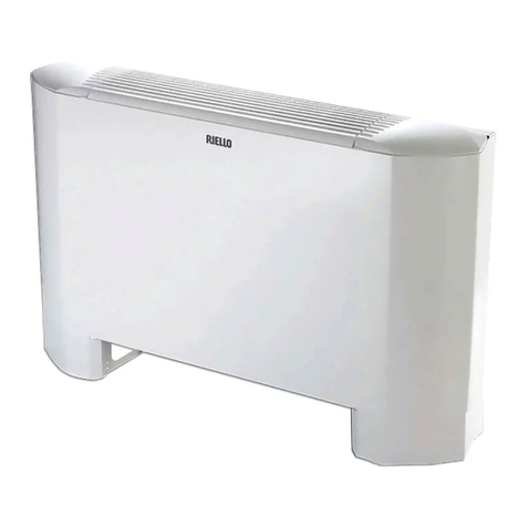
Riello DESIGN WALL Series User guide

Cod. Doc-0079285 rev. 7 11/2019
DESIGN WALL
IT ISTRUZIONI PER L’INSTALLATORE E PER IL SERVIZIO TECNICO DI ASSISTENZA
EN INSTRUCTIONS FOR THE INSTALLER AND THE TECHNICAL SERVICE CENTRE


3
DESIGN WALL
Gentile Cliente,
La ringraziamo per aver preferito un prodotto RIELLO.
Con questo libretto desideriamo fornirLe le informazioni che
riteniamo necessarie per una corretta e più facile installazione,
senza voler aggiungere nulla alla Sua competenza e capacità tecnica.
Rinnovati ringraziamenti.
RIELLO S.p.A.
Conformità
L’apparecchio è conforme alle seguenti Direttive:
- Direttiva EMC 2014/30/UE
- Direttiva LV 2014/35/UE
- Direttiva RoHS 2011/65/UE
- Direttiva RAEE 2012/19/UE
Dear Customer,
Thank you for choosing a RIELLO product.
This booklet contains all the information which might be
necessary for the correct and easy installation, without
prejudice for your technical skills and knowledge.
Thanks again.
RIELLO S.p.A.
Compliance
The unit complies with the following Standards:
- EMC Directive 2014/30/UE
- LV Directive 2014/35/UE
- RoHS Directive 2011/65/UE
- WEEE Directive 2012/19/UE
Gamma Range
Modello Codice
DESIGN WALL 11 20117815
DESIGN WALL 17 20117816
DESIGN WALL 23 20117817
DESIGN WALL 11P 20117222
DESIGN WALL 17P 20117224
DESIGN WALL 23P 20117225
Model Code
DESIGN WALL 11 20117815
DESIGN WALL 17 20117816
DESIGN WALL 23 20117817
DESIGN WALL 11P 20117222
DESIGN WALL 17P 20117224
DESIGN WALL 23P 20117225
Il prodotto a ne vita non dev’essere
smaltito come un riuto solido urbano
ma dev’essere conferito ad un centro
di raccolta differenziata.
At the end of its life, the product
should be not be disposed of as solid
urban waste, but rather it should be
handed over to a differentiated waste
collection centre.

4
DESIGN WALL - Generalità / General information
Indice
In alcune parti del libretto sono utilizzati i simboli:
ATTENZIONE= per azioni che richiedono particolare
cautela ed adeguata preparazione.
VIETATO= per azioni che non devono essere
assolutamente eseguite.
Contents
The following symbols are used in this publication:
WARNING = actions requiring special care and
appropriate training.
DO NOT = actions that MUST ON NO ACCOUNT be
carried out.
1. GENERAL INFORMATION ...............................4
1.1 General notices ........................................................ 5
1.2 Fundamental safety rules ........................................... 6
1.3 General description................................................... 6
1.4 Technical Tag.............................................................7
1.5 Technical data .......................................................... 8
1.6 Dimensions.............................................................. 9
1.7 Dimensions and weight during transportation ............... 9
1.8 ChartsofWaterow-Pressuredrop ............................ 9
1.9 Wiring diagrams....................................................... 10
2. INSTALLATION........................................... 12
2.1 Receiving thr product ................................................12
2.2 Unit placement.........................................................12
2.3 Installation procedure ...............................................12
2.4 Rear view ................................................................13
2.5 Installation clearances...............................................13
2.6 Opening of aesthetic parts for installation ......................... 14
2.7 Wall mount ............................................................. 16
2.8 Hydraulic connections .............................................. 18
2.9 Condensate drain..................................................... 19
2.10 Wiring.....................................................................21
2.11 Filling the plant ....................................................... 22
2.12 Airexhaustwhenllingthesystem............................. 22
3. USE...................................................... 23
3.1 Managing the appliance with the remote control .......... 23
3.2 Management of the appliance with the touch-screen
display................................................................... 23
3.3 Symbols legenda ............................................................24
3.4 Description of operation..................................................25
3.5 Management of the appliance with the CP D35 remote
control accessory .....................................................28
3.6 Appliance management ............................................29
4. MAINTENANCE......................................... 30
4.1 Maintenance ........................................................... 30
4.2 External cleaning .....................................................30
4.3 Cleaningtheairsuctionlters ................................... 31
5. TROUBLESHOOTING................................... 32
5.1 Alarms ................................................................... 32
5.2 Troubleshooting....................................................... 33
1. GENERALITA’ .............................................4
1.1 Avvertenze generali ................................................... 5
1.2 Regole fondamentali di sicurezza ................................ 6
1.3 Descrizione generale ................................................. 6
1.4 Targhetta Tecnica .......................................................7
1.5 Dati tecnici .............................................................. 8
1.6 Dimensioni .............................................................. 9
1.7 Dimensioni e pesi in trasporto .................................... 9
1.8 Graciportata-Perditedicarico ................................ 9
1.9 Schemi elettrici ....................................................... 10
2. INSTALLAZIONE ......................................... 12
2.1 Ricevimento del prodotto ...........................................12
2.2 Posizionamento dell’unità..........................................12
2.3 Modalità d’installazione.............................................12
2.4 Vista posteriore ........................................................13
2.5 Distanze minime di installazione.................................13
2.6 Apertura parti estetiche per installazione .......................... 14
2.7 Installazione a parete............................................... 16
2.8 Collegamenti idraulici ............................................... 18
2.9 Scarico condensa ..................................................... 19
2.10 Collegamenti elettrici.................................................21
2.11 Riempimento impianto ............................................. 22
2.12 Evacuazione dell’aria durante il riempimento
dell’impianto .......................................................... 22
3. USO ..................................................... 23
3.1 Gestione dell’apparecchio con il telecomando .............. 23
3.2 Gestione dell’apparecchio con il display touch-screen ... 23
3.3 Legenda simboli ...................................................... 24
3.4 Descrizione del funzionamento .................................. 25
3.5 Gestione dell’apparecchio con l’accessorio comando a
parete CPD 35 ..........................................................28
3.6 Utilizzo dell’apparecchio ...........................................29
4. MANUTENZIONE....................................... 30
4.1 Manutenzione .........................................................30
4.2 Pulizia esterna ........................................................ 30
4.3 Pulizialtriaspirazionearia ...................................... 31
5. ALLARMI, ANOMALIE E RIMEDI ..................... 32
5.1 Visualizzazione allarmi.............................................. 32
5.2 Anomalie e rimedi ................................................... 33

5
DESIGN WALL - Generalità / General information
1.1 Avvertenze generali
L’installazione degli apparecchi RIELLO deve essere
effettuata da impresa abilitata ai sensi della Legge
D.M.37/2008che,anelavoro,rilascialproprietariola
dichiarazione di conformità di installazione realizza-
ta a regola d’arte, cioè in ottemperanza alle Norme
vigenti ed alle indicazioni fornite in questa pubblica-
zione.
È esclusa qualsiasi responsabilità contrattuale ed ex-
tracontrattuale di RIELLO per danni causati a persone,
animali o cose, da errori di installazione, di regolazio-
ne e di manutenzione, o da usi impropri.
In caso di funzionamento anomalo, o fuori uscite di
liquidi, posizionare l’interruttore generale dell’impian-
to su “spento” e chiudere i rubinetti di intercettazione.
Chiamare con sollecitudine il Servizio Tecnico di
Assistenza RIELLO, oppure personale professionalmente
qualicato.
Non intervenire personalmente sull’apparecchio.
Questa pubblicazione deve essere conservata con cura
perché è parte integrante dell’apparecchio e dovrà
SEMPRE accompagnarlo anche in caso di cessione ad
altro proprietario o utente, o di trasferimento ad altro
impianto.
In caso di danneggiamento o smarrimento richiedere
un’altra copia al Servizio Tecnico di Assistenza RIELLO di
zona.
Gli interventi di riparazione o manutenzione devo-
no essere eseguiti dal Servizio Tecnico di Assistenza
RIELLO, o da personale qualicato, secondo quanto
previsto nella presente pubblicazione.
Non modicare o manomettere l’apparecchio in
quanto si possono creare situazioni di pericolo ed il
costruttore dell’apparecchio non sarà responsabile
di eventuali danni provocati.
Il non utilizzo dell’apparecchio per un lungo periodo
comporta l’effettuazione delle seguenti operazioni:
Posizionare l’interruttore generale dell’impianto su
“spento”.
Chiudere i rubinetti dell’acqua.
Se c’è pericolo di gelo, accertarsi che l’impianto sia
stato addizionato con del liquido antigelo, altrimenti
vuotare l’impianto.
Nelle operazioni di installazione e/o manutenzione
utilizzare abbigliamento e strumentazione idonei ed
antinfortunistici.
RIELLO declina qualsiasi responsabilità per la
mancata osservanza delle vigenti norme di sicurezza e
di prevenzione degli infortuni.
Rispettare le leggi in vigore nel Paese in cui viene
installata la macchina, relativamente all’uso e allo
smaltimento dell’imballo, dei prodotti impiegati per
puliziaemanutenzione,eperlagestionedelnevita
dell’unità.
1.1 General notices
All RIELLO equipment shall be installed by skilled
operators, authorised by Law D.M. 37/2008, who
shall issue a declaration of conformity for the state-
of-the-art installation, that is to say, an installation
carried out pursuant to the current Legislation and the
instructions in this booklet.
Any contractual and tortious liability of RIELLO’s for
damages to property or people or animals because of
installation, calibration and maintenance mistakes or
erroneous usage of the equipment is excluded.
In case of abnormal operation, or leaks of liquids,
position the main switch of the system in the “off”
position and close the stop taps.
Call RIELLO’s Technical Service or other professionally
qualiedpersonnelimmediately.
Do not try to repair the unit.
This booklet must be kept carefully as it is an integral
part of the equipment and must ALWAYS be present,
including in case of sale of the equipment to another
owner or user, or of transfer to another system.
Should the manual get damaged or lost, please ask for a
duplicate manual from the RIELLO’s Technical Service.
Repairs or maintenance actions must be carried out
by RIELLO’s Technical Service staff or other skilled staff,
pursuant to the provisions of this publication.
Do not modify or tamper with this equipment, as doing
so might cause dangerous situation, for which the
manufacturer waives all liability.
If the device is to remain out of service for a prolon-
ged period, make sure you carry out the following
operations:
Set the main system switch to "Off".
Close the water taps.
If there is danger of frost, make sure that you have ad-
ded anti-freeze liquid into the circuits, or drain out the
system otherwise.
In the installation and/or maintenance operations
please adopt the appropriate attire and accident
prevention devices.
RIELLO waives all and any responsibility for failure
to observe the safety and accident prevention
regulations from time to time in force.
Comply with the legislation in force on the country of
deployment with regard to the use and disposal of
packaging, of cleaning and maintenance products and
for the management of the unit’s decommissioning.

6
DESIGN WALL - Generalità / General information
È vietato l’uso dell’apparecchio ai bambini ed alle
persone inabili non assistite.
È vietato effettuare qualsiasi intervento tecnico o di
pulizia, prima di aver scollegato l’apparecchio dalla rete
di alimentazione elettrica posizionando l’interruttore
generale dell’impianto su “spento”.
È vietato modicare i dispositivi di sicurezza o di
regolazione senza l’autorizzazione e le indicazioni del
costruttore dell’apparecchio.
È vietato salire con i piedi sull’apparecchio, sedersi e/o
appoggiarvi qualsiasi tipo di oggetto.
È vietato tirare, staccare, torcere i cavi elettrici
fuoriuscenti dall’apparecchio anche se questo è
scollegato dalla rete di alimentazione elettrica.
È vietato spruzzare o gettare acqua direttamente
sull’apparecchio.
È vietato disperdere, abbandonare o lasciare alla
portata di bambini il materiale dell’imballo, potenziale
fonte di pericolo.
È vietato assolutamente toccare le parti in
movimento, interporsi tra le stesse, o introdurre
oggetti appuntiti attraverso le griglie.
È vietato toccare l’apparecchio se si è a piedi nudi e/o
con parti del corpo bagnate o umide.
L’apparecchio può raggiungere temperature superiori
ai 70°C in alcuni punti.
Do not allow children or unassisted disabled people to
use the unit.
It is forbidden carry out technical or cleaning activities
before disconnecting the unit from the power grid by
positioning the system’s main switch in the “off” position.
It is forbidden to modify the safety or regulation
devices without the authorisation and directions of the
manufacturer.
Do not stand, sit and/or place objects on the unit.
Do not pull, detach or twist the electrical wires
coming out of the unit, even when the unit is
disconnected from the power grid.
Do not spray or throw water directly on the unit.
Do not dispose of, abandon or leave the potential-
ly hazardous packaging materials within the reach of
children.
It is strictly forbidden to touch any moving parts, in-
terfere with them or introduce pointed objects through
the grids.
Do not touch the unit while barefoot and/or partially
wet.
The device can reach temperatures of more than 70 °C
in some parts.
1.2 Regole fondamentali di sicurezza 1.2 Fundamental safety rules
1.3 Descrizione generale 1.3 General description
Terminale idronico a vista (RAL 9003) per impianti a
2 tubi caldo/freddo pensato a completamento
dell’offerta RIELLO con taglie che vanno da una potenza
di 1,1 kW a 2,3 kW frigoriferi con una profondità pari a soli
128 mm.
Disponibile in due versioni:
- Con interfaccia touch screen sul pannello frontale
dell’unità e telecomando ad infrarossi a corredo:
La scheda elettronica a bordo macchina prevede un
contatto pulito per ON/OFF remoto
DESIGN WALL 11
DESIGN WALL 17 TELECOMANDO INCLUSO
DESIGN WALL 23
Visible hydronic system (RAL 9003) for circuits with
2 hot/cold pipes designed to complement the RIELLO
range with sizes from 1.1 kW to 2.3 kW cooling capacity with
a depth of just 128 mm.
Available in two versions:
- With touch screen interface on the front panel of the
unit and infrared remote control supplied:
The electronic circuit board on the machine has a volt-
free contact for remote ON/OFF
DESIGN WALL 11
DESIGN WALL 17 REMOTE CONTROL SUPPLIED
DESIGN WALL 23

7
DESIGN WALL - Generalità / General information
- Con pannello frontale liscio senza interfaccia touch
screen e scheda elettronica per comando remoto a
parete.
ACCESORIO
DESIGN WALL 11P
COMANDO REMOTO
DESIGN WALL 17P CPD35
DESIGN WALL 23P
Gli attacchi idraulici sono sempre a destra nella versione a
catalogo e non sono invertibili.
1.4 Targhetta Tecnica 1.4 Technical Tag
La targhetta tecnica riporta i dati tecnici e prestazionali
dell’apparecchio. In caso di smarrimento richiederne
un duplicato al Servizio Tecnico di Assistenza RIELLO.
La manomissione, l’asportazione, la mancanza
della Targhetta Tecnica o quant’altro non permetta la
sicura identicazione del prodotto, rende difcoltosa
qualsiasi operazione di installazione e manutenzione.
The technical tag shows all technical and performance
data of the unit. Should the tag get lost, please ask for
a duplicate tag from the RIELLO’s Technical Service.
Any tampering with, the removal or the lack of the
Technical Tag or of any other element whose absence
preventscertainidenticationoftheproductmakesit
moredifculttoinstallandmaintaintheproduct.
- With smooth front panel, no touch screen
interface and electronic circuit board for wall mounted
remote control.
CPD35
DESIGN WALL 11P
REMOTE CONTROL
DESIGN WALL 17P ACCESSORY
DESIGN WALL 23P
The hydraulic connections are always on the right in the
catalogue version and cannot be reversed.
RIELLO S.p.A. -
37045 Legnago (VR) Made in Italy
Type
COD.
Power Input W
Frequency Hz
CFG.
Voltage V
Current cons. A
Matr.
Max pressure bar

8
DESIGN WALL - Generalità / General information
1.5 Dati tecnici 1.5 Technical data
11 - 11P 17 - 17P 23 - 23P
Resa in raffreddamento totale (a)
Total cooling capacity (a) kW 1,14 1,62 2,34
Resa in raffreddamento sensibile
Sensible cooling capacity kW 0,84 1,4 2,1
Portata d’acqua
Waterowrate l/h 196 279 402
Perdita di carico
Water pressure drops kPa 10,7 4,5 2,1
Resa in riscaldamento 50°C (b)
Heating capacity 50°C (b) kW 1,61 2,35 3,25
Portata d’acqua (50°C)
Waterowrate(50°C) l/h 196 279 402
Perdite di carico (50°C)
Water pressure drops (50°C) kPa 8,8 3,4 3,5
Resa in riscaldamento (70°C) (c)
Heating capacity (70 °C) (c) kW 2,78 4,12 5,72
Portata d’acqua (70°C)
Waterowrate(70°C) l/h 239 354 492
Perdite di carico (70°C)
Water pressure drops (70°C) kPa 13 4,7 4,5
Contenuto d’acqua batteria
Coil water content l 0,54 0,74 0,93
Massima pressione d’esercizio
Maximum operating pressure bar 10 10 10
Raccordi per tubi dell’acqua
Waterpipettings inch EUROKONUS 3/4" EUROKONUS 3/4" EUROKONUS 3/4"
Portata d’aria max
Airowratemax m3/h 320 430 540
Portata d’aria med.
Airowratemed m3/h 250 340 410
Portata d’aria min.
Airowratemin m3/h 140 230 310
Tensione di alimentazione
Supply voltage V/ph/Hz 230/1/50 230/1/50 230/1/50
Potenza assorbita alla portata d’aria massima
Powerinputatmaximumairow W 12 14 18
Potenza assorbita alla portata d’aria minima
Powerinputatminimumairow W 4,8 5,1 5,8
Pressione sonora alla massima portata d’aria (d)
Soundpressureatmaximumairow(d) dB(A) 39,7 42,4 42,6
Pressione sonora alla minima portata d’aria (d)
Soundpressureatminimumairow(d) dB(A) 24,9 25,2 25,8
Massima temperatura ingresso acqua
Maximum water inlet temperature °C 80 80 80
Minima temperatura ingresso acqua
Minimum water inlet temperature °C 4 4 4
Peso
Weight Kg 14 16 19
(a) aria 27°C bs 19°C bu; acqua 7°C ingresso 12°C uscita
(b) aria 20°C; acqua 50°C ingresso. Flusso come nel raffreddamento
(c) aria 20°C; acqua 70°C ingresso 60°C uscita
(d) Pressione sonora misurata in camera semianecoica secondo la
normativa ISO 7779
(a) air 27°C db 19°C wb ; water 7°C in 12°C out
(b) air 20°C ; water 50 °C in. Flow as in cooling
(c) air 20°C ; water 70°C in 60 °C out
(d) Sound pressure measured in a semi anechoic chamber according to
ISO 7779

9
DESIGN WALL - Generalità / General information
1.6 Dimensioni 1.6 Dimensions
Modello L
11 - 11P 902 mm
17 - 17P 1102 mm
23 - 23P 1302 mm
Model L
11 - 11P 902 mm
17 - 17P 1102 mm
23 - 23P 1302 mm
1.8 Graciportata-Perditedicarico 1.8 ChartsofWaterow-Pressuredrop
Perdita di carico [kPa]
Pressure drop [kPa]
Portata d’acqua [kg/h]
Water flow [kg/h]
11 17 23
0,5
1
2
4
8
16
30 150 750
1.7 Dimensioni e pesi in trasporto 1.7
Dimensions and weight
during
transportation
11 - 11P 17 - 17P 23 - 23P
kg 15 17 20
L mm 1.035 1.235 1.435
H mm 490 490 490
P mm 213 213 213
L
P
H

10
DESIGN WALL - Generalità / General information
1.9 Schemi elettrici 1.9 Wiring diagrams
H2 sonda temperatura acqua
M1 motore ventilatore DC inverter
Y1 collegamento valvola a 2 vie motorizzata (uscita
in tensione a 230V/ 50Hz 1A)
L-N collegamento alimentazione elettrica 230V/50Hz
CP ingresso sensore presenza (se aperto, il ventil-
convettore viene posto in stand-by.)
AIR sonda aria
DISPLAY cablaggio display pannello
SW
collegamento motore per orientamento diffusore
H2 water temperature probe
M1 fan motor DC inverter
Y1 connection for 2 way motorized valve (230V/50Hz
1A powered output)
L-N 230V/50Hz electrical power supply connection
CP presence sensor input (if opened, the fan coil
goes into stand-by.)
AIR air probe
DISPLAY control panel (display) wiring
SW connection to the motor for the diffuser swing
⏚
SWY1
CP
M1
L N
DISPLAY
AIR
H2
Scheda di controllo dell’unità con telecomando Circuit board for remote control unit

11
DESIGN WALL - Generalità / General information
Scheda di controllo dell’unità con comando a parete
CPD35
-AB+ Collegamento seriale per comando remoto a
muro CPD 35 (rispettare la polarizzazione AB)
H2
Sonda temperatura acqua. Se la sonda è colle-
gata, la sua presenza viene rilevata dalla scheda
quando si dà tensione; l’avvio avviene rispettan-
do le soglie di minima temperatura dell’acqua
in riscaldamento (30°C) e massima temperatura
dell’acqua in raffrescamento (20°C). E’ possibile
il funzionamento privo di sonda, nel qual caso
vengono ignorate le soglie suddette.
M1 motore ventilatore DC inverter
Y1 Collegamento valvola a 2 vie motorizzata (uscita
in tensione a 230V/ 50Hz 1A)
L-N Collegamento alimentazione elettrica 230V/50Hz
BO Uscita consenso caldaia (contatto pulito max 1A)
CH Uscita consenso refrigeratore (contatto pulito
max 1A)
CP Non utilizzato
AIR (*) Sonda aria opzionale
SW Motore per orientamento diffusore
*Collegare in alternativa alla sonda aria del
controllo a muro CPD 35
Circuit board for unit with CPD35 wall-mounted control
-AB+ Serial connection for wall-mounted remote con-
trol CPD 35 (respect the AB polarisation)
H2
Water temperature probe. The circuit board de-
tects the temperature probe if it’s connected.
The unit turns if the water temperature is gra-
ter than minimum water temperature in heating
mode (30°C) or if it’s lower than maximum water
temperature in cooling mode (20°C). The unit can
work without the probe but the minimum water
temperature in heating and the maximum water
temperature in cooling are not considered.
M1 Fan motor DC inverter
Y1 connection for 2 way motorized valve (230V/50Hz
1A powered output)
L-N 230V/50Hz electrical power supply connection
BO Boiler go-ahead output (free contact max 1A)
CH Chiller go-ahead output (free contact max 1A)
CP Not used
AIR (*) Optional air probe
SW Connection to the motor for the diffuser swing
*Connect as an alternative to the air probe of the
CPD 35 wall-mounted control panel
BO CH
INN-FR-B30
EV2 NEV1 N
LED
H4
H2
AIR
COMM M1
MOTOR
LN
NL
Y1
H2
S1
Y2
GRIDCP
BOILER CHILLER
AIR*
BA
ON
DCASCII
RTU
-A B +
- AB+
SW
CN1 CN2
La scheda va collegata al comando remoto a muro CPD 35:
un termostato elettronico (dotato di sonda di temperatura
opzionalmente remotizzabile in uno dei fancoils ad esso
collegati) con possibilità di controllo su uno o più appa-
recchi(noadunmassimodi30).
Per le informazioni relative al CPD 35 consultare il foglio
istruzioni allegato al componente.
The card must be connected to the command wall-
mounted CPD 35: an electronic thermostat (tted
with temperature probe optionally remotable in one
of the fancoils connected to it) with the possibility of
controlling one or more cooler-convector/cooler-radiators
(up to a maximum of 30).
ForinformationontheCPD35seetheinstructionleaet
supplied with the component.

12
DESIGN WALL - Installazione / Intallation
2.2 Posizionamento dell’unità
Evitare l’installazione dell’unità in prossimità di:
- posizioni soggette all’esposizione diretta dei raggi
solari;
- in prossimità di fonti di calore;
- in ambienti con tassi di umidità molto elevati e zone
con probabile contatto con l’acqua;
- in ambienti con vapori d’olio
- in ambienti sottoposti ad alte frequenze.
Accertarsi che:
- la parete su cui si intende installare l’unità abbia
una struttura e una portata adeguata;
- la zona della parete interessata non sia percorsa
da tubazioni o linee elettriche
- la parete interessata sia perfettamente in piano;
- sia presente un’area libera da ostacoli che
potrebbero compromettere la circolazione dell’aria
in ingresso ed uscita;
- la parete di installazione sia possibilmente una
parete di perimetro esterno per consentire lo
scarico della condensa all’esterno;
-il usso dell’aria non sia rivolto direttamente
verso le persone.
2.3 Modalità d’installazione
Per ottenere una buona riuscita dell’installazione e
prestazioni di funzionamento ottimali, seguire
attentamente quanto indicato nel presente manuale.
La mancata applicazione delle norme indicate, che
può causare mal funzionamenti delle apparecchiature,
sollevano la ditta RIELLO da ogni forma di garanzia e
da eventuali danni causati a persone, animali o cose.
2.2 Unit placement
Avoid installing the unit near:
- areas exposed to direct sunlight;
- heat sources;
- in environments with very high humidity and areas
in which the unit can come into contact with water;
- in environments with oil mists;
- in environments subject to high frequencies.
Make sure that:
- the wall on which you intend to install the unit has
an appropriate structure and capacity;
- the wall surface is not crossed by pipelines or power
lines;
- the wall is perfectly level;
- there are no obstructions nearby that could
compromisetheinletandoutletairow;
- the wall on which you are installing the unit is (if
possible) an external perimeter wall, in order to
allow condensate drain outside the premises;
-airowisnotdirectedtowardsby-standers.
2.3 Installation procedure
For ideal installation and performance levels,
carefully follow the instructions in the manual.
Failure to do so may cause system malfunctions and
automatically voids the warranty, and relieves RIELLO
of any harm caused to persons, animals or property.
2.1 Ricevimento del prodotto
Dopo aver tolto l’imballo assicurarsi dell’integrità e
della completezza del contenuto. In caso di necessità
rivolgersi all’Agenzia che ha venduto l’apparecchio.
Materiale a corredo:
- Dima di installazione in cartoncino
- 2xStaffedissaggioaparete
- Manuale di installazione
- 6 x etichette di garanzia e ricambi
- Telecomando con una batteria al litio secco CR2015 3V
(telecomando non fornito con i modelli 11P, 17P e 25P)
- 2 adattatori Eurokonus 3/4”
2.1 Receiving thr product
Check the integrity and completeness of the supplied
equipment as soon as you take it out of its packa-
ging. If necessary, consult the Agency that sold you the
equipment.
Material supplied:
- Cardboard installation template
- 2 x Wall mounting brackets
- Installation manual
- 6 x warranty and spare part labels
- Remote control with CR2015 3V dry lithium battery (re-
mote controller not supplied with models 11P, 17P e 25P)
- 2 Adapters 3/4 “to Eurokonus

13
DESIGN WALL - Installazione / Installation
2.4 Vista posteriore 2.4 Rear view
A
B
C
D
A
E
F
A) Staffassaggioamuro
B) Uscita acqua batteria
C) Ingresso acqua batteria
D) Uscita scarico condensa
E) Morsettiera di collegamento
F) Fissacavo
A) Wall mounting bracket
B) Coil water inlet
C) Coil water outlet
D) Condensate drain
E) Connector terminal
F) Cable clamp
20 mm 20 mm
120 mmmin. 2000 mm
pavimento/floor
2.5 Distanze minime di installazione
Nella gura sono indicate le distanze minime di
montaggio del ventilconvettore da pareti e mobili
presenti nell’ambiente.
2.5 Installation clearances
Thegureshowstheminimumdistancesrequiredofthe
cooler-radiator from the walls and furniture on site.

14
DESIGN WALL - Installazione / Intallation
2.6 Apertura parti estetiche per installazione
Per le descrizioni fare riferimento alle immagini illustrate
di seguito.
1 Rimuovereianchettislandoliversol'alto;
2 Rimuovere le sei viti a testa esagonale presenti ai lati
del pannello frontale per poter rimuovere il pannello
frontale estetico;
A FIANCHETTI
B PANNELLO FRONTALE ESTETICO
2.6 Opening of aesthetic parts for installation
For descriptions refer to the images shown below.
1 Remove the side panels by unthreading them upwards;
2 Remove the six hex screws on the side of the front
panel to remove the aesthetic front panel;
A SIDE PANELS
B AESTHETIC FRONT PANEL
A
B
A
B
1
2

15
DESIGN WALL - Installazione / Installation
3 Ruotareiltriesollevarli;
4 Rimuovere la vite di ssaggio dei anchi e sollevarli
verso l’alto rimuovendo prima le due viti che ssano
alancosinistrolastrutturadeldisplay,sepresente.
A FILTRI
B FIANCHI LATERALI
3 Wheelsandrisethelters;
4 Remove the xing screws of side panels and the two
screwsthatxtotheleftpanelthedisplayframework,
if present; lift the panels upwards.
A FILTERS
B SIDE PANELS
A
BB
3
4

16
DESIGN WALL - Installazione / Intallation
2.7 Installazione a parete
- Per un'agevole installazione, soprattutto se si
vuole predisporre l'impianto in attesa della posa
denitivadell'apparecchio,consigliamolapredisposi-
zionediunacassettaadincassocomedagura;
- Se l'installazione denitiva non viene effettuata al
momento dell'installazione della cassetta lasciare
lunghe le tubazioni idriche e di scarico condensa in
modo da poterle poi raccordare senza giunzioni;
- Al momento dell'installazione sarà possibile allaccia-
re il ventilconvettore mediante raccordo 90° e
tronchetto con raccordo Eurokonus;
- In alternativa, se si riesce a curvare in modo agevole
la tubazione (dipenderà dalla profondità della
cassetta installata), sarà possibile installare
direttamente il raccordo Eurokonus nella tubazione;
- Fare attenzione all'inclinazione del tubo di scarico
condensa, che deve essere appoggiato sul fondo della
cassetta nella parte più bassa in modo che l'altezza
del tubo non superi mai l'altezza dell'attacco di
scarico del ventilconvettore;
- Per la quota di installazione fare riferimento alla dima
di installazione in dotazione riportata
successivamente.
A CASSETTA DA INCASSO
B TUBAZIONI IDRONICHE DI RACCORDO
C TUBO DRENAGGIO CONDENSA
2.7 Wall mount
- For smooth installation, especially if you want to
set-up the system before you install the device, we
recommend installing a built-in cistern, as shown in
thegure;
- If you do not complete installation of the device
when installing the cistern, leave the water and
condensate drain pipes hanging loose, so that you
can later make the connections without joints;
- Whenyounallyinstallthedevice,itwillbepossibleto
connect the cooler-radiator with a 90° tting and
socket with Eurokonus connection;
- another option if you can comfortably bend the
pipeline (which will depend on the depth of the
installed cistern) is to install the Eurokonus connection
inside the pipeline;
- pay attention to the tilt angle of the condensate drain
pipe, which must rest be laid on the lowermost part
of the cistern so that the pipe’s height never exceeds
the height of the cooler-radiator drain connection;
- for the installation heights, refer to the installation
template supplied with the device and which is
shown successively.
A BUILT-IN CISTERN
B CONNECTING WATER PIPELINES
C CONDENSATION DRAINAGE PIPE
A
B
C

17
DESIGN WALL - Installazione / Installation
1 Utilizzare la dima in cartoncino.
Tracciare sulla parete la posizione delle due staffe di
ssaggioavendocuradipiegareladimaaseconda
della lunghezza dell’unità seguendo le istruzioni
riportate sulla dima stessa.
2 ForareconunapuntaadeguataedinlareitasselliA(2
perognistaffa); ssare le duestaffeB. Non stringere
eccessivamente le viti, in modo da poter effettuare una
regolazione delle staffe con una bolla di livello.
3 Bloccare denitivamente le due staffe serrando
completamente le quattro viti.
4 Vericarne la stabilità spostando manualmente le
staffe verso destra e sinistra, alto e basso.
Montare l’unità, vericando il corretto aggancio sulle
staffe e la sua stabilità.
Fare molta attenzione all’inclinazione dell’unità: se in-
stallato in modo perfettamente orizzontale, la penden-
za della vaschetta raccogli condensa assicura il corretto
deussodell’acquaversoloscarico.L’installazionedel
ventilconvettore con inclinazione verso sinistra (vedi
guraafondopagina)èassolutamentevietata.
1
3
2
4
G
NO
1 Use the paper template shown in full scale.
Trace the position of the two fixing brackets
onthewallwithcaretobendthetemplatedepending
onthelengthoftheunit;seetheinstructionsonthe
template.
2 Drill a hole using a proper tip and insert the plugs A(2
per bracket) then attach the two brackets B. Do not
over-tighten the screws so that you can adjust them
with a spirit level.
3 Firmly fasten the brackets by tightening the four screws.
4 Check stability by moving the brackets to the right and
left, up and down.
Assemble the unit, making sure it fastens properly onto
the brackets and that it is stable.
Pay close attention to the inclination of the unit: if in-
stalled in a perfectly horizontal manner, the slope of
thecondensatecollectiontrayprovidesthecorrectow
of water to the drain. Installation of the fan coil with a
tilttotheleft(seegureatthebottomofthepage)is
strictly prohibited.
A AB

18
DESIGN WALL - Installazione / Intallation
2.8 Collegamenti idraulici
11 - 11P 17 - 17P 23 - 23P
TUBAZIONI: rame - Eurokonus 3/4” GAS
PIPELINE: copper - Eurokonus 3/4” GAS mm 14 16 18
2.8 Hydraulic connections
A
A Adattatore Eurokonus
La scelta ed il dimensionamento delle linee idrauliche
è demandato per competenza al progettista, che dovrà
operare secondo le regole della buona tecnica e delle le-
gislazioni vigenti.
Per effettuare i collegamenti:
Posizionare le linee idrauliche
Serrare le connessioni utilizzando il metodo “chiave
contro chiave”
Vericarel’eventualeperditadiliquido
Rivestire le connessioni con materiale isolante
In dotazione all’apparecchio vi sono due adattatori piani
per trasformare gli attacchi 3/4” Eurokonus in 3/4” GAS.
Inquestocaso perlatenutaidricadelleconnessioni-
lettate utilizzare canapa e pasta verde; l’utilizzo di nastro
diteonèconsigliatoinpresenzadiliquidoantigelonel
circuito idraulico
Le linee idrauliche e le giunzioni devono essere isolate
termicamente.
Evitare isolamenti parziali delle tubazioni.
Evitare di stringere troppo per non danneggiare l’isola-
mento.
A Eurokonus adapter
The choice and sizing of the hydraulic lines must be made
by an expert who must operate according to the rules of
good technique and the laws in force.
Position the hydraulic lines
Tighten the connections using the “spanner and counter
spanner” method
Check for any leaks of liquid
Coat the connections with insulating material.
Accompanying this unit there are two adapters to tran-
sform the 3/4” Eurokonus connections in 3/4” BSP. In this
case use hemp and green paste or similar to seal the thre-
adedconnections;theuseofTeonisadvisedwhenthere
is anti-freeze in the hydraulic circuit.
The hydraulic lines and joints must be thermally insulated.
The hydraulic lines and joints must be thermally insu-
lated.
Avoid partially insulating the pipes.
Do not over-tighten to avoid damaging the insulation.

19
DESIGN WALL - Installazione / Installation
2.9 Scarico condensa
La rete di scarico della condensa deve essere opportuna-
mente dimensionata (diametro interno tubo minimo 14
mm) e la tubazione posizionata in modo da mantenere
sempre lungo il percorso una determinata pendenza, mai
inferiore a 1%. Il tubo di scarico si collega direttamente
alla vaschetta di scarico, posizionata in basso sulla spalla
laterale, sotto gli attacchi idraulici.
- Se possibile fare deuire il liquido di condensa
direttamente in una grondaia o in uno scarico di
“acque bianche”.
- In caso di scarico nella rete fognaria, si consiglia di
realizzare un sifone per impedire la risalita dei cattivi
odori verso gli ambienti. La curva del sifone deve essere
più in basso rispetto alla bacinella di raccolta
condensa.
- Nel caso si debba scaricare la condensa all’interno di
un recipiente, questo deve restare aperto all’atmosfera
ed il tubo non deve essere immerso in acqua, evitando
fenomeni di adesività e contropressioni che
ostacolerebberoilliberodeusso.
- Nel caso si debba superare un dislivello che
ostacolerebbeildeussodellacondensa,ènecessario
montare una pompa.
Tali pompe si trovano comunemente in commercio.
E’ comunque opportuno, al termine dell’installazione,
vericare il corretto deusso del liquido di condensa
versando molto lentamente (circa 1/2 l di acqua in circa
5-10 minuti) nella vaschetta di raccolta.
2.9 Condensate drain
The condensate drain network must be sized appro-
priately (minimum inner pipe diameter: 14 mm) and the
pipeline positioned so that it maintains a consistent
slope along the line (never less than 1%). The drain pipe
connects directly to the drain pan installed at the bottom
on the side panel under the hydraulic connections.
- If possible, make the condensate liquid ow directly
onto a gutter or into a "white waters" drain.
- If the liquid is discharged into a sewer, we recommend
that you install a trap-vent to prevent bad odours from
rising back up into the building. The curve of the trap
must be lower than the condensate tray.
- If you need to drain the condensate into a container, it
must remain open and the pipe must not be
immersed in water to prevent adhesion and
back-pressurethatwouldobstructfreeow.
- If the drain pipe has to overcome a gap in height due to
its particular installation which would obstruct
condensateow,remembertoinstallapump.
These pumps are commonly available on the market.
However, it is advisable that after installing the pump you
checkproperowofthecondensateliquid,pouringitin
very slowly (about 1/2 l of water in about 5-10 minutes)
into the drain pan.

20
DESIGN WALL - Installazione / Intallation
Montaggio del tubo di scarico della condensa
Collegare al raccordo di scarico della vaschetta raccogli
condensauntuboperildeussodelliquidobloccandolo
inmodoadeguato.Vericarechelaprolungarompigoccia
sia presente e correttamente installata.
A RACCORDO DI SCARICO
B TUBO SCARICO CONDENSA
Condensate drain pipe assembly
Connect the drain connection of the drain pan that
collects the condensate uid to a hose and tighten it
properly. Make sure the drip-guard extension is present
and that it has been properly installed.
A DRAIN CONNECTION
B LIQUID DRAIN PIPE
A
B
ø 14 mm
Fare attenzione all'inclinazione del tubo di scarico
condensa quandoviene convogliato all'esterno come in
gura.
A VENTILCONVETTORE
B TUBO SCARICO CONDENSA
Pay attention to the tilt of the condensate drain pipe when
it channels condensate outside the premises as shown in
thegure.
A FAN COIL
B CONDENSATE DRAIN PIPE
A
B
This manual suits for next models
13
Table of contents
Other Riello Heater manuals