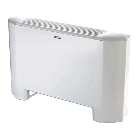
Riello HELOTERM Series User manual

HELIOTERM INVERTER
1Doc-0091342 Rev. 0
PT
Avisos preliminares
Montagem e ligações do controlo do
ventilador para regulação remota
Estas instruções são parte integrante do manual do aparelho
no qual o KIT é instalado. Consulte este manual para as
ADVERTÊNCIAS GERAIS e REGRAS FUNDAMENTAIS DE SEGURANÇA.
Montado a bordo da máquina, permite gerir o motor, com
velocidades modulantes. A regulação do motor pode ser
efetuada através de uma entrada analógica de 0-10 V DC
com impedância de entrada de 25kΩ.
Para as saídas de comando para a placa, este valor de
impedância deve ser tido em conta, especialmente, no
caso do comando de várias unidades em paralelo.
Possui uma saída de 230 V para o comando da eletroválvula.
CDI 15 - PLACA DE CONTROLO PARA LIGAÇÃO
REMOTA 0-10
Versões
Códigos
20116413
CDI 15 - Placa de controlo para ligação remota 0-10
Em algumas partes do manual são utilizados os símbolos:
ATENÇÃO = para ações que exigem cautela especial
e preparação adequada.
PROIBIDO = para ações que não devem
absolutamente ser executadas.
EN
Preliminary instructions
Mounting and connecting the fan control
for remote adjustment
This instruction booklet is an integral part of the manual
of the device on which you install the kit. In that manual,
please refer to the WARNINGS and the BASIC SAFETY RULES.
Mounted on board it can control the motor; with modular
speed; the motor regulation can be done through a 0-10 V
DC analogue with 25kΩinput impedance.
Consider this impedance value for the control outputs,
especially if you want to control several units in parallel.
It has a 230 V output for driving solenoid.
CDI 15 - CONTROL CARD FOR REMOTE
CONNECTION 0-10
Versions
Codes
20116413
CDI 15 - Control card for remote connection 0-10
The following symbols are used in this publication:
WARNING = actions requiring special care and
appropriate training.
DO NOT = actions that MUST ON NO ACCOUNT be
carried out.

HELIOTERM INVERTER
2Doc-0091342 Rev. 0
A
I
L
D
E
C
H
B
G
M
PT
Insira o painel cego na respetiva sede, na parte superior do
aparelho e xe-o com os dois parafusos fornecidos (ref.A).
Para instalar a caixa das ligações:
abra a caixa (ref.B);
insira o dente inferior na respetiva ranhura (ref.C), na
parte lateral do aparelho;
encaixe a parte superior da caixa na parte lateral (D);
xe-a com os dois parafusos fornecidos (ref.E);
xe o cabo de terra à estrutura do aparelho, utilizando o
parafuso fornecido (deve ser aplicada uma força mínima
de aberto de cerca de 2N);
no par de terminais GRID (ref.L) está presente uma
ponte que assegura o funcionamento das versões Design
Inverter e Design Inverter Plus sem microinterruptor.
Para as outras versões, remova a ponte e ligue os dois
terminais provenientes do microinterruptor de segurança
da grelha*.
ligue o engate rápido do motor (MOTOR) ao presente na
placa (ref. H);
efetue as ligações elétricas, organize as cablagens, xe
os cabos com ajuda das 3 forquilhas fornecidas (ref. F);
feche a caixa, xando os 4 parafusos (ref. G);
volte a montar o painel lateral estético do aparelho;
aperte o parafuso superior no painel cego;
coloque as tampas dos parafusos no respetivo alojamento
no painel cego;
* Para versões com ligações hidráulicas à direita, consulte
o respetivo parágrafo.
Montagem
EN
Place the control panel into its housing in the upper part
of the cooler-convector/cooler-radiator and x it with the
two supplied screws (ref. A).
To install the connection box:
open the box (ref. B);
insert the lower lug into the special slot (ref. C) on the
side of the appliance;
hook the upper part of the box to the side (ref. D);
x it with the two supplied screws (ref. E);
x the earth wire to the cooler-convector/cooler-radiator
structure using the supplied screws (the minimum force
of about 2N must be used when screwing-up);
the 2 terminals of the GRID clamp (ref. I) feature a
jumper that ensures the operation of the Design inverter
andDesign inverter Plus versions without microswitch.
For the other versions remove the jumper and connect
the two terminals from the grid safety microswitch*.
connect the rapid connector on the motor (MOTOR) to
that on the board (ref. H);
make the electrical connections, order the wiring and
x the wires using the 3 supplied clamps (ref. F);
close the box and x with the 4 screws (ref. G);
mount the aesthetic side panel on the Cooler-convector/
cooler-radiator;
tighten the upper screw on the control panel;
place the screw cover into the slot on blind panel;
* For versions with hydraulic connections on the right
refer to the relevant paragraph.
Mounting

HELIOTERM INVERTER
3Doc-0091342 Rev. 0
Y2
A B
PT
Efetue as ligações elétricas a um termóstato adequado à
nalidade, de acordo com o esquema abaixo, consultando
também as instruções de ligação contidas no termóstato.
Esquema das ligações com termóstatos/
sinais de 0-10 V DC
L-N alimentação elétrica 230 V-50 Hz
10 V entrada de comando do aparelho 0-10 V (impedância de
entrada de 25kΩ)
Y2 saída para servomotores do painel de admissão móvel
(tensão de saída de 230 V/ 50 Hz 1 A) versão Plus
Y1 eletroválvula de água (tensão de saída de 230 V/ 50 Hz 1 A)
RS Cablagem da versão Plus (ligação a efetuar pelo
instalador)
HRS sonda de água, versão Plus (2kΩ)
M1 motor do ventilador DC inverter
S1 microinterruptor de segurança da grelha
Sinalizações dos leds LED signals
O LED (L) está desligado se o sinal de entrada for inferior
a 0,9 V. Acende-se no caso de valores superiores a 1 V e
sinaliza o funcionamento normal.
Pisca muitas vezes em caso de acionamento do
microinterruptor de segurança da grelha S1 devido à
operação de limpeza do ltro.
Pisca 2 vezes + pausa para o alarme do motor (por exemplo,
bloqueio devido a corpos estranhos ou avaria no sensor de
rotação).
The LED (ref. L) is off if the input signal is below 0,9 V. It
is switched on for values over 1 V and signals standard
operation.
Flashes frequently if the S1 grill safety microswitch is
enabled due to a lter cleaning operation.
2 ashes + pause for motor allarm (for example jamming
due to foreign bodies or fault in the rotation sensor).
EN
Make the electrical connections to a suitable thermostat
for this purpose according to the wiring diagram below
referring also to the connection instructions contained
into the thermostat box.
Diagram for connections with thermostats/
signals 0-10 V DC
L-N 230V-50Hz electric power supply
10V device pilot input 0-10 V (input impedance 25kΩ)
Y2 output for servomotor mobile aspiration panel
(230V/50Hz 1A powered output) Plus version
Y1 water electrovalve (outlet with a voltage of 230V/50Hz
1A)
RS Plus version wiring (to be connnected by the installer)
HRS Plus version probe (2kΩ)
M1 inverter DC fan motor
S1 grid safety microswitch

HELIOTERM INVERTER
4Doc-0091342 Rev. 0
Conguração da função de velocidade
máxima de ventilação de ar Setting maximum fan speed function
O microinterruptor A está congurado em OFF: a função de
velocidade máxima é às 1400 rpm (modo Confort). Altere a
conguração para ON, se pretender a função de velocidade
máxima às 1700 rpm (modo Performance).
Dip switch A is in OFF position: maximum fan speed
function at 1400 rpm (Confort mode). Change position to
ON if you want maximum fan speed function at 1700 rpm
(Performance mode).
CARACTERÍSTICAS DAS SAÍDAS/
OUTPUT FEATURE
PT
A entrada de 10 V, se a entrada S1, à qual o microinterruptor
de segurança da grelha está ligado, estiver fechada,
ativa a eletroválvula Y1 e regula o número de rotações do
ventilador. A “rampa” de velocidade prevê uma regulação
linear do valor mínimo (400 rpm) para o máximo (1400
rpm com o microinterruptor A em “OFF“, 1700 rpm com o
microinterruptor em “ON“) para valores de tensão .≥ 1,1
V÷10 V DC.
O motor desliga-se com valores inferiores a 1 V DC.
A eletroválvula Y1 é ativada com valores de tensão > 1 V DC
e desliga-se quando esta desce abaixo de 0,9 V DC.
ligações com termóstatos de 0-10 V
Ligação na versão Plus Connections Plus version
Nesta versão, os servomecanismos responsáveis pela
movimentação da grelha estão pré-instalados no
aparelho. Através de um conector especíco (ref. A), é
possível ligá-los à saída Y2 dos painéis.
In this version the servomechanism for moving the grid
are precable on the unit. Via a special connector (ref. A)
you can connect the output Y2 of the panels.
A
EN
If the S1 input to which is connected the grill safety
microswitch is closed, the 10 V input activates solenoid
valve Y1 and adjusts the number of rotation of the fan.
The speed “ramp“ provides a linear adjustment from the
minimum value (400 rpm) to the maximum value (1400
rpm if dip-switch A is in “OFF”, 1700 rpm if dip-switch A in
“ON”) for voltage values ≥ 1,1V÷10 V DC.
The motor is off with values below 1 V DC.
The Y1 valve is enabled by voltage > 1 V DC and turns off
when the same falls below 0,9 V DC.
Connection with thermostats 0-10 V

HELIOTERM INVERTER
5Doc-0091342 Rev. 0
D
E
C
PT
Se for necessário inverter a posição das ligações hidráulicas
da bateria do lado esquerdo para o lado direito do aparelho,
a caixa das ligações elétricas também é invertida, mas como
o motor do ventilador e o microinterruptor de segurança da
grelha estão vinculados na posição original, é necessário
utilizar o kit especíco 20069415 disponível como acessório.
O cabo, equipado com conectores macho/fêmea, deve ser
ligado do lado direito do motor e do lado esquerdo do
engate rápido do motor presente na placa (ref.D).
Além disso, os dois terminais provenientes do
microinterruptor de segurança da grelha devem ser
estendidos e ligados do lado esquerdo do contacto GRID
presente na placa (ref.E).
Os cabos devem ser introduzidos, na parte traseira do
aparelho, no furo especíco (ref. C).
Ligação do motor nas versões com ligações
hidráulicas à direita
EN
In the event one needs to invert the position of the hydraulic
coil connections from the left side to the right side of the
device, the electric connections box is also inverted, but
since the fan motor and the grid safety microswitch are
constrained in the original position, one must use the
special kit 20069415, available as an accessory.
The cable, equipped with male/female connectors, must
be connected on the right side to the motor and on the
left side to the quick connector of the motor present on
the board (ref.D).
Also, the two terminals from the grid safety microswitch
must be extended and connected on the left side to
contact GRID present on the board (ref.E).
The cables are fed through the back of the device through
the specic hole (ref.C).
Water connection on the right side versions
motor connection

6


8Doc-0091342 Rev. 0
RIELLO S.p.A. - 37045 Legnago (VR)
tel. +39 0442 630111 - fax +39 0442 22378
www.riello.it
Sendo a nossa empresa orientada por uma política de melhoria contínua de toda a produção, as características
estéticas e dimensionais, dados técnicos, equipamentos e acessórios são suscetíveis de variação.
As the manufacturer is constantly improving its products, the aesthetic or dimensional features, the technical data,
the equipment and accessories indicated could be subject to variations.
This manual suits for next models
1
Table of contents
Other Riello Heater manuals
Popular Heater manuals by other brands

HOMCOM
HOMCOM 820-257 Assembly & instruction manual

Snailax
Snailax SL-29A8 Use & care manual

Idex
Idex Trebor QA1V208P12-AA Operation & maintenance manual

THERMOBILE
THERMOBILE Bio Energy 2 user manual

AKO
AKO BY 801 S Installation and operating instructions

Plein Air
Plein Air INFRA 42 Instructions for use and maintenance