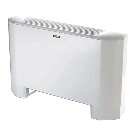
Riello HYDROLINE RK N Series Parts list manual

RK N
UNIDADES TERMINAIS A ÁGUA
FANCOIL CASSETTE
INSTRUÇÕES PARA INSTALAÇÃO,
USO E MANUTENÇÃO
INSTRUCTIONS FOR INSTALLATION,
USE AND MAINTENANCE
AS NOVAS ENERGIAS DE CLIMATIZAÇÃO

PT GB
2
DECLARAÇÃO DE CONFORMIDADE
A Empresa: RIELLO S.p.A.
com Sede em Ing. Pilade Riello, 7
37045 Z.A.I. S. Pietro di Legnago (VR)
DECLARA
sob sua própria responsabilidade que
•os VENTILOCONVECTORES
MARCA: RIELLO
SÉRIE: RK N
MODELO: RK 24 N - RK 40 N - RK 47 N - RK 63 N - RK 72 N - RK 96 N
estão em conformidade com:
•A Diretiva Máquinas 2006/42/EC
•A Diretiva Compatibilidade Eletromagnética 2004/108/EC
e com as Normas: EN 60335-1 : 2002 + A1 2004 + A11 2004 + A12 2006 +
A2 2006 + A13 2008 + A14 2010
EN 60335-2-40 : 2003 + A11 2004 + A12 2005 + A1 2006 +
A2 2009 ; EN 62233 : 2008
EN 55014-1: 2006 + A1 2009 ; EN 55014-2: 1997 + A1 2001 +
A2 2008
EN 61000-3-3: 1995 + A1 2000 + A2 2005
EN 61000-3-2: 2006 + A1 2009 + A2 2009
EN 61000-3-11: 2000
EN 61000-3-12: 2005
Primeiro nome: GIULIANO
Apelido: CONTICINI
Posição na Empresa: DIRETOR GERAL
Data 26 de abril de 2012 Assinatura

PT GB
3
Prezado Cliente,
Obrigado por escolher um produto RIELLO.
Com este manual desejamos oferecer-lhe as informações que
consideramos necessárias para uma instalação correcta e facilitada, sem
termos nada a adicionar às suas competências e capacidades técnicas.
Renovados agradecimentos.
RIELLO S.p.A.
Conformidade
O aparelho está em conformidade com as seguintes Normas:
•Diretiva Baixa Tensão 2006/95/CE
•Diretiva Compatibilidade Eletromagnética 2004/108/CE
Compliance
The unit complies with the following Standards:
•Low voltage directives 2006/95/CE
•Electomagnetic compatible directives 2004/108/CE
Gama
Garantia
O produto RIELLO beneficia de uma GARANTIA ESPECÍFICA (válida para
Itália, República de San Marino, Estado da Cidade do Vaticano), a partir da
data de validação pelo Serviço de Assistência Técnica RIELLO da sua zona.
Assim, pedimos-lhe que se dirija prontamente ao referido Serviço Técnico
RIELLO que, A TÍTULO GRATUITO, instalará o produto de acordo com as
condições especificadas no CERTIFICADO DE GARANTIA fornecido com
o produto, que sugerimos que leia atentamente.
Cassette código
RK 24 N 20051794
RK 40 N 20051795
RK 47 N 20051796
RK 63 N 20051797
RK 72 N 20051798
RK 96 N 20051799
Cassette Code
RK 24 N 20051794
RK 40 N 20051795
RK 47 N 20051796
RK 63 N 20051797
RK 72 N 20051798
RK 96 N 20051799
Painel de cobertura código
Acoplado a mod. 24-40-47 4012190
Acoplado a mod. 63-72-96 20051800
Grille panel Code
Combined with 24-40-47 4012190
Combined with. 63-72-96 20051800
Dear Customer,
Thank you for choosing a RIELLO appliance.
This booklet contains information necessary for the correct installation
of this appliance.
Thanks again.
RIELLO S.P.A.
Range

PT GB
4
Em algumas partes desta publicação são utilizados os
símbolos:
ATENÇÃO = para ações que exigem cautela especial e
preparação adequada
PROIBIDO = para ações que não devem absolutamente
ser executadas
ÍNDICE
Este manual Cód. Doc-0091218 - Rev. 0 - (02/15) é composto por
20 páginas.
Geral
Advertências gerais ......................................... 5
Regras fundamentais de segurança ............................. 5
Descrição ................................................ 6
Identificação...............................................6
Dados técnicos ............................................ 7
Dimensões ...............................................8
Esquemas eléctricos ........................................ 9
INSTALADOR
INSTALAÇÃO ..............................................10
Ligações hidráulicas .........................................12
Ligações elétricas...........................................13
Ar exterior de renovação e descarga de ar tratado em local adjacente ....14
Montagem do painel de cobertura...............................16
Instalação do kit de comutação automática ........................17
Enchimento e esvaziamento da instalação.........................17
serviço técnico de assistência
Preparação na primeira colocação em serviço ......................17
Primeira colocação em serviço .................................17
Desligar por longos períodos................................... 18
Manutenção...............................................18
Limpeza do filtro de rede......................................18
General
General notices ............................................5
Fundamental safety rules .....................................5
Description................................................6
Identifcation ...............................................6
Technical Data.......................................................................................... 7
Dimensions ...............................................8
Electrical diagrams ................................................................................... 9
Installer
Installation ................................................12
Hydraulic connections........................................14
Electrical connections ........................................15
Fresh air renewal and conditioned air supply to an adjacent room . . . 16
Installation of grille/frame assembly ..............................18
Installation of automatic changeover kit ...........................19
Loading and unloading plant ...................................19
Technical service
Preparing the frst start-up .....................................19
First start-up...............................................19
Shutting down for long periods 20
Maintenance 20
Clean the air flter 20
The following symbols are used in this publication:
WARNING = actions requiring special care and appropriate training.
DO NOT = actions that MUST ON NO ACCOUNT be carried out.
This booklet cod. Doc-0091218 - Rev. 0 - (02/15) consists of 20
pages.
Index

PT GB
5
Geral
Advertências Gerais
Após a remoção da embalagem, certifique-se de que o conteúdo
está íntegro e completo. Em caso de necessidade, dirija-se à Agência
RIELLO que vendeu o aparelho.
A instalação dos aparelhos RIELLO deve ser realizada por uma empresa
qualificada nos termos do D.M. 37/2008 que, no final do trabalho,
emita ao proprietário a declaração de conformidade da instalação
efetuada de acordo com as boas práticas, isto é, em conformidade
com as normas em vigor e com as instruções fornecidas pela RIELLO
no manual de instruções do aparelho.
Estes aparelhos deverão respeitar a destinação de uso para eles pre-
vista compativelmente com as suas características de desempenho.
Está excluída qualquer responsabilidade contratual e extracontratual
da RIELLO por danos causados a pessoas, animais ou bens, por
erros de instalação, regulação, manutenção e por usos indevidos.
Em caso de funcionamento anómalo ou de fugas de líquidos, coloque
o interruptor geral da instalação em “desligado” e feche as torneiras
de intercepção. Contacte, o mais rapidamente possível, o Serviço
de Assistência Técnica RIELLO. Não intervenha pessoalmente no
aparelho.
Uma temperatura demasiado baixa é prejudicial para a saúde e
constitui um desperdício inútil de energia. Evite o contacto direto com
o fluxo de ar durante um período prolongado.
Evite que o local permaneça fechado durante muito tempo. Periodi-
camente, abra as janelas para garantir uma ventilação adequada.
Esta publicação deve ser conservada com cuidado por ser parte
integrante do aparelho e deverá acompanhá-lo SEMPRE, mesmo em
caso de transferência para outro proprietário, utilizador ou instalação.
Em caso de danos ou extravio, solicite outro exemplar ao Serviço de
Assistência Técnica Riello local.
As intervenções de reparação ou de manutenção devem ser
efetuadas pelo Serviço de Assistência Técnica RIELLO ou por pessoal
qualificado, tal como previsto no presente manual. Não modique, nem
adultere o aparelho, pois, pode criar situações de perigo e o fabricante
do aparelho não será responsável pelos eventuais danos provocados.
General
General notices
Check the integrity and completeness of the supplied equipment as
soon as you take it out of its packaging. If necessary, consult the
Agency that sold you the equipment.
All RIELLO equipment shall be installed by skilled operators, who shall
issue a declaration of conformity for the state-of-the-art installation, that
is to say, an installation carried out pursuant to the current Legislation
and the instructions in this booklet.
These units must comply with their intended use, pursuant to
their performance characteristics.
Any contractual and tortious liability of RIELLO’s for damages to
property or people or animals because of installation, calibration
and maintenance mistakes or erroneous usage of the equipment is
excluded.
In case of abnormal operation, or leaks of liquids, position the main
switch of the system in the “of” position and close the stop taps. Call
RIELLO’s Technical Service or other professionally qualifed personnel
immediately. Do not try to repair the unit.
Too low temperatures are hazardous for the health and constitute
a useless waste of power. Avoid any prolonged direct contact with
the air fow.
The room must not remain closed for long periods of time. Open the
windows at regular intervals to ensure the correct circulation of air.
This booklet must be kept carefully as it is an integral part of the
equipment and must ALWAYS be present, including in case of sale of
the equipment to another owner or user, or of transfer to another
system. Should the manual get damaged or lost, please ask for a
duplicate manual from the RIELLO’s Technical Service.
Repairs or maintenance actions must be carried out by RIELLO’s
Technical Service staf or other skilled staf, pursuant to the provisions
of this publication. Do not modify or tamper with this equipment, as
doing so might cause dangerous situation, for which the manufacturer
waives all liability.
Regras fundamentais de segurança
O uso do aparelho é proibido por crianças e pessoas com deficiên-
cia quando não acompanhadas.
É proibido tocar no aparelho se estiver descalço ou com partes do
corpo molhadas.
É proibida qualquer intervenção técnica ou de limpeza antes de
desligar o aparelho da rede de alimentação elétrica, colocando o
interruptor geral da instalação em “desligado”.
É proibido modificar os dispositivos de segurança ou de regulação
sem a autorização e as indicações do fabricante do aparelho.
É proibido puxar, desligar, torcer os cabos eléctricos ligados ao
aparelho mesmo se este estiver desligado da rede de alimentação
eléctrica.
É proibido borrifar ou deitar água diretamente no aparelho.
É proibido introduzir objetos pontiagudos através das grelhas de
admissão e descarga de ar.
É proibido descartar, abandonar ou deixar ao alcance de crianças o
material da embalagem, por ser uma potencial fonte de perigo.
Fundamental safety rules
Do not allow children or unassisted disabled people to use the unit.
Do not touch the unit while barefoot and/or partially wet.
Do not open the access covers and carry out technical or cleaning
activities before disconnecting the unit from the power grid by
positioning the system’s main switch in the “of” position.
It is forbidden to modify the safety or regulation devices without
the authorisation and directions of the manufacturer.
Do not pull, detach or twist the electrical wires coming out of the unit,
even when the unit is disconnected from the power grid.
Do not spray or throw water directly on the unit.
It is strictly forbidden to touch any moving parts, interfere with them
or introduce pointed objects through the grids.
Do not dispose of, abandon or leave the potentially hazardous
packaging materials within the reach of children.

PT GB
6
Made in Italy
7
3
5
4
1
2
6
1Ligações hidráulicas
2Quadro elétrico
3Estrutura de suporte
4Descarga de ar em local adjacente
5Painel de cobertura
6Tomada ar exterior
7Descarga de condensados
1Water connection
2Electrical box
3Main structure
4Conditioned air supply to an adjacent room
5Grill panel
6Fresh air intake
7Drine pain
Descrição
RK N
Os ventiloconvectores RIELLO são utilizados para o aquecimento e/ou
arrefecimento de ambientes domésticos.
Estão disponíveis na versão:
•RK N para instalação em teto falso de cassette e para instalações de
2 tubos.
Unidade
•Estrutura de aço galvanizado e isolado termicamente
•Painel de cobertura com grelha de retorno de ar em ABS e defletores
de descarga de ar com regulação manual
•Ventoinha de arrefecimento: ventilador centrífugo com motor de venti-
lação multivelocidades
•Bateria de permuta composta por tubos de cobre e alhetas em
alumínio turbulentas
•Sistemas de filtragem de filtros de acrílico regeneráveis ondulados
COMANDO
•O controlo e a regulação são efetuados com os comandos disponí-
veis como acessórios para montagem na parede.
Identificação
Placa de dados técnicos
A placa de dados técnicos inclui os dados técnicos e de desempenho
do aparelho. Em caso de extravio, solicite uma segunda via ao
Serviço de Assistência Técnica RIELLO.
A adulteração, a remoção, a falta das placas de dados técnicos
ou qualquer outra coisa que não permita a identificação segura do
produto, torna difícil qualquer operação de instalação e manutenção.
Description
RK N
The fan RIELLO are used for heating and/or conditioning of environmen-
ts for civil use.
They are available in:
•RK N for ceiling installation 2-pipe systems.
UNIT
•Structure in galvanized steel and insulated
•Cover panel with ABS air intake grille and air fow bafes and defectors
air fow manually adjustable
•Fan unit: centrifugal fan motor with multi-speed fan
•Exchange coil consists of copper tubes corrugated in the aluminum
fns
•Acrylic washable corrugated flter systems, flter
CONTROL
•The control and regulation are carried out with the commands availab-
le as accessories for wall mounting.
Identifcation
Technical Tag
The technical tag shows all technical and performance data of the
unit. Should the tag get lost, please ask for a duplicate tag from the
RIELLO’s Technical Service.
Any tampering with, the removal or the lack of the Technical Tag or of
any other element whose absence prevents certain identifcation of
the product makes it more difcult to install and maintain the product.

PT GB
7
Dados técnicos
Modelo / Models 24 40 47 63 72 96
Ventiladores / Fan
Tipo de bateria / Coil type
2 tubi / 2 pipes 2 tubi / 2 pipes 2 tubi / 2 pipes 2 tubi / 2 pipes 2 tubi / 2 pipes 2 tubi / 2 pipes
Velocidade do ventilador/ Fan speed
V123123123123123123
Caudal ar / Air fow
l/s 183 125 100 204 140 89 249 173 134 272 199 147 321 229 139 443 299 166
m3/h 660 450 360 735 505 320 900 625 485 980 720 530 1160 825 500 1600 1080 600
Arrefecimento / Cooling mode
Rendimento nominal total /
Total capacity
kW
2.40 1.80 1.55 4.00 2.90 1.90 4.70 3.50 2.85 6.30 4.50 3.40 7.20 5.50 3.70 9.60 6.60 4.05
Rendimento nominal sensível /
Sensible capacity
kW
2.01 1.49 1.31 3.10 2.20 1.41 3.70 2.70 2.10 4.80 3.60 2.70 5.50 4.10 2.70 7.35 4.85 3.0
Caudal da água / Water fow rate l/s 0.11 0.09 0.07 0.19 0.14 0.09 0.22 0.17 0.14 0.30 0.22 0.16 0.34 0.26 0.18 0.46 0.32 0.19
l/h
413 310 267 688 499 327 808 602 490 1084 774 585 1238 946 636 1651 1135 697
Perda de carga / Water pressure drop,
cooling
kPa 11.1 6.5 4.9 11.0 6.2 2.9 14.7 8.6 6.0 23.3 13.6 8.7 11.6 7.0 3.4 19.8 9.9 4.0
Aquecimento / Heating mode
Rendimento nominal / Heating capacity
kW 3.20 2.50 2.20 5.00 4.00 2.50 6.20 4.60 3.70 8.11 6.00 4.50 10.00 7.40 4.60 13.00 9.30 5.20
Perda de carga / Water pressure drop,
heating
kPa 10.9 5.6 4.0 11.1 5.2 1.9 16.2 8.1 5.0 18.1 10.1 6.2 10.5 6.6 3.3 17.3 9.1 3.9
Nível sonoro / Sound levels
Nível de potência sonora / Sound
pressure level
dB(A) 47 37 32 52 44 32 57 48 42 47 40 34 53 46 37 61 52 40
Nível de pressão sonora / Sound
pressure level*
dB(A) 38 28 23 43 35 23 48 39 33 38 31 25 44 37 28 52 43 31
Fator NR / NR value*
33 23 18 38 30 18 43 34 28 33 26 20 39 32 23 47 38 26
Dados elétricos / Electrical data
Potência absorvida / Power input
W23 10 733 14 757 23 13 25 12 746 23 9115 40 11
Corrente absorvida / Current input
A0.19 0.10 0.08 0.27 0.13 0.08 0.46 0.20 0.12 0.23 0.12 0.08 0.40 0.22 0.10 0.89 0.35 0.12
Gerais / Generals
Conteúdo de água / Water content
l0.55 1.1 1.1 1.6 2.4 2.4
Diâmetro das ligações hidráulicas /
Connection diameter
in 3/4” gas 3/4” gas 3/4” gas 1” gas 1” gas 1” gas
Tubo de descarga dos condensados
diâmetro externo / Drain pipe
connection outside diameter
mm 16 16 16 16 16 16
Peso líquido da unidade / Unit net weight
kg 15 16.5 16.5 37 39.6 39.6
Peso do painel de cobertura / Grille
weight
kg 2.5 2.5 2.5 555
Cooling mode: entering air temperature 27°C db/19°C wb, entering/
leaving water temperature 7/12°C, high fan speed.
Heating mode: entering air temperature 20°C, entering water temperatu-
re 50°C, high fan speed, water fow rate as cooling mode.
* Fan speeds: 1 = high, 2 = medium, 3 = low
** Sound pressure level and NR values are based on a hypothetical
sound attenuation for the room of -9 dB(A).
For proper use, the fan must operate only within the temperatures
specifed in the table. If the unit is operated outside the above limits
may cause malfunction or loss of water.
If the room temperature can go down to 0°C, it is advisable to empty
the water circuit to avoid damage caused by ice.
Condições de referência
Arrefecimento: Entrada de ar 27 °C bs/19 °C bu, temperatura da água
entrada/saída 12/7 °C, velocidade do ventilador alta.
Aquecimento: Entrada de ar 20 °C, entrada de água 50 °C, velocidade
do ventilador alta, caudal de água no arrefecimento.
* Velocidade do ventilador: 1 = alta, 2 = média, 3 = baixa
** Os níveis sonoros e o fator NR baseiam-se numa atenuação
hipotética do local de -9 dB(A)
Terms of reference
Water side maximum pressure : 1.400 kPa
Pressão máxima do lado da água: 1400 kPa
Para uma utilização correta, o ventiloconvector deve funcionar apenas
nas temperaturas indicadas na tabela. Se a unidade for operada fora
dos limites acima indicados, podem ocorrer falhas ou fugas de água.
Se previr que a Temperatura ambiente possa descer abaixo de 0°C,
recomenda-se o esvaziamento da instalação da água para evitar
possíveis ruturas devido ao congelamento.
Technical data
Modelo / Models 24 40 47 63 72 96
Consumos elétricos / Power input
Fusível (tipo gF) / Fuse (tipo gF) A 1 1 1 1 1 1
Arrefecimento / Cooling W 70 66 106 66 97 197
Arrefecimento / Cooling A 0,33 0,29 0,46 0,32 0,52 0,91
aquecimento / Heating W 61 57 97 57 88 188
aquecimento / Heating A 0,28 0,25 0,42 0,27 0,48 0,86
ALIMENTAÇÃO / Power supply
V ~ Hz 230 ~ 50 230 ~ 50 230 ~ 50 230 ~ 50 230 ~ 50 230 ~ 50
Limiti di funzionamento Working limits
Modo de funcionamento / Function mode
Arrefecimento/Aquecimento
Cooling/Heating °C
temperatura aria / air temperature temperatura acqua / water temperature
min max min max
5 32 4 80
Tensão de alimentação / Power supply V min max
207 253

PT GB
8
Dimensões
6 0
24 - 40 - 47
63 - 72 - 96
Dimensions
Modelo / Models 24 40 47 63 72 96
Dimensões / Dimensions
Largura mm 720 720 720 960 960 960
Profundidade mm 720 720 720 960 960 960
Altura mm 298 298 298 298 298 298

PT GB
9
Esquemas elétricos
-Cablagem da empresa fabricante
---- Cablagem do instalador
FS Micro flutuador de segurança
IFM Motor ventil. Unidade interna
PS Bomba descarga
FC Condensador do motor ventil.
WV Eletroválvula
TB Régua de terminais
EC Contacto externo
*Opcional
CS Comutador mudança sazonal
FPorta-fusíveis
ACastanho
CPreto
RVermelho
GCinzento
Y/G Amarelo Verde
BAzul
WBranco
YAmarelo
OLaranja
-Factory wiring
---- Wiring by others
FS Safety micro foat
IFM Fan motor internal unit
PS Drain pump
FC Fan capacitor
WV Valve
TB Terminal block
EC External contact
*Optional
CS Change over switch
FFuse holder
ABrown
CBlack
RRed
GGrey
Y/G Yellow green
BBlue
WWhite
YYellow
OOrange
Electrical diagram

PT GB
10
Instalador
Instalação
Escolha do local de instalação
Evite:
• Locais sujeitos à luz solar direta.
• Zonas próximas de fontes de calor.
• Locais húmidos e posições em que a unidade possa entrar em con-
tacto com a água.
• Locais onde testantes ou móveis podem obstruir a circulação do ar.
Recomenda-se:
• Considerar uma área livre de obstruções que possam comprometer a
regular descarga e retorno de ar.
• Considerar uma área onde as operações de instalação sejam facilita-
das.
• Considerar uma posição que respeite os espaços mínimos de manu-
tenção aconselhados.
• Considerar uma posição que permita uma boa distribuição do ar no
ambiente.
• Instalar a unidade de modo que o condensado possa ser facilmente
drenado para uma descarga adequada.
Avisos preliminares
Instale a unidade numa posição, se possível, central no local, a dire-
ção do fluxo de ar pode ser regulada através dos defletores.
Durante o funcionamento no arrefecimento, a posição ideal das
alhetas defletoras é a que permite uma saída do ar adjacente ao teto
pelo efeito Coanda. No aquecimento, por outro lado, sua posição per-
mite direcionar o ar para o pavimento para evitar a estratificação de ar
quente na parte superior do local.
Para permitir uma instalação e manutenção rápida e fácil, verifique se,
na posição escolhida, é possível remover os painéis da do teto falso
ou, no caso de tetos falsos de alvenaria, o acesso à unidade está, de
qualquer forma, assegurado.
Antes da instalação
Transporte a unidade embalada o mais próximo possível do local de
instalação.
IMPORTANTE: Não movimente a unidade através do tubo de descar-
ga de condensados ou das ligações. Segure-a nos quatro cantos.
A instalação da unidade será mais fácil se utilizar um elevador.
No caso de tetos falsos em placas de gesso, a sede de alojamento
da unidade deve possuir dimensões não superiores a 660x660 mm
(para modelos 24-40-47) e 900x900 (para modelos 63-72-96).
No caso de ambientes com humidade elevada, isole os suportes de
suspensão com os respetivos isoladores autoadesivos fornecidos.
1Aquecimento: alheta na pos. de saída de ar
2Arrefecimento: alheta na pos. de saída de ar
3Configurações saída de ar. Para fechar os bocais, utilize os kits específicos
Installator
Installation
Choosing the installation site
Positions to avoid:
• Exposure to direct sunlight.
• Areas close to heat sources.
• On damp walls or in positions that may be exposed to water hazard.
• Where curtains or furniture may obstruct free air circulation. Recom-
mendations:
• Choose an area free from obstructions which may cause uneven air
distribution and/or return.
• Consider using an area where installation is easy.
• Choose a position that allows for the clearances required.
• Look for a position in the room which ensures the best possible air
distribution.
• Install unit in a position where condensate can easily be piped to an
appropriate drain.
Preliminary instructions
Install the unit as centrally as possible in the room, the air fow direc-
tion can be controlled by manually regulating the louvres position.
During cooling mode operation the best position for the defecting
louvres is one which allows air difusion close to the ceiling (Coanda
efect). In heating mode, the louvres should be positioned so that the
air is directed towards the foor, in order to prevent layers of hot air
forming in the upper part of the room.
In order to allow easy and rapid installation and maintenance, make
sure that in the selected position it is possible to remove the ceiling
panels or, if the ceiling is constructed of masonry, that access to the
unit is guaranteed.
Before the installation
It is advisable to place the unit as close as possible to the installation
site before removing it from the packaging.
Do not lift the unit by the condensate drain discharge pipe; hold it by
its four corners only.
Unit installation will be facilitated using a stacker.
If plaster board ceiling panels are installed the maximum dimensions
of the unit housing must not exceed 660 x 660 mm (mod. 24-40-47)
and 900 x 900 mm (mod. 63-72-96).
In rooms with high humidity, brackets should be insulated by self
adhesive insulation supplied.
1Heating: louvre position for correct air fow
2Cooling: louvre position for correct air fow
3Air outlet layout. To close the air outlets use the special kit.

PT GB
11
Instalação
- Marque a posição de cada suporte, das tubagens de ligação e des-
carga de condensados, cabos elétricos de alimentação e comandos.
O gabarito de cartão fornecido pode ser útil nesta operação.
Dependendo do tipo de teto, os tirantes podem ser instalados tal como
indicado na figura.
- Após instalar os quatro tirantes, enrosque, sem apertar, as porcas,
inserindo as anilhas tal como indicado na figura.
- Coloque previamente as tubagens de ligação tal como indicado no
parágrafo “Ligações hidráulicas” e para facilitar e agilizar a instalação,
remova o perfil em “T”.
- Levante a unidade (sem a moldura) cuidadosamente, segurando-a
nos quatro suportes de suspensão ( ou nos quatro cantos) e insira-a
no teto falso.
- Se não for possível remover o perfil em “T”, é necessário inclinar a
unidade (esta operação só pode ser efetuada na presença de tetos
falsos com altura superior a 300 mm).
- Nivele a unidade com um nível de bolha, regulando as porcas e con-
traporcas dos tirantes roscados, mantendo uma distância de 25-30
mm entre a caixa de chapa e a superfície inferior do teto falso.
- Reinstale o perfil em “T” removido anteriormente e alinhe a unidade com
os próprios perfis, apertando as porcas e as contraporcas. Por último,
depois de efetuar a ligação do tubo de descarga de condensados e das
tubagens da água, verifique se a unidade permanece nivelada.
- Mark the position of the hangers, connection lines and condensate
drain pipe, power supply cables and remote control cable.
The cardboard template (supplied with the kit) may be of assistance for
this operation.
Depending on the type of ceiling the hangers can be fxed as shown in
the drawing.
- Once the threaded hangers have been positioned, do not tighten the
nuts, and insert the washers as shown in the drawing.
- First position the connection lines , as described in the chapter “Water
connections”. Remove the “T” bar in order to facilitate installation
operations.
- Carefully lift the unit (without the frame) using the four suspension
brackets (or the four corners), inserting it into the false ceiling.
- If the “T” bar cannot be removed the unit may need to be tilted (this
operation may only be carried out with false ceilings with a minimum
height of 300 mm).
- Align and level the unit by adjusting the nuts and locknuts on the
threaded hangers, maintaining a distance of 25 -30 mm between the
sheet metal body and the underside of the false ceiling.
- Reposition the “T” bar and align the unit in relation to the bar by tightening
the nuts and locknuts. After the condensate drain pipe and the water
ducts have been connected check, check to make sure that the unit is
level.
mm
1Porcas
2Estrutura de madeira
3Tirante
4Anilhas
5Porca
6Anilhas
7Tirante
8Anilhas
9Porca
10 Porca
11 Perfil em “T” (para remover)
12 Suportes de suspensão
13 Teto falso
14 Nível de bolha
18 Caixa elétrica
1Nut
2Wooden frame
3Threaded hangers
4Washers
5Nut
6Washers
7Threaded hangers
8Washers
9Nut
10 Nut
11 T” bar (to be removed)
12 Suspension brackets
13 False ceiling
14 Spirit level
18 Electrical box
Installation

PT GB
12
On the unit startup, check if water fows correctly from the pump or che-
ck the pipe slope and make sure the pipes are not obstructed.
- To make water connections to the heat exchanger or the valves use
threaded joints and suitable materials that can ensure perfect tightness.
The unit is provided with inlet and outlet female connections.
An air bleed valve is also provided, which can be adjusted using a 8 mm
wrench..
To drain the unit completely, refer to “SYSTEM DRAINAGE” in the
Maintenance section.
Checking
Modelo / Models 24 40 47 63 72 96
Ligações hidráulicas / Water connection
Dimensões das ligações / Connections dimension “ 3/4 3/4 3/4 1 1 1
24 - 40 - 47 63 - 72 - 96
• To ensure correct condensate water fow, the drain pipe should have a
gradient of 2% without obstructions. Furthermore an odour trap of at
least 50 mm depth should be made to prevent unpleasant odours from
reaching the room.
• Condensate may be discharged at a maximum height of 200 mm
above the unit, as long as the ascending tube is vertical and aligned
with the drainage fange.
• If it is necessary to discharge the condensate from a level above 200
mm, install an auxiliary water discharge pump and foat valve. A foat
valve is recommended to stop the fow switch if there is a fault at the
auxiliary pump.
• The condensate pipe must be insulated with a condensation-proof
material such as polyurethane, propylene or neoprene of 5 to 10 mm
thickness.
• If more than one unit is installed in the room, the drain system can be
made as shown in the drawing fgure.
50
2%
4
1Cold circuit water inlet
2Cold circuit water outlet
3Air purge valve
4Multiple connection for units installed in a single room
Water connectionsLigações hidráulicas
- Efetue as ligações hidráulicas ao permutador ou às válvulas utilizando junções
roscadas ou material adequado para assegurar uma estanquidade perfeita.
A unidade está equipada com ligações fêmea na entrada e na saída.
A unida possui também uma válvula de desgasificação de ar manobrável com
chave de 8 mm.
Para a completa drenagem da unidade, consulte o parágrafo “ESVAZIAMEN-
TO DA INSTALAÇÃO” na secção manutenção.
Condensate drain pipe
Tubagem de descarga de condensados
• Para uma drenagem regular dos condensados, é necessário que o
tubo de descarga tenha uma inclinação descendente de 2% sem
estrangulamentos. Assegure também um sifão de inspeção com, pelo
menos, 50 mm de profundidade para evitar odores desagradáveis no
meio ambiente.
• É permitido descarregar a água a um nível superior à unidade de 200
mm (máximo), desde que a parte do tubo ascendente seja vertical e
esteja posicionado na flange de descarga.
• Para descarregar a água a um nível superior ao permitido 200 mm,
instale uma bomba auxiliar de descarga de condensados com tabuleiro
de recolha e regulador de nível. Recomendam-se modelos com flutua-
dor de segurança para parar a unidade em caso de falha da bomba
auxiliar.
• É necessário revestir as tubagens com material anticondensação,
como poliuretano, polipropileno, neoprene ou espuma de 5-10 mm de
espessura.
• Para várias unidades instaladas numa sala, a tubagem de recolha de
condensados deve ser realizada tal como mostrado na figura.
Verificação
No arranque da unidade, verifique se a bomba dispensa água normalmente.
Caso contrário, verifique a inclinação das tubagens e eventuais obstruções.
1Entrada de água no circuito frio
2Saída de água do circuito frio
3Válvula de desgasificação de ar
3Ligação múltipla num único local

PT GB
13
Ligações elétricas
• A unidade deve ser instalada em conformidade com as regras da instala-
ção nacionais.
• Todos os cabos de ligação à unidade, incluindo acessórios, devem ser do
tipo H05 VV-F, com isolamento de PVC de acordo com a EN 6033-2-40.
• Desligue a alimentação elétrica de todos os circuitos antes de aceder às
partes sob tensão.
• Efetue a ligação à terra antes das ligações elétricas.
• De acordo com as regras de instalação, os dispositivos de desconexão
da rede de alimentação devem prever uma abertura dos contactos (4
mm) que permita a desconexão total nas condições da categoria III de
sobretensão.
- Ligue a fonte de alimentação L (linha), N (neutro) e terra conforme indica-
do no esquema elétrico, respeitando as polaridades indicadas na parte
inferior das caixas elétricas.
Todas as unidades estão equipadas com um fusível para proteger a
máquina e outro para proteger o comando (tipo gF 1A).
Em caso de substituição do fusível de proteção da máquina, consulte a
tabela.
Quadros elétricos: o quadro elétrico está localizado no lado externo da
unidade. Retire a tampa do quadro elétrico removendo os parafusos o(s)
parafuso(s) de fecho. Dentro dos quadros estão presentes as réguas de
terminais às quais devem as ligações devem ser efetuadas de acordo com
os esquemas elétricos.
IMPORTANTE:
• Para a alimentação da unidade, recomenda-se a utilização de cabos de
secção mínima, tal como indicado na tabela
• Após efetuar as ligações, bloqueie os cabos com os respetivos protetores.
• Não se esqueça de fechar o quado elétrico com a respetiva cobertura
de proteção, utilizando o(s) parafuso(s) anteriormente removidos.
Modelo / Models 24 40 47 63 72 96
Fusível / Fuse
Fusível (tipo gF) / Fuse (tipo gF) A 1 1 1 1 1 1
Tipo / Type L N Terra / Earth
Cabos / Cable
Secção do cabo de alimentação / Unit power supply cable section mm21,5 1,5 1,5
18 Caixa elétrica
19 Passacabos
20 Régua de terminais
22 Condensador
23 Fusível
24 Entrada de cabos das válvulas
25 Cabo de alimentação
26 Cabo
27 Cabos da válvula fria
28 Cabos da válvula quente (apenas 4 tubos)
18 Electrical box
19 Cable holder
20 Terminal block
22 Capacitor
23 Fusible
24 Valve cable inlet
25 Power supply cable
26 Cable
27 Cold valve cables
28 Hot valve cables (4 pipes only)
• The unit must be installed in compliance with the national standards
on plant installation.
• All cables for connection to the unit, as well as its accessories, must be
H05 VV-F with PCV insulation in compliance with EN 6033-2-40.
• Disconnect all circuits from power supply before acting on energized
components.
• Make earthing before any other electric connections.
• In compliance with the installation instructions, the contact opening of
all disconnecting devices (4 mm) must allow full disconnection under
the conditions of overvoltage class III
- Connect power supply L (line), N (neutral) and (earthing) according to
the wiring diagram and respect the polarities shown on the bottom of
the electrical boxes.
All units are equipped with a fuse for machine protection and one
for control protection (type gF 1A).
Refer to table I when replacing the fuse for unit protection.
Control box panels: The control box panel is positioned on the external
side of the unit. Remove the fxing screws and the cover of the control box
panel. The control box panels contain the terminal blocks for connections
as shown in the wiring diagrams.
IMPORTANT:
• To power the unit, use cables with minimum section as according
to table.
• After all connections are made, fasten the cable using the special tear
protections
• Close the control box panel with the protecting cover and tighten the
screw(s) which were previously removed.
Electrical connections

PT GB
14
10 Parede
11 Porta cortada
12 Grelha na parede
13 Grelha na porta
14 Tomada ar exterior
15 Distribuição de ar em local adjacente
19 Canal de descarga em local adjacente
Fresh air renewal and conditioned air supply to an
adjacent room
• Side knockouts allow connection of fresh air inlet ducts and ducts to
deliver conditioned air to an adjacent room.
• Remove the external prepunched anti-condensate insulation and take
away the knockout panels using a punch.
• The duct lengths and the increase in noise levels caused by these
ducts can be calculated in accordance with the “air supply to an
adjacent room diagrams ” (also taking into account the fow resistance
through air difusers and fresh air flters).
• Air supply to an adjacent room requires that the outlet corresponding
with the duct is closed, using the air supply outlet obstruction kit
supplied. The kit cannot be used in units equipped with electric heater.
An air inlet grille must be ftted (if possible near the foor) between the
air conditioned room (where the unit is situated) and the adjacent room
or, alternatively, the door must be undercut, as shown in the drawing.
• The duct lengths can be calculated in accordance with the “air
distribution to an adjacent room” diagram, also taking into account the
pressure drop through air difusers and fresh air flters.
• DO NOT use active carbon or electrostatic flter kits for ducts towards
adjacent rooms.
- Remove the precut sheet metal using a punch..
- With a pencil, trace a line on the polystyrene around the inside edges
of the panel that was previously removed. Cut away the polystyrene
with a knife, taking care not to damage the heat exchange coil.
Air distribution to adjacent room
10 Wall
11 Undercut door
12 Wall-”tted grille
13 Door-”tted grille
14 Fresh air intake
15 Conditioned air supply to an adjacent room
19 Supply air duct to adjacent room
Ar exterior de renovação e descarga de ar tratado
em local adjacente
• As aberturas laterais permitem a realização separada de uma conduta
de admissão de ar externo de retorno e descarga de ar num local ad-
jacente.
• Nos “diagramas de descarga de ar para o local adjacente” é possível
determinar o comprimento das condutas de descarga (tendo em conta
também as perdas de carga através dos difusores de ar de descarga,
filtros de ar exterior) e o aumento do ruído devido a estas condutas.
Descarga de ar em local adjacente
• A descarga ar para o local adjacente requer o fecho, pelo menos, do
bocal correspondente à conduta através do respetivo kit de obstrução
de bocais de descarga. O kit não pode ser utilizado em unidades com
resistência elétrica. Entre o local climatizado (em que a unidade está
instalada) e o adjacente, é necessário instalar uma grelha de retorno de
ar (se possível, perto do pavimento) ou, em alternativa, prever uma porta
cortada conforme indicado na figura.
• O comprimento das condutas pode ser calculado com base nos “diagra-
mas de descarga de ar para o local adjacente”, tendo em conta também
as quedas de pressão através dos difusores de ar de descarga e dos
filtros de ar exterior.
• NÃO utilize os kits de filtros de carbono ou eletrostáticos na presença de
canalização para um local adjacente.
- Remova a superfície de chapa pré-cortada, utilizando um punção.
- Com um lápis, marque o poliestireno interno ao longo dos perímetros
da chapa previamente cortada, após o que, com um cortador, corte o
poliestireno, prestando atenção para não danificar a bateria de permuta
térmica por detrás.

PT GB
15
• The optional supplementary fan for fresh air intake (feld supplied) has
to be connected to terminal block as per diagrams enclosed.
Fan motor operation is parallel to the thermo-electric control valve, and
the motor stops when the valve shuts of.
• For winter operation with fresh air intake, an anti-freeze thermostat set
at 2°C is recommended, with the bulb placed on the water outlet pipe,
before the supplementary fan.
• The fresh air fow must be less than 10% of the total air fow, to avoid
operating problems or eccessive noise. For higher air fow a “primary
air kit” is available which uses the prepunched hole for air ducting to an
adjacent room and a bafe so that the fresh air is introduced into the
room through a difuser.
• Install an air inlet grille with flter inspection port to prevent dust and
dirt from entering and fouling the unit heat exchanger. Filter installation
also makes the installation of a duct closing damper during shut-down
periods unnecessary.
- Remove the precut sheet metal and install the air control device by
fxing it to the unit frame.
- Use locally purchased material, suitable for operating temperatures
of 60 °C (continuous). Conduits can be of fexible polyester (with spiral
core) or corrugated aluminium, externally covered with anti- condensate
material (fbre glass of 12 +/- 25 mm thickness).
• To complete the installation, all non-insulated ducts must be covered
with anti-condensate insulation (ex. expanded neoprene, 6 mm
thickness).
If these instructions are not observed, condensate may drip.
The manufacturer will not be held responsible for any damage caused.
14 Quadro elétrico
15 Termóstato anticongelamento
16 Variador de velocidade
17 Motor do ventilador externo
18 Relé 230 V
14 Electrical box
15 Antifreeze thermostat
16 Speed controller
17 Fresh air fan motor
18 Relay 230V
Fresh air renewalAr exterior de renovação
• O eventual ventilador suplementar para admissão do ar exterior (a cargo
do instalador) deve ser ligado à régua de terminais, conforme mostrado
nos esquemas anexados. O funcionamento do ventilador é em paralelo
com a válvula eletrotérmica de regulação, parando quando a válvula é
fechada.
• Para o funcionamento no inverno com fornecimento de ar exterior, é
aconselhável instalar um termóstato anticongelamento calibrado a 2 °C,
com o bolbo colocado na tubagem de saída de água, que intercepta o
ventilador suplementar. O caudal de ar externo deve ser inferior a 10%
do caudal de ar total, para evitar problemas de funcionamento ou ruído.
• Para caudais de ar exterior superiores a 10%, está disponível um “kit
de ar primário” no qual é utilizado o pré-corte para a descarga de ar
num local adjacente e a inserção de um septo separador para que o ar
de renovação seja introduzido no local através de um lado do difusor.
• Instale no exterior uma grelha de admissão com uma estrutura porta-fil-
tros de inspeção, para evitar que a pó e as folhas sejam aspiradas, o
que poderia obstruir irremediavelmente a bateria de permuta térmica da
unidade. A instalação do filtro evita também evita a instalação de uma
comporta de fecho do canal durante períodos de inatividade.
- Remova a superfície da chapa pré-cortada e instale o controlo do ar,
fixando-a à estrutura da unidade.
- Utilize material adquirido localmente e adequado para o funcionamento
com temperaturas de 60 °C. As condutas podem ser flexíveis em
poliéster (com núcleo de aço em espiral) ou em alumínio ondulado,
revestido externamente com material anticondensação (fibra de vidro de
12 ± 25 mm).
• Após a instalação, as superfícies não isoladas das condutas devem
ser revestidas com isolante anticondensação (por exemplo, neoprene
expandido, 6 mm de espessura).
A inobservância destas instruções pode causar gotejamentos devidos
à condensação.
A empresa fabricante não assume eventuais danos daí decorrentes.

PT GB
16
Montagem do painel de cobertura
- Desembale o conjunto e certifique-se de que não está danificado.
- Instale o conjunto na unidade, engatando-o nos dois suportes de
fixação.
- Aperte os quatro parafusos de fixação.
Na figura são evidenciadas as juntas de estanquidade que evitam o by-
pass de ar “3” e a saída de ar tratado “4” para o teto falso.
- Após a montagem do conjunto, verifique se o espaço entre a moldu-
ra e o painel falso é inferior a 5 mm.
Para a fixação da moldura, utilize apenas os parafusos fornecidos.
A moldura não deve apresentar deformações causadas por uma
tração excessiva. Deve ficar centrada em relação ao teto falso e,
acima de tudo, deve garantir a estanquidade entre a admissão e a
descarga de ar.
Installation of grille/frame assembly
- Carefully unpack the assembly and check for damage sustained in
transit.
- Install the assembly onto the unit by fxing it to the two supports
- Tightening the four fxing screws.
In the drawing gasket “3” prevents return air from mixing with the supply
air and gasket “4” prevents the supply air from leaking into the ceiling
void.
- On completion, the gap between the unit frame and the false ceiling
must not be more than 5 mm.
To fx the frame use only the screws supplied with it.
Ensure that the frame is not distorted by excessive tightening, that it is
aligned with the false ceiling and above all that there is a seal between
the air inlet and outlet.
3Junta do tipo A
4Junta do tipo B
5Descarga de ar
15 Suportes de pré-engate da moldura
16 Cordão de segurança
17 Parafusos de fixação da moldura
3Gasket “A”
4Gasket “B”
5Air discharge
15 Frame pre-hooking support
16 Safety belt
17 Frame “xing screw

PT GB
17
Instalação do kit de comutação automática
Para o funcionamento do ventiloconvector com os comandos Comfort e
Comfort Plus, é necessário instalar o kit de comutação automática.
Para instalar o dispositivo :
- Coloque o kit na tubagem de entrada
O kit deve ser colocado em contacto direto com a tubagem de
modo a garantir uma deteção de temperatura.
Enchimento e esvaziamento da instalação
Enchimento
- Antes de iniciar o enchimento, posicione o interruptor geral do sistema
em “desligado”
- Certifique-se de que a torneira de descarga da instalação está fechada
- Abra a válvula de descompressão do ventiloconvector e da instalação
- Abra os dispositivos de corte da instalação
- Inicie o enchimento, abrindo lentamente a torneira de enchimento de
água da instalação no exterior do aparelho
- Quando começar a sair água da válvula de descompressão do apare-
lho, feche-a e continue a encher até ao valor de nominal previsto para
a instalação.
Verifique a estanquidade hidráulica das juntas.
E recomendável repetir esta operação após algumas horas de
funcionamento do aparelho e verificar periodicamente a pressão da
instalação.
Esvaziamento
- Antes de iniciar o enchimento, posicione o interruptor geral do siste-
ma em “desligado”
- Certifique-se de que a torneira de carga está fechada
- Abra a torneira de descarga da instalação e todas as válvulas de
descompressão dos ventiloconvectores.
Se tiver sido adicionado líquido anticongelante à instalação, não deve
ser drenado livremente porque é poluente. Deve ser recolhido e,
eventualmente, reutilizado.
Serviço técnico de assistência
Preparação na primeira colocação em serviço
Antes de o ligar e de efetuar o teste funcional do ventiloconvector, é
indispensável verificar se:
- Todas as condições de segurança são respeitadas
- O aparelho está posicionado corretamente
- As ligações elétricas, hidráulicas e de descarga de condensados
estão efetuadas corretamente
- As válvulas de bloqueio estão abertas
- O teste hidráulico do circuito e da descarga dos condensados
tenham tido resultado positivo
Primeira colocação em serviço
- Posicione o interruptor geral do sistema em “ligado”
- Oriente a descarga do ar, utilizando os defletores manuais posiciona-
dos no painel de cobertura
- Ative o ventiloconvector com o comando
- Verifique as velocidades de funcionamento do ventilador.
Para os modos de utilização do comando, consulte as respetivas
instruções.
Installation of automatic changeover kit
To operate the fan with the controls Comfort and Comfort Plus is required
to install automatic commutation.
To install the device:
- Place the kit on the inlet pipe
The kit should be positioned in direct contact of the-pipe so as
to ensure a temperature detection.
Loading and unloading plant
Loading
- Before flling, place the master switch to “OFF”
- Check that the drain system is closed
- Open the vent valve and the fan coil system
- Open the shut of valves
- Start flling by slowly opening the water faucet outside the unit
- When water begins to leak from the unit vent valves, close them and
continue flling until the expected value for the plant.
Check the tightness of the joints.
We recommend repeating this operation once the unit has been
operating for several hours and to periodically check the system
pressure.
Emptying
- Before emptying, place the master switch to “OFF”
- Make sure the faucet is closed
- Open the drain system and any air vent fan.
If the circuit contains antifreeze, it should not be downloaded freely
because of pollution. Must be collected for possible reuse.
Technical Service
Preparing the frst start-up
Before attempting to start up and functional testing of the fan coil
is essential that:
- All the safety conditions have been met
- The device is positioned correctly
- The electrical wiring, plumbing and drain hose have been properly
- The valves are open
- The test of the hydraulic circuit and a drain has been performed
successfully
First start-up
- Set the main switch to “on”
- Direct the air fow using defectors positioned on the manual cover
panel
- Turn on the fan with the command
- Check the speed of the fan.
For how to use the command-to make reference to the attached
instructions.

PT GB
18
Desligar por longos períodos
A não utilização do ventiloconvector durante um longo período de tempo
envolve a execução das seguintes operações:
- Desative o aparelho, atuando no controlo ambiente o colocando o
interruptor principal em OFF
- Coloque o interruptor geral da instalação em “desligado”
- Feche as torneiras de água.
Se a temperatura exterior descer abaixo de zero, existe o risco de
congelamento e o sistema DEVE SER ESVAZIADO ou deve ser
adicionado anticongelante (por exemplo, etilenoglicol) nas doses
recomendadas pelo fabricante do líquido.
Manutenção
A manutenção periódica é essencial para a segurança, desempenho e
durabilidade do ventiloconvector.
Antes de iniciar as operações de manutenção:
- Remova a alimentação elétrica, posicionando o interruptor geral da
instalação em “desligado”
- Feche as torneiras de água da instalação.
O plano de manutenção que o Serviço de Assistência
Técnica ou o técnico de manutenção de seguir, com periodicidade
anual, prevê as seguentes verificações:
- Limpeza do filtro de rede
- Presença de ar no circuito hidráulico
- Tensão elétrica de alimentação
- Consumo de eletricidade
- Aperto das ligações elétricas
- Estado das juntas hidráulicas
- Descarga de condensados.
Após ter efetuado as operações de manutenção necessárias, deverão
ser restabelecidas as condições iniciais.
Planifique a periodicidade das intervenções em função das caracterís-
ticas de instalação e do tipo de utilização do aparelho.
Limpeza do filtro de rede
Antes de efetuar a limpeza do filtro de rede, é necessário retirá-lo do
aparelho.
- Rode o dispositivo de fecho 90°
- Abra a grelha de admissão
- Desengate o filtro dos respetivos suportes
- Extraia o filtro.
Após a remoção do filtro:
- Remova o pó com um aspirador.
Se houver muito pó, lave-a com água morna (máx. 40 °C) e um
detergente neutro, enxágue bem e seque à sombra.
Concluídas as operações de limpeza:
- Volte a colocar o filtro, procedendo de modo inverso.
A exposição ao sol ou temperatura da água de lavagem acima de 40
°C pode fazer com que os filtros encolham.
É proibido utilizar o aparelho sem o filtro de rede.
É proibida qualquer operação de limpeza antes de desligar o venti-
loconvector da rede de alimentação elétrica, colocando o interruptor
geral da instalação em “desligado”.
Shutting down for long periods
The non-use of the fan coil for a long period involves the making of the
following:
- Turn of the unit by the control room or by placing the power switch to
OFF
- Set the switch to “OFF”
- Close the water taps.
If the outside temperature can drop below freezing there is dan-
ger of frost and the plant MUST BE EMPTIED or be added to
themfreeze liquid (eg ethylene glycol) in the doses recommended
by the manufacturer of the liquid.
Maintenance
Regular maintenance is essential for safety, performance and durability
of the fan.
Before starting any maintenance:
- Disconnect the power supply by placing the switch to “OFF”
- Close the water valves of the system.
The maintenance plan that the Customer Services
Technical or maintenance must be observed once a year, includes the
following checks:
- Clean the air ilter
- Air fow in the hydraulic circuit
- Power supply voltage;
- Power consumption
- Tighten electrical connections
- State hydraulic joints
- Condensate drain.
After afettuato maintenance necessary must be restored to its original
condition.
Schedule the frequency of interventions depending on the characte-
ristics of installation and the type of use of the device.
Clean the air flter
Before cleaning the mesh flter is necessary to remove it from the device.
- Turn the closing device of 90 °
- Open the intake grille
- Remove the flter from its support
- Remove the flter.
After removal of the flter:
- Remove dust with a vacuum cleaner.
If the amount of dust is noticeable, wash it with warm water (max 40 ° C)
and a mild detergent, rinse well and dry in the shade.
Finish cleaning:
- Replace the flter proceeding in reverse order.
Exposure to the sun or the temperature of the wash water more than
40 ° C may restrict the flters.
The use of the unit without the flter mesh.
It prohibited any cleaning, before disconnecting the fan from the
mains electricity supply by putting the switch to “OFF”.


Doc-0091218 rev.0
Indicações para a correta eliminação do produto nos
termos da Diretiva Europeia 2002/96/EC
No final da sua vida útil, o produto não deve ser eliminado juntamente
com os resíduos urbanos. Pode ser enviado para os centros de recolha
seletiva adequados criados pelas administrações municipais ou para os
concessionários que prestem esse serviço. Eliminar separadamente um
eletrodoméstico permite evitar possíveis consequências
negativas para o meio ambiente e para a saúde
decorrentes da sua eliminação inadequada e permite
recuperar os materiais que o compõem, a fim de se
obter uma importante economia de energia e recursos.
Para sublinhar a obrigação de eliminar separadamente
os eletrodomésticos, o produto possui a marca do
contentor do lixo móvel barrado.
Sendo a nossa empresa orientada por uma política de melhoria contínua de toda a produção, as características estéticas e di-
mensionais, dados técnicos, equipamentos e acessórios são suscetíveis de variação.
As the manufacturer is constantly improving its products, the aesthetic or dimensional features, the technical data, the equipment and
accessories indicated could be subject to variations.
RIELLO S.p.A. - 37045 Legnago (VR)
Tel. 044 2630111 - Fax 044222378 -www.riello.it
Riello SpA - 37045 Legnago (VR)
Tel 0442630111 • Fax 044222378 • www.riello.it
Indications for the correct disposal of the product in
compliance with European Directive 2002/96/EC
At the end of its useful life the product must not be disposed of with other
urban waste. It can be taken to special differentiated collection centres set
up by local administrations, or else to vendors who provide this service. The
separate disposal of an electric appliance avoids negative consequences for
the environment and for health which could arise from an
inadequate disposal and means the component materials
can be recovered and possibly recycled with considerable
savings of energy and resources. There is a label with a
crossed waste bin on the product to underline this obli-
gation.
Riello SpA - 37045 Legnago (VR)
Tel 0442630111 • Fax 044222378 • www.riello.it
This manual suits for next models
6
Table of contents
Other Riello Heater manuals