Riello TAU Unit 35 User manual

cod. 20153087 rev. 3 12/2019
TAU Unit 35
EN USER MANUAL

2
Dear Customer,
Thank you for preferring a Rheating unit, a modern,
high-quality product that is able to guarantee your maximum
well-being for a long period of time, with high levels of relia-
bility and safety. In particular, if working together with a Tech-
nical Assistance Service R that is specically prepared and
trained to perform periodic maintenance, your unit will remain
at maximum efciency levels at minimum operating costs and if
required, replacements with original spare parts can be made.
This instruction manual contains important instructions and
precautions that must be observed to ensure the trouble-free
installation and efcient functioning of your TAU Unit boiler.
Please accept our renewed thanks for your purchase
Riello S.p.A.
CONFORMITY
TAU Unit boilers conform to the following directives:
−Regulation (EU) 2016/426
−Directive 92/42/EEC on efciency requirements
−Electromagnetic Compatibility Directive 2014/30/EU
−Ecodesign Directive 2009/125/CE for energy-related prod-
ucts
−Regulation (EU) 2017/1369 Energy labelling
−Low Voltage Directive 2014/35/EU
−Delegated Regulation (EU) N. 811/2013
−Delegated Regulation (EU) N. 813/2013.
ENGLISH
Thismanual,Code
-Rev.
comprises
pages.
At the end of its life, the product should be
not be disposed of as solid urban waste,
but rather it should be handed over to a
differentiated waste collection centre.

3
This manual, Code 20153087 - Rev. 3 (12/2019)
comprises 28 pages.
CONTENTS
The following symbols are used in this manual:
9 CAUTION! = Identies actions that require caution and
adequate preparation.
0 STOP! = Identies actions that you MUST NOT do.
Thismanual,Code
-Rev.
comprises
pages.
1 GENERAL INFORMATION ............................4
1.1 General Safety Information ......................4
1.2 Precautions..................................4
1.3 Description of the appliance .....................5
1.4 Safety and control devices.......................5
1.5 System layout ................................6
1.6 Control panel ................................7
1.7 Electronic control .............................8
1.7.1 Menu structure ...............................9
1.7.2 Parameters' list .............................. 14
2 USE................................................15
2.1 Putting into service ........................... 15
2.2 Switching the appliance on and off .............. 16
2.3 Ignition failure .............................. 16
2.4 Date and time setting ......................... 16
2.5 Adjustment of heating setpoint...................17
2.6 Adjustment of domestic setpoint ................ 18
2.7 Scheduled programme ........................ 18
2.8 Temporary or short-term shut-down ............. 21
2.9 Preparing for extended periods of disuse .......... 21
2.9.1 System lling and emptying .................... 22
2.9.2 CH frost protection ........................... 22
2.10 Cleaning ................................... 22
2.11 "Service reminder" function ....................23
2.12 Maintenance................................23
2.13 Troubleshooting .............................24
2.14 Useful information ...........................25
3 RECYCLING AND DISPOSAL ........................26

4
GENERAL INFORMATION
1 GENERAL INFORMATION
1.1 General Safety Information
9 After removing the packaging, check the condition and
completeness of the supply. If there are any problems, con-
tact the company Rthat sold the equipment.
9 This product must be installed by a legally qualied heat-
ing engineer. On completion of the installation, the install-
er must issue the owner with a declaration of conformity
conrming that the installation has been completed to the
highest standards in compliance with the instructions pro-
vided by Rin this instruction manual, and that it con-
forms to all applicable laws and standards.
9 This product must only be used for the purpose for which it
is designed and made, as specied by R. Rdeclines
all responsibility, contractual or other, for damage to prop-
erty or injury to persons or animals caused by improper in-
stallation, adjustment, maintenance or use.
9 The room where the boiler is installed must be proper-
ly ventilated to ensure a sufcient supply of air for correct
combustion.
9 In case of water leaks disconnect the equipment from the
power mains, close the water supply and promptly alert
Technical Assistance Service R or professionally qualied
personnel.
9 Regularly check that the condensate drain is free from ob-
struction.
9 Periodically check that operating pressure in the water cir-
cuit is over 1 bar but below the maximum limit specied for
the boiler. If this is not the case, contact Technical Assistance
Service R or a professionally qualied heating engineer.
9 Long periods of inactivity of the equipment imply the fol-
lowing operations to be carried out:
−Set the main switch of the equipment to “0”
−Set the main switch of the system to “OFF”
−Close the fuel valves and the water valves of the thermal
system
−Drain the central heating circuit if there is any risk of
freezing.
9 The product must be serviced at least once a year. Servicing
must be arranged in advance with the RTechnical Assis-
tance Service.
9 This manual is an integral part of the appliance and must
therefore be kept with care and must ALWAYS accompa-
ny the boiler, even when it is passed on to another own-
er or user or transferred to another installation. If it is lost
or damaged, please contact your local Technical Assistance
Service Rfor a new copy.
9 This manual must be read carefully so as to ensure the cor-
rect and safe installation, operation and maintenance of
the appliance. The Owner must be adequately informed
and trained on how to operate the appliance. Make sure
that he/she is familiar with all the information required for
safe system operation.
9 We recommend cleaning inside the exchanger once a year,
extracting jet and burner and removing any installation de-
bris by suction. This operation should be done by personnel
from the Technical Assistance Service only.
1.2 Precautions
The operation of any appliance that uses fuel, electrical power
and water demands that a number of fundamental safety pre-
cautions be respected:
0 Do not allow children or inrm persons to operate the sys-
tem unsupervised.
0 It is forbidden to use electrical devices or equipment, such
as switches, appliances, etc. if there is a smell of gas or un-
burnt products. If so:
−Ventilate the room, opening doors and windows
−Close the fuel shut-off cock
−Report the fault immediately to the R's Technical As-
sistance Service or a professionally qualied heating en-
gineer.
0 Do not touch the boiler while barefoot or wet.
0 Do not plug or block the condensate drain outlet.
0 Never pull, disconnect, or twist the electrical cables coming
from the appliance even if it is disconnected from the mains
electricity supply.
0 Do not obstruct or restrict the vents in the room where the
boiler is installed. Adequate ventilation is essential for cor-
rect combustion.
0 Do not expose the boiler to the elements. It is not designed
for use outdoors.
0 Do not switch off the appliance if the outdoor temperature
may drop to below ZERO (frost hazard).
0 Do not leave ammable containers and substances in the
room where the device is installed.
0 It is forbidden to activate the equipment without water.
0 The equipment casing must not be removed by people
without specic qualication and expertise.

5
GENERAL INFORMATION
1.3 Description of the appliance
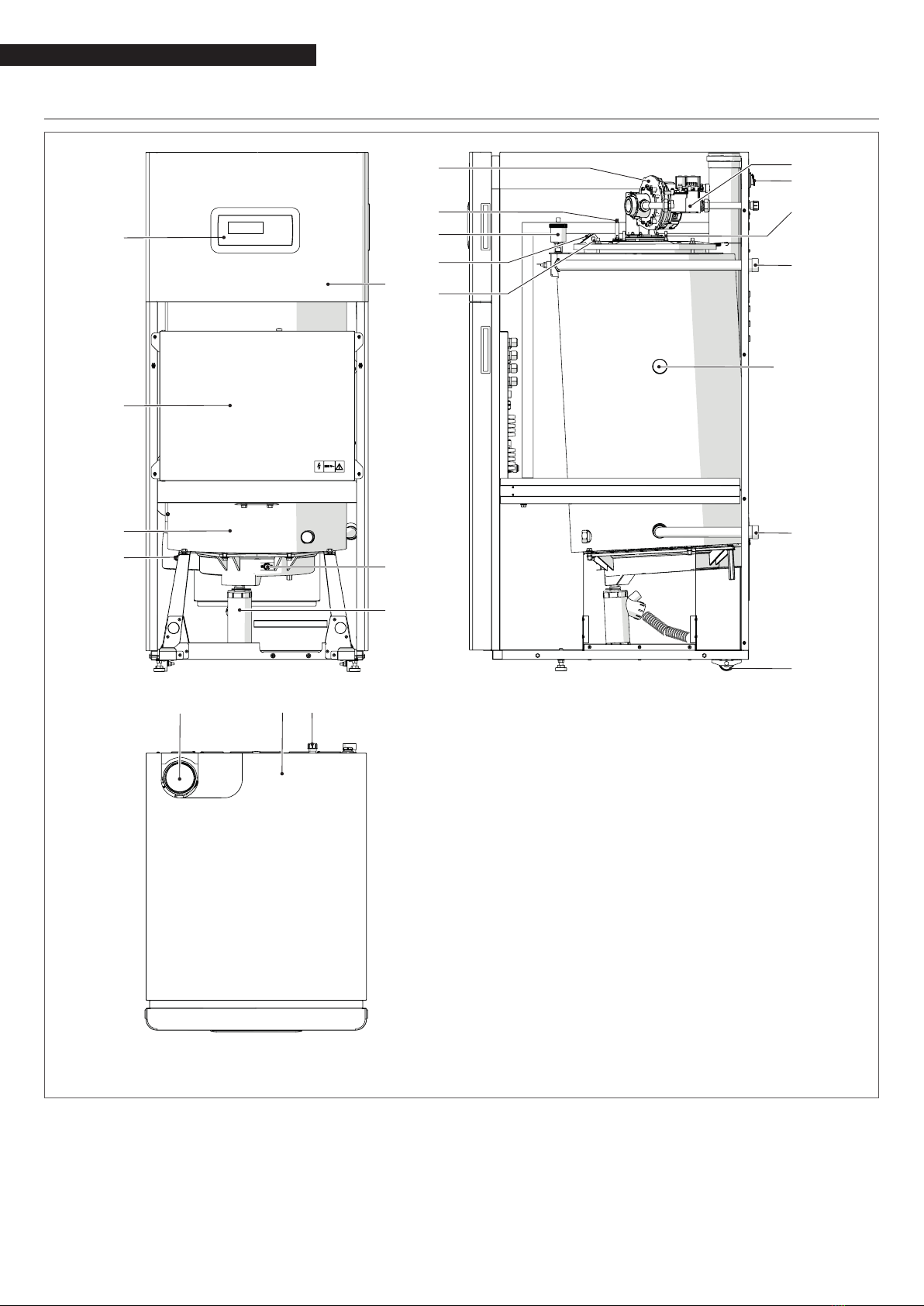
The condensing thermal unit TAU Unit is a hot water generator,
with high thermal efciency, for the heating of environments
and production of domestic hot water (DHW) coupled to an ex-
ternal heater.
The boiler body is in high alloy stainless steel and develops ver-
tically ensuring maximum duration and reliability, meeting at
the same time the most stringent national and European reg-
ulations on the emission of heavy metals in condensate drain
waters.
The double return hydraulic circuit (high or low temperature) fa-
vours temperature stratication inside the body and optimises
the performance.
The boiler body is covered in high density glass wool insulation
to reduce heat loss.
The pre-mixed microame burner with power modulation ratio
1:10 ensures low polluting emissions (NOx and CO) in compliance
with the most stringent European Regulations.
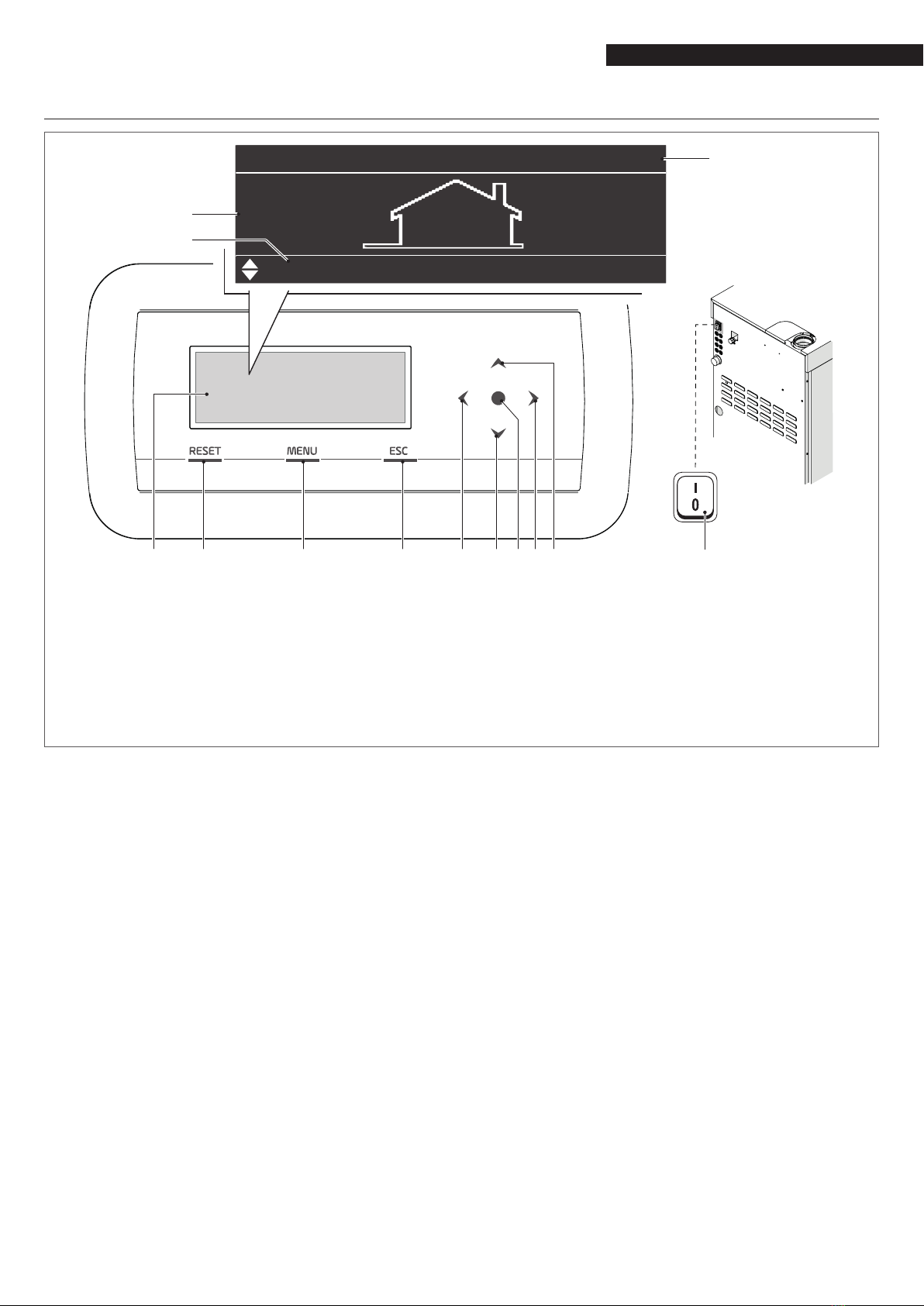
The thermoregulation with user interface and display in the
control panel TAU Unit allows managing the safety and control
devices in compliance with current regulation. By connecting
the external probe it is possible to activate the climatic control
function of the heating circuit, enhancing the seasonal energy
recovery characteristics.
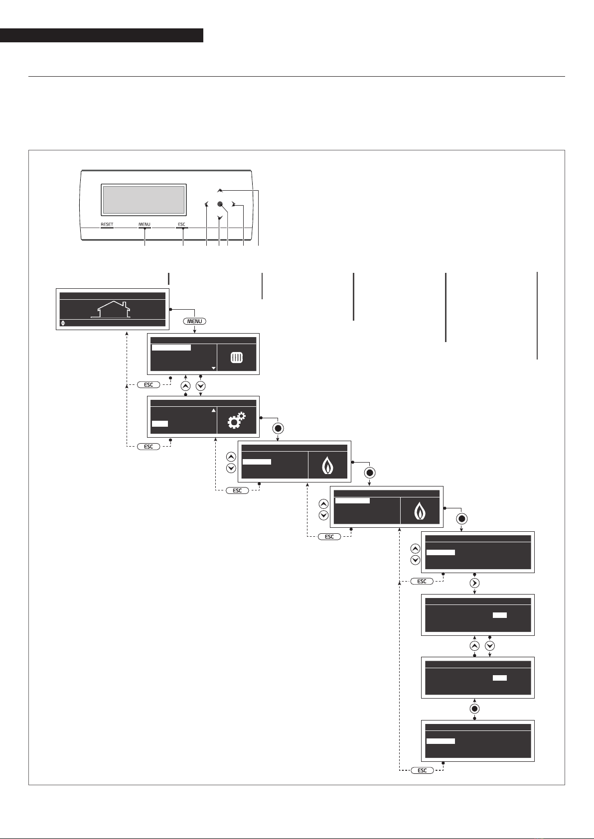
The thermoregulation adapts with exibility to the different sys-
tem needs; for example, it is possible to increase the number
of heating circuits supplied with high and low temperature and
connect the devices TAU Unit in cascade (see accessories Cata-
logue).
1.4 Safety and control devices
The thermal unit TAU Unit is equipped with the most advanced
safety and regulation systems available on the market.
Each fault is signalled through a numeric error code displayed
on the screen and stops the equipment causing the automatic
closure of the gas valve.
The following are installed on the water circuit:
−Safety thermostat: on the body of the generator, it inter-
venes to stop the appliance if the temperature exceeds
the threshold limit of 110°C.
−Delivery temperature probe: immersion probe on the
delivery line of the generator is used by the regulator
to view and check the delivery water temperature and
check the correct switching on and off of the equipment
based on the programmed setpoint. The regulator uses
the same probe to stop the generator in case of overtem-
perature, before the triggering of the safety thermostat.
−Return temperature probe: the contact probe placed
on the return line of the boiler is used by the regula-
tor to view the return water temperature with which it
calculates, together with the delivery temperature, the
temperature difference between delivery and return (∆t),
which allows regulating the modulation of the thermal
unit circulation pump in heating mode.
−Flue gas thermostat: placed in the lower part of the
exchanger, it triggers with high ue gas temperature
(>75°C).
−Flue gas probe: placed in the lower part of the exchang-
er, causes a temporary error if the temperature of the
combustion products exceeds 85°C, and a permanent
error if it exceeds 90°C.
Through specic inlets and outlets, the thermoregulation TAU
Unit allows managing the following optional safety devices out-
side the equipment:
−Pressure transducer or water minimum pressure switch:
the connection of one of the two optional devices, to be
carried out by the installer, allows the thermoregulation
to continuously view and check the pressure of the pri-
mary circuit to start or stop the equipment in case of low
pressure.
−LPG fuel shut-off solenoid valve: the thermoregulation,
via a programmable output, allows managing (based on
the designated type of fuel and system) the fuel shut-off
solenoid valve for LPG, installed outside the equipment
by the installer.
−Gas minimum pressure switch: a specic outlet is pres-
ent for the connection of the gas minimum pressure
switch (optional) to be installed outside the equipment.
The device will continuously check the correct inlet gas
pressure to start or stop the equipment in case of low
pressure.
9 The triggering of the safety devices indicates a potentially
dangerous malfunctioning of the equipment. Therefore,
immediately contact the Technical Assistance Service.
9 Safety devices must be replaced by Technical Assistance
Service, using only original parts. Refer to the spare parts
catalogue supplied with the appliance. After the repair per-
form an ignition test and check that the equipment works
correctly.
0 The appliance must not be put in service, even temporarily,
when tampered safety devices are not in operation or have
been tampered with.

6
GENERAL INFORMATION
1.5 System layout
1
5
2
3
4
7
6
20 21 22
19
10
9
11
12
8
14
13
15
16
18
17 (*)
1 Control panel
2 Electrical panel
3 Boiler body
4 Exhaust ue probe
5 Front panel
6 Flue gas limit thermostat
7 Condensate drain siphon
8 Fan
9 Ignition electrode
10 Automatic bleed valve
11 Flame inspection window
12 Combustion chamber pressure tap
13 Gas valve
14 Detection electrode
15 Main switch
16 Central heating ow
17 Ready for high-temperature system return (*)
18 Low temperature CH return
19 Wheels
20 Flue gas exhaust tting
21 Upper panel
22 Gas tting
(*) Depending on the type of system it is possible to connect the high temperature system return using the connecting pipe
of the existing low temperature system return, making sure that the connection not used is closed with the cap removed
previously.

7
GENERAL INFORMATION
1.6 Control panel
21 3 4 5 6 7 98 10
04:29
12.0
”
°C
”
“
Setp. Riscaldamento
”
48.0
”
°C
”
04:29
12.0
”
°C
”
“
CH Setpoint
”
48.0
”
°C
”
11
12
13
CONTROL INTERFACE
1255x80 point backlit display (106,4x39,0mm)
2RESET key: restores normal operations after a safety
shut-down
3MENU key: switches on the main menu
4ESC key: in menu navigation, it enables you to exit
a menu item and go back to the previous one
5 ÷ 9 Navigation keys ◄, ▼, ●, ►, ▲
10 Main switch (placed on the rear panel of the
equipment)
DISPLAY VISUALISATION
11 Outdoor temperature
12 Setpoint
13 Clockwise

8
GENERAL INFORMATION
1.7 Electronic control
The electronic control operator interface menu is a multi-level one.
Navigation between the various levels is shown in the gures below.
Level 0 displays the Home Screen (Home). Level 1 displays the Main Menu screen. The subsequent levels are activated depending on
available sub-menus.
Please note that the thermal module's operating parameters are identied with a number, whist other additional functions are
simply descriptive.
1 2 36 4 56
1 switches on the main menu
2 in menu navigation, it enables you to exit a menu item
and go back to the previous one
3 supports selecting menus or parameters or decreasing
numeric values
4 enter
5 supports selecting menus or parameters or increasing
numeric values
6 supports moving to the RH/LH area of the display
Level 1Level 0 Level 2 Level 3 Level 4
“
“
“
“
“
04:29
12.0
”°C”
“CH Setpoint”48.0”°C”
“
Menu
”
“Central Heating (CH)”
“Domestic Hot Water (DHW)”
“Information”
“Settings”
“
Menu
”
“Domestic Hot Water (DHW)”
“Information”
“Settings”
“System Test”
“
Settings
”
“General Settings”
“Boiler Settings”
“
Boiler Settings
”
“Boiler Parameters”
“
Module Cascade Settings”
“Boiler Cascade Settings”
“Service”
“
Boiler Parameters
”
“(1) CH Mode”
0°
“(3) CH Setpoint”85.0 “°C”
“(185) Calc. Setp. Offset”
0.0 “°C”
“(110) CH Min Setpoint”
20.0 “°C”
“
Boiler Parameters
”
“(1) CH Mode”
0°
“(3) CH Setpoint”
85.0 “°C”
“(185) Calc. Setp. Offset”
0.0 “°C”
“(110) CH Min Setpoint”
20.0 “°C”
“
Boiler Parameters
”
“(1) CH Mode”
0°
“(3) CH Setpoint”
86.0 “°C”
“(185) Calc. Setp. Offset”
0.0 “°C”
“(110) CH Min Setpoint”
20.0 “°C”
“
Boiler Parameters
”
“(1) CH Mode”
0°
“(3) CH Setpoint”86.0 “°C”
“(185) Calc. Setp. Offset”
0.0 “°C”
“(110) CH Min Setpoint”
20.0 “°C”

9
GENERAL INFORMATION
1.7.1 Menu structure
Home /
”
Menu
” “
Central Heating (CH)
”
“
Information
”
“
CH Setpoint
”
“
Software Versions
”
“
Outdoor reset
”
“
Boiler Status
”
“
Boiler History
”
(external probe accessory)
30,0
“
°C
”
- 90,0
“
°C
”
“
Des. Supply T.
”
“
Display
”
“
Flow Temperature
”
“
0-10 V Input
”
“
Successful Ignitions
”
“
Bas. Supply T.
”
“
Boiler
”
“
Flow 2 Temperature
”
“
Flowrate
”
“
Failed Ignitions
”
“
WW Shutdown
”
“
Device Group
”
“
Return Temperature
”
“
RT Input
”
“
Outside Temperature
”
“
State
”
“
Flame Failures
”
“
Bas. Outd. T.
”
“
DHW Temperature
”
“
Fan Speed
”
“
Flue Temp
”
“
Error
”
“
Operation Days
”
“
Des. Outd. T.
”
“
DCW Temperature
”
“
Ionisation
”
“
System Temperature
”
“
Calculated Setpoint
”
“
CH Burner Hours
”
“
DHW Burner Hours
”
“
Domestic Hot Water (DHW)
” “
DHW Setpoint
”
Level 0 Level 1 Level 2 Level 3 Level 4 Level 5 Level 6

10
GENERAL INFORMATION
"
Error Log
"
"
General Settings
"
"
Service
"
"
Error Log
"
"
Service history
"
"
Burn hours till service
"
"
Disabled
"
"
Italiano
"
"
Time Zone Correction
"
"
Time Notation
"
"
Year
"
"
Day Of Month
"
"
Day Of Week
"
"
Date:
"
"
Metric (°C, Bar)
"
"
Filter Error Type
"
"
Language
"
"
Date & Time
"
"
Unit Type
"
"
Burn hours since last service
"
"
Reset Service Reminder
"
"
Clear Service History
"
"
Blocking
"
"
Nederlands
"
"
Português
"
"
Daylight Savings Time
"
"
Date Order
"
"
Date Separation Character
"
"
Month
"
"
Seconds
"
"
Time:
"
"
Imperial (°F, PSI)
"
"
Lockout
"
"
Deutsch
"
"
Español
"
"
Français
"
"
English
"
"
Time Zone Settings
"
"
Display Settings
"
Home /
"
Menu
" "
Information
"
"
Settings
"
Level 0 Level 1 Level 2 Level 3 Level 4 Level 5 Level 6

11
GENERAL INFORMATION
“
Program Group
”
“
Program CH
”
1 - 8
“
Program Comfort Period
”
“
Comfort Setpoint
”
“
ECO Setpoint
”
“
Group Holiday
”
1 - 7
10,0
“
°C
”
- 30,0
“
°C
”
5,0
“
°C
”
- 20,0
“
°C
”
“
Select Ext. Zones in Group
”
“
Enabled
”
“
Active Day(s)
”
“
Interval 1
”
“
Interval 2
”
“
Interval 3
”
“
Enabled
”
“
Enabled
”
“
Period Disabled
”
00:00 - 23:50
00:00 - 23:50
00:00 - 23:50
“
Monday-Friday
”
“
Monday
”
,
”
Tuesday
”
,...,
”
Sunday
”
“
Zones
”
“
CH
”
1 - 16
“
Disabled
”
“
Disabled
”
“
Disabled
”
“
Saterday-Sunday
”
“
Monday-Sunday
”
Home /
”
Menu
” “
“
Clock Program
”
Level 0 Level 1 Level 2 Level 3 Level 4 Level 5 Level 6
“
General Settings
” “
Cascade mode
”“
Full
”
“
Basic
”
Settings
”

12
GENERAL INFORMATION
“Program CH” “Out of interval setpoint”“Off”
“Comfort”
“Eco”
“Anti Fr”
“Reduced”
“Off”
Home /”Menu” “Clock Program”
“Program DHW”
“Holiday Settings”
“Out of interval setpoint”“On”
1 - 7
“Off”
“Group”
“Active Day(s)”
1 - 8
“Interval 1”
“Interval 2”
“Interval 3”
“Period Disabled”
“Holiday Setpoint”
“Begin Date”
“End Date”
00:00 - 23:50
00:00 - 23:50
00:00 - 23:50
“Monday-Friday”
“Monday”,”Tuesday”,...,”Sunday”
“Saterday-Sunday”
“Monday-Sunday”
“Program Comfort Period”
“Mode”
“Off”
00-00-0000
00-00-0000
“Comfort”
“Eco”
“Anti Fr”
“Reduced”
Level 0 Level 1 Level 2 Level 3 Level 4 Level 5 Level 6

13
GENERAL INFORMATION
"Holiday Settings" "Mode"
Home /"Menu" "Clock Program"
"Season Settings""Off""Mode"
"System"
"On Temp"
"On Date"
"Holiday Setpoint"
"System Test"
"Outdoor Temp. Below"
"Off"
"Test State" "Off"
0,0 "°C"- 50,0 "°C"
"Comfort"
"Fan Speed" "Low Power"
"Eco"
"Ionisation" "High Power"
"Anti Fr"
"Reduced"
"Begin Date"
"Begin Date"
"End Date"
"End Date"
00-00-00
00-00-00
00-00-00
00-00-00
Level 0 Level 1 Level 2 Level 3 Level 4 Level 5 Level 6

14
GENERAL INFORMATION
1.7.2 Parameters' list
9 The programming lines can be hidden, according to the access level (User, Installer, Manufacturer) and to the thermal unit
conguration.
9 The parameters of the Installer and Manufacturer levels should only be changed by Technical Assistance Service R.
Parameters are listed base on the reference menu.
Reference Menu
M1 Parameters Menu
Access type
UEnd user
Menu
Par.
No.
Nr. dis-
played
Display
Description Range Default set-
ting
UM
Access
type Category
M1 3CH set-
point
It denes the desired delivery temperature
with heating mode (Par. 1 = 0).
Par. 23…Par.
24 70 °C UHeating
M1 19 Design Sup-
ply Temp.
Denes the max. set-point at the minimum
outdoor temperature for climatic regulation. 30…90 80 °C UHeating
M1 20 Design Out-
door Temp.
Denes the minimum outdoor temperature to
which the maximum set-point can be associ-
ated for climatic regulation.
-25…25 0°C UHeating
M1 48 DHW tank
set-point
Establishes the DHW storage tank set-point
Par. 35 in mode 2. 40…71 50 °C UDHW
M1 115
DHW stor-
age tank
setp.
Denes the Accumulation sanitary Setpoint in
mode 1 40…71 57 °C UDHW

15
USE
2 USE
2.1 Putting into service
9 The appliance must be maintained and adjusted at least
once a year by Technical Assistance Service or by profession-
ally qualied staff in compliance with all applicable Nation-
al and Local provisions.
9 Incorrect maintenance or adjustment may damage the ap-
pliance and cause damage to people or create a hazard.
9 The system manager is forbidden from opening and remov-
ing the appliance's casing. These activities must be carried
out only by Technical Assistance Service or by professionally
qualied personnel.
The thermal module TAU Unit Rmust be commissioned by
Technical Assistance Service R, after which step the appliance
may operate automatically.
However, the system manager may be required to restart the
appliance independently, without involving Technical Assistance
Service; for example after a long period of absence.
To do so, perform the following checks and operations:
−Check that the fuel valves and the water valves of the
thermal system are open
−While the system is still cold, check that working pressure
in the central heating circuit is over 1 bar but below the
maximum limit specied for the boiler
−Adjust the room thermostats for the high and low tem-
perature zones to the required temperature (~20°C) or,
if the systems are equipped with timer thermostats or a
time programming unit, make sure it is on and adjusted
(~20°C)
−Switch the system's master switch to the ON position and
the thermal module's master switch to (I).
The appliance will go through the switch-on stage and, after
starting, it will continue to operate until set temperatures are
achieved.
The burner will then switch off and on automatically to main-
tain the set temperature without further operator action.
In the event of ignition or operation faults, the display will show
a numeric error code that will enable the user to interpret the
possible cause as detailed in Paragraph "Error List".
9 In the event of a permanent error, to reset starting condi-
tions press the "RESET" key and wait for the thermal module
to restart.
Repeat this operation 2-3 times at the most. If the problem per-
sists after that, call R’s Technical Assistance Service.

16
USE
2.2 Switching the appliance on and off
After switching the appliance on, the display shall look as shown
in the gure below:
04:29
12.0
”°C”
“CH Setpoint”48.0”°C”
External temperature is shown on the display on the left. This
value is displayed only if the outdoor temperature sensor (ac-
cessory) is installed.
Main setpoint values are shown in the lower side of the display
while the time is shown on the top right side.
To turn the equipment off set the main switch “0/I” that is
placed on the back side to “0”.
9 Never power off the appliance before switching the master
switch to the "0" position.
9 Never switch off the appliance with the master switch if a
request is active. Always make sure that the appliance is in
stand-by before switching the main switch.
2.3 Ignition failure
If an anomaly of ignition or operation occurs, a variable mes-
sage will be indicated on the display of the command interface
based on the anomaly found.
Try to manually reset the device by holding down the key "RESET"
(1).
1
Check the paragraph "Troubleshooting" if the normal operation
of the appliance can be restored, otherwise contact the Techni-
cal Assistance Service
2.4 Date and time setting
Press the MENU key and select "Settings" with the ▲/ ▼keys
“
Menu
”
“Central Heating (CH)”
“Information”
“Settings”
“System Test”
Conrm with the ●key and select "General settings" with the
▲/ ▼keys
“
Settings
”
“General Settings”
“Boiler Settings”
Conrm with the ●key and select "Date and Time " with the ▲
/ ▼keys
“
General Settings
”
“Language”
“Unit Type”
“Date & Time”
“Cascade mode”
Press the ●key, the display will be shown as follows:
“
Date & Time
”
“Date:”“Sunday” 10/25/2015
“Time:” 03:02
“Time Zone Settings”
“Display Settings”
Press the ●key to highlight the values.
“
Date & Time
”
“Date:”
“Sunday” 10/25/2015
“Time:”03:02
“Time Zone Settings”
“Display Settings”
Values can be changed with the ▲/ ▼keys.
Conrm the value entered pressing the ●key and move to the
next value.

17
USE
“
Date & Time
”
“Date:”
“Sunday” 10/25/2015
“Time:”03:02
“Time Zone Settings”
“
Display Settings
”
To set the time, follow the same procedure.
By accessing the "Time Zone Set." menu, it is possible to set the
time zone parameter as shown in the gure below:
“
Time Zone Settings
”
“Time Zone Correction”UTC +00.00
“Daylight Savings Time” “Disabled”
To change the way in which date and time are displayed, it is
possible to change the following characteristics by accessing the
"Display Parameters" menu:
“Display Settings”
“Time Notation” “24h”
“Date Order” “DMY”
“Day Of Month” “2Digits”
“Month” “2Digits”
“
Display Settings
”
“Year” “4Digits”
“Date Separation Character” “-”
“Day Of Week” “Short Text”
“Seconds” “No”
2.5 Adjustment of heating setpoint
The set-point value can be entered directly, without entering in
the parameter list, by accessing the “CH” menu in the following
way:
Press MENU and select "Central heating" using the ▲/ ▼keys.
Press the ● key to conrm.
“
Menu
”
“Central Heating (CH)”
“Domestic Hot Water (DHW)”
“Information”
“Settings”
After the selection, use the ►key to highlight the value and use
the ▲/ ▼keys to change the selected value. Press the ●key to
conrm/save the new settings..
“
Central Heating (CH)
”
“CH Setpoint”61.5 “°C”

18
USE
2.6 Adjustment of domestic setpoint
The setpoint value can be set directly, without entering the list
of the parameters:
−Press MENU and select "Domestic Hot Water" using the ▲
/ ▼keys.
“
Menu
”
“Central Heating (CH)”
“Domestic Hot Water (DHW)”
“Information”
“Settings”
−Press the ● key to conrm.
“
Domestic Hot Water (DHW)
”
“DHW Setpoint”45.0 “°C”
−Use the ►key to highlight the value, and use the ▲/ ▼
keys to change the selected value. Press the ●key to con-
rm/save the new settings..
2.7 Scheduled programme
The Scheduled Programme is designed to program the opera-
tion of the various circuits managed by the thermal module, (CH,
DHW and additional mixed zones).
Seasonal Programme
The Seasonal Programme is use to exclude additional mixed
zones during the summer season.
It does not control any DHW parameter.
Holiday Programme
The Holiday Programme is used to exclude part of or all the cir-
cuits at a certain time of the year.
A holiday can be set both on the full system and on various
groups of circuits.
The group system enables the user to add various circuits to the
group to set a holiday period for several circuits at the same
time. (For instance, to manage a semi-detached house with a
centralised heating system when one of the two families is on
holiday and the other is not).
The set-point type can be adjusted so as to correspond to the
desired setting.
The system can control up to a total of 16 "Mixed" zones. The
programming of mixed areas is only allowed with an accessory.
At the same time as these 16 areas, it is also possible to enable
the CH zone (direct zone for central heating only).
“
Clock Program
”
“Program Group”
“Burn hours till service”
“Reset Service Reminder”
“Holiday Settings”

19
USE
The time programme includes the following parameters:
Group Programming
“
Group
”
1
“Group Holiday” “Enabled”
“Select Ext. Zones in Group”
“Select Dep. Zones in Group”
It enables the user to select a group to add zones to the selected
group. It also enables the user to enable/disable the group in
question.
Group settings are used to add zones to the groups.
The “Group programming” menu enables the use to chose
among 8 groups. Each of them can be enabled or disabled.
Within it, it is possible to select zones to be added to the group
(direct zone (CH) - mixed zones from 1 to 16)
“
Select Ext. Zones in Group
”
1
“External Zone” “CH” “Disabled”
“External Zone”1“Disabled”
“External Zone”2“Disabled”
“External Zone”3“Disabled”
N.B. The programming of mixed areas is only allowed with an
accessory.
Heating programming
“
Group
”
1
“Program Comfort Period”1
“Comfort Setpoint” 28.0 “°C”
“ECO Setpoint”20.0 “°C”
“Out of interval setpoint” “Reduced”
It supports adjusting the time programme for the CH zones with
the following parameters:
Period setting
Enables the user to select a period from 1 to 7. Period settings
enable the user to adjust the active periods for this zone.
−Active days: Selection of the day (s) on which the period
is active. Enables the user to disable the period set for
one or more days. When this parameter is set as inac-
tive, the other items on this menu are no longer used
and hidden from the view. The choice of active days is
between the following macro-groups: Sat-Sun, Mon-Fri,
Mon-Sun, or individual days: Mon, Tue, Wed,...
−Interval 1 (hidden if Active Days is disabled): This param-
eter allows the user to regulate the starting and end time
of the period. The starting time must always be before
the nishing time.
−Interval 2 (hidden if Active Days is disabled): Same as
interval 1. Interval added for the activated period.
−Interval 3 (hidden if Active Days is disabled): Same as
interval 1. Interval added for the activated period.
“Group” 1
“Program Comfort Period”71
“Comfort Setpoint” 28.0 “°C”
“ECO Setpoint”20.0 “°C”
“Out of interval setpoint” “Reduced”
“
External Zone
”
CH -
“
Period
”
1
“Active Day(s)” “Sunday”
“Interval 1”00:00 00:00
“Interval 2”00:00 00:00
“Interval 3”00:00 00:00
Comfort Set-point
Comfort temperature to be used when the zone is in a certain
period. (10 -30 °C)
ECO set-point
ECO temperature. Adjustable temperature that can be used out-
side set periods (5 – 20 °C).
Set-points outside the interval
Selection of the type of set-point to be used when a zone is not
on a set period by selecting between:
−Off
−Comfort
−Eco
−Anti-Freeze (is activated below 5°C NON-ADJUSTABLE)
−Reduced (Calculated as -10°C Comfort Set-point value)

20
USE
DHW setting
“
Group
”
1
“Program Comfort Period”1
“Out of interval setpoint” “On”
It supports adjusting the time programme for the DHW zone.
Period setting
Enables the user to select a period from 1 to 7. Period settings
enable the user to adjust the active periods for this zone.
−Active days: Selection of the day (s) on which the period
is active. Enables the user to disable the period set for
one or more days. When this parameter is set as inac-
tive, the other items on this menu are no longer used
and hidden from the view. The choice of active days is
between the following macro-groups: Sat-Sun, Mon-Fri,
Mon-Sun, or individual days: Mon, Tue, Wed,...
−Interval 1 (hidden if Active Days is disabled): This param-
eter allows the user to regulate the starting and end time
of the period. The starting time must always be before
the nishing time.
−Interval 2 (hidden if Active Days is disabled): Same as
interval 1. Interval added for the activated period.
−Interval 3 (hidden if Active Days is disabled): Same as
interval 1. Interval added for the activated period.
“Group” DHW
“Program Comfort Period”71
“Comfort Setpoint” 28.0 “°C”
“ECO Setpoint”20.0 “°C”
“Out of interval setpoint” “Reduced”
“
External Zone
”
DHW -
“
Period
”
1
“Active Day(s)” “Sunday”
“Interval 1”00:00 00:00
“Interval 2”00:00 00:00
“Interval 3”00:00 00:00
Set-points outside the interval
Selection of the type of set-point to be used when a zone is not
on a set period by selecting between:
−Off
−On
Holiday setting
“
Holiday Settings
”
“Mode” “Group”
“Group”1
Enables the user to change parameters for the Holiday Pro-
gramme.
Mode
Select the Holiday programme mode. It can be set to Off, System
or group.
Off
Disabled programme
Group
it enables the selection of the group (1 – 8).
As part of group selection, the Holiday Group is displayed with
the following parameters:
−Holiday set-point: Set-point type to be used for the se-
lected group. All zones in this group shall use this set-
point if the current date is between the start and end
date of the holiday period, but only if the group is en-
abled in the group settings menu, and can be selected
from: Off, Comfort, Eco, Anti-freeze and Reduced.
−Start date / End date (Day DD-MM-YEAR):
“Group” DHW
“Program Comfort Period”71
“Comfort Setpoint” 28.0 “°C”
“ECO Setpoint”20.0 “°C”
“Out of interval setpoint” “Reduced”
“
External Zone
”
DHW -
“
Period
”
1
“Active Day(s)” “Sunday”
“Interval 1”00:00 00:00
“Interval 2”00:00 00:00
“Interval 3”00:00 00:00
−System: It enables the user to select the holiday pro-
gramme for the entire system. In this mode, the set-
point is common to all system groups.
“
Group
”
DHW
“Program Comfort Period”71
“Comfort Setpoint” 28.0 “°C”
“ECO Setpoint”20.0 “°C”
“Out of interval setpoint” “Reduced”
“
External Zone
”
DHW -
“
Period
”
1
“Active Day(s)” “Sunday”
“Interval 1”00:00 00:00
“Interval 2”00:00 00:00
“Interval 3”00:00 00:00
−Holiday set-point (hidden if the Mode is set to “Off”):
Type of reference to be used when system mode is select-
ed. This set-point is used for all areas. Only used for the
holiday system.
Table of contents
Other Riello Heater manuals
Popular Heater manuals by other brands

Kospel
Kospel OSV.ECO Slim Assembly and operating manual

ARDES
ARDES AR4U80 Instructions for use

PoolMaster
PoolMaster 59026 Installation and instruction manual

Vortice
Vortice SCALDATUTTO Instruction booklet

HIRED-HAND
HIRED-HAND Super Saver XL Conversion instructions

winkler
winkler WOCP operating instructions