manuals.online logo
Brands
  1. Home
  2. •
  3. Brands
  4. •
  5. RINGSPANN
  6. •
  7. Industrial Equipment
  8. •
  9. RINGSPANN RDZ DTO Series User manual

RINGSPANN RDZ DTO Series User manual

10550 Anderson Place
Telephone 847 678-3581
Fax 847 678-3583
www.ringspanncorp.com
info@ringspanncorp.com
Franklin Park, IL 60131
United States
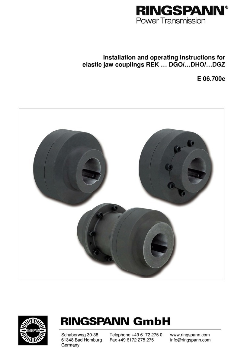
Installation and operating instructions for
torsionally stiff gear couplings RDZ … DTO/… DFO
E 06.705e
Installation and opreating instructios for tor-
sionally stiff gear couplings RDZ…DTO/…DFO
E 06.705
As of: 12.08.2020
Version: 02
Signed: SCCE
Checked: SCHW
No. of pages: 21
Page: 2
Important
Before installation and commission of the product begins, these installation and operating instructions
must be read carefully. Notes of caution, and hazard warnings, should be read and understood.
These installation and operating instructions apply on condition that the product meets the selection
criteria for its proper use. The selection and dimensioning of the product are not the subject of these
installation and operating instructions.
If these installation and operating instructions are not observed or are interpreted incorrectly, this shall
invalidate any product liability and warranty of RINGSPANN CORPORATION; the same also applies
in the case that our product is taken apart or changed.
These installation and operating instructions are to be kept in a safe place and must, in the event of
onward delivery of our product –be it individually or as part of a machine –be passed on along with
the product so that the user has access to them.
Safety information
•The installation and commissioning of our product may only be carried out by trained personnel.
•Repair work may only be performed by the manufacturer or by authorised RINGSPANN agencies.
•If there is a suspected malfunction, the product, or the machine into which it is built, must be taken
out of operation immediately and RINGSPANN CORPORATION or an authorised RINGSPANN
agency must be informed.
•The power supply must be turned off during work on electrical components.
•Rotating parts must be secured by the operator against unintentional contact.
•In the case of supplies made to a foreign country, the safety regulations applicable in that country
must be taken into consideration.
German original version!
If there should be any discrepancies between the German original and versions of these installa-
tion and operating instructions in other languages, the German version shall take precedence.
Installation and opreating instructios for tor-
sionally stiff gear couplings RDZ…DTO/…DFO
E 06.705
As of: 12.08.2020
Version: 02
Signed: SCCE
Checked: SCHW
No. of pages: 21
Page: 3
Contents
1. General information
1.1. Function
1.2. General safety instructions
1.3. Other applicable provisions, standards etc.
2. Design and function / parts list
2.1. Labelling
2.2. Dimensions
2.3. Parts list
3. Intended use
4. Warning signs / Impermissible use
5. Condition as delivered
6. Storage
7. Technical prerequisites for reliable operation
7.1. Permissible operating parameters
7.2. Permissible misalignments
7.3. Hub bore specifications
8. Assembly
8.1. General assembly instructions
8.2. Assembly description
8.3. Alignment procedure
8.3.1. Check the radial misalignment
8.3.2. Check the angular misalignment
9. Start-up and lubrication
9.1. Start-up
9.2. Lubrication
10. Operational disturbances
11. Maintenance and repair
12. Spare part stockpiling
13. Disposal
Installation and opreating instructios for tor-
sionally stiff gear couplings RDZ…DTO/…DFO
E 06.705
As of: 12.08.2020
Version: 02
Signed: SCCE
Checked: SCHW
No. of pages: 21
Page: 4
1. General information
1.1. Function
The main function of the torsionally stiff gear coupling consists of transferring the torque of
one shaft end onto another shaft. Additionally, the coupling is designed to compensate for
angular, radial and axial misalignments.
1.2. General safety instructions
Safety takes the highest priority during installation and operation
To ensure this, the following safety instructions must be observed:
- During installation and maintenance work, the drive motor must be secured against un-
intended start-up and the load side locked against turning.
- Accidental contact with the coupling during operation must be prevented with a suitable
cover or protective device.
- Do not reach into the working area of the coupling during operation.
1.3. Other applicable standards.
The design of the coupling is carried out with the help of operating factors that come from
experience (see RINGSPANN catalogue “shaft coupling”). If the operating conditions (e.g.
output, speed) should change, the original design of the coupling must be reviewed to de-
termine if it is still the proper selection.
2. Design and function / parts list
2.1. Labeling
Depending on the coupling size, the parts are labeled as follows:
Hubs:
- RINGSPANN logo
- Abbreviated designation
Installation and opreating instructios for tor-
sionally stiff gear couplings RDZ…DTO/…DFO
E 06.705
As of: 12.08.2020
Version: 02
Signed: SCCE
Checked: SCHW
No. of pages: 21
Page: 5
2.2. Dimensions
Figure 2.1: Drawing RDZ … DTO Figure 2.2: Drawing RDZ … DFO
Table 2.1: Dimensions RDZ … DTO
Size
D
inch
D1
inch
D2
inch
D3
inch
F1
inch
F2
inch
L
inch
L1
inch
M
inch
O
inch
0010
4.56
2.72
3.31
3.31
1.69
1.57
3.43
1.54
2.01
0.16
0015
6.00
3.39
4.13
4.21
1.97
1.85
3.98
1.89
2.40
0.16
0020
7.00
4.13
5.00
5.12
2.44
2.32
4.92
2.36
2.99
0.16
0025
8.38
5.16
6.10
6.18
3.03
2.91
6.14
2.83
3.62
0.20
0030
9.44
5.98
7.13
7.17
3.58
3.46
7.24
3.31
4.17
0.20
0035
11.00
7.01
8.31
8.35
4.21
4.02
8.46
3.86
5.12
0.24
0040
12.50
8.27
9.84
9.84
4.76
4.57
9.65
4.37
5.71
0.31
0045
13.63
9.25
10.79
10.87
5.31
5.16
10.79
4.84
6.50
0.31
0050
15.31
10.00
12.05
12.17
6.02
5.83
12.20
5.55
7.20
0.35
0055
16.75
10.98
13.15
13.15
6.61
6.81
13.78
6.22
7.99
0.35
0060
18.00
12.01
14.41
14.41
7.40
7.28
15.12
6.65
8.98
0.39
0070
20.75
14.02
16.73
16.73
8.70
8.58
17.80
7.72
10.47
0.51
0080
23.23
15.16
19.09
18.50
9.80
9.80
20.12
9.57
11.81
0.51
0090
26.00
16.54
21.06
20.39
10.87
10.87
22.32
10.43
12.80
0.59
0100
28.00
18.50
23.43
22.52
12.01
12.01
24.65
11.57
13.98
0.63
Table 2.2: Dimensions RDZ … DFO
Size
D
inch
D1
inch
D2
inch
F
inch
L
inch
L1
inch
M
inch
O
inch
0010
4.56
2.72
3.31
1.69
3.50
1.54
2.01
0.12
0015
6.00
3.39
4.13
1.97
4.06
1.89
2.40
0.12
0020
7.00
4.13
5.00
2.44
5.00
2.36
2.99
0.12
0025
8.38
5.16
6.10
3.03
6.26
2.83
3.62
0.20
0030
9.44
5.98
7.13
3.58
7.36
3.31
4.17
0.20
0035
11.00
7.01
8.31
4.21
8.66
3.86
5.12
0.24
0040
12.50
8.27
9.84
4.76
9.76
4.37
5.71
0.24
0045
13.63
9.25
10.79
5.31
10.94
4.84
6.50
0.31
0050
15.31
10.00
12.05
6.02
12.36
5.55
7.20
0.31
0055
16.75
10.98
13.15
6.61
13.54
6.22
7.99
0.31
0060
18.00
12.01
14.41
7.40
15.12
6.65
8.98
0.31
0070
20.75
14.02
16.73
8.70
17.76
7.72
10.47
0.35
0080
23.23
15.16
19.09
9.80
20.00
9.57
11.81
0.39
0090
26.00
16.54
21.06
10.87
22.24
10.43
12.80
0.51
0100
28.00
18.50
23.43
12.01
24.53
11.57
13.98
0.51
Installation and opreating instructios for tor-
sionally stiff gear couplings RDZ…DTO/…DFO
E 06.705
As of: 12.08.2020
Version: 02
Signed: SCCE
Checked: SCHW
No. of pages: 21
Page: 6
Size
Weight with max. bore [lbs]
RDZ … DTO
RDZ … DFO
0010
10
10
0015
20
21
0020
33
34
0025
59
61
0030
88
91
0035
143
147
0040
211
220
0045
288
297
0050
409
429
0055
543
574
0060
657
695
0070
1 041
1 100
0080
1 500
1 573
0090
1 976
2 132
0100
2 732
2 770
Table 2.3: Weight with max. bore RDZ … DTO/… DFO
2.3. Parts list
Figure 2.3: RDZ … DTO
Installation and opreating instructios for tor-
sionally stiff gear couplings RDZ…DTO/…DFO
E 06.705
As of: 12.08.2020
Version: 02
Signed: SCCE
Checked: SCHW
No. of pages: 21
Page: 7
Position
Quantity
Description
1
2
Hub
2
2
Coupling halves, flexible
3
Size dependent
Flange bolt
4
Size dependent
Hexagon nut
5
Size dependent
Spring washer
6
1
Seal
7
4
Lubricating plug
8
2
O-ring
Table 2.3: Parts list RDZ … DTO
Figure 2.4: RDZ … DFO
Position
Quantity
Description
1
1
Hub
2
1
Coupling halves, flexible
3
Size dependent
Flange bolt
4
Size dependent
Hexagon nut
5
Size dependent
Spring washer
6
1
Seal
7
2
Lubricating plug
8
1
O-ring
9
1
Coupling half, rigid with hub
Table 2.4: Parts list RDZ … DFO
Installation and opreating instructios for tor-
sionally stiff gear couplings RDZ…DTO/…DFO
E 06.705
As of: 12.08.2020
Version: 02
Signed: SCCE
Checked: SCHW
No. of pages: 21
Page: 8
3. Intended use
The coupling may only be installed, operated and serviced if
- the operating instructions have been read and understood,
- the executing person(s) are properly trained / qualified,
- authorization has been given by the company.
The coupling type RDZ … DTO and RDZ … DFO may only be used within the operating limits
specified in section “7. Technical prerequisites for reliable operation”.
RINGSPANN shall not assume any liability for damages that result from unauthorised con-
structional changes or an unintended use.
4. Warning signs / non permissable use
Non permissible use is determined if:
- the coupling hubs have been overheated during assembly
- the fit of the parts to be connected has not been coordinated correctly
- the parameters necessary for the selection of the coupling were not considered
properly, and/or communicated to RINGSPANN
- the tightening torques of any screw connections do not match specifications
- the coupling is not properly selected for form, fit, and function
- the shaft-hub-connection (if any used) was not designed correctly
- parts from other manufacturers are used in conjunction with this coupling
- damaged coupling parts are used in conjunction with the coupling
The further operation of coupling type RDZ … DTO/… DFO is not permissible under the following
conditions:
- if the permissible limits of use (torque, speed, misalignments, …) are exceeded
- exceeding or falling below the permissible temperature limits
- if the wear limit of the parts is reached
- Changes in resonance or the occurrence of vibrations
If the unit should be operated despite the aforementioned states, it can result in damages to the
coupling and the drivetrain.
5. Condition as delivered
Couplings are generally delivered ready-for-installation in individual parts. Upon customer re-
quest, pre-bored hubs are also available. If the hub bores are manufactured by the customer, the
information in chapter 7.3 must be observed:
6. Storage
The coupling hubs can be stored in a room that has a roof and is dry. The hubs and coupling
halves, as well as all screws and nuts, are delivered in preserved condition and can be stored for
up to 6 months. In the event of a longer storage, the corrosion protection should be refreshed.
Attention! RINGSPANN shall not assume any liability for any damages that re-
sult in the event of any non permissible use.
Installation and opreating instructios for tor-
sionally stiff gear couplings RDZ…DTO/…DFO
E 06.705
As of: 12.08.2020
Version: 02
Signed: SCCE
Checked: SCHW
No. of pages: 21
Page: 9
The maximum storage duration of the O-rings is approx. 3 years under optimum storage condi-
tions. The storage, cleaning and maintenance should be carried out in accordance with the provi-
sions of ISO 2230 or DIN 7716. Storage is best carried out in sealed polyethylene bags.
Optimum service life of the coupling is given if the storage rooms:
- have a roof and are dry,
- are free of ozone-producing equipment,
- have a relative humidity of less than 65 %,
- have a storage temperature between +41 °F and +70 °F,
- are free of condensation.
7. Technical prerequisites for reliable operation
7.1. Permissible operating parameters
Size
RDZ … DTO
RDZ … DFO
Nominal
torque
TKN
lb-in
Nominal
power
at
100 rpm
PK100
HP
Max.
speed
nmax
rpm
Moment of
inertia with
max. bore
JK
lb-in2
Nominal
torque
TKN
lb-in
Nominal
power
at
100 rpm
PK100
HP
Max.
speed
nmax
rpm
Moment of
inertia with
max. bore
JK
lb-in²
0010
10 600
17
8 000
18
10 600
17
8 000
19
0015
22 100
35
6 500
66
22 100
35
6 500
70
0020
44 200
70
5 600
140
44 200
70
5 600
149
0025
77 000
122
5 000
359
77 000
122
5 000
379
0030
114 000
181
4 400
667
114 000
181
4 400
718
0035
171 500
273
3 900
1 551
171 500
273
3 900
1 630
0040
269 500
428
3 600
2 939
269 500
428
3 600
3 144
0045
369 500
587
3 200
4 750
369 500
587
3 200
5 016
0050
504 000
801
2 900
8 646
504 000
801
2 900
9 329
0055
716 500
1 138
2 650
13 088
716 500
1 138
2 650
14 352
0060
840 500
1 335
2 450
17 804
840 500
1 335
2 450
19 478
0070
1 292 000
2 051
2 150
37 589
1 292 000
2 051
2 150
41 177
0080
1 947 000
3 090
1 750
70 804
1 947 000
3 090
1 750
74 392
0090
2 451 000
3 891
1 550
119 431
2 451 000
3 891
1 550
125 070
0100
3 469 000
5 507
1 450
191 192
3 469 000
5 507
1 450
192 286
Table 7.1: Permissible operating parameters
Installation and opreating instructios for tor-
sionally stiff gear couplings RDZ…DTO/…DFO
E 06.705
As of: 12.08.2020
Version: 02
Signed: SCCE
Checked: SCHW
No. of pages: 21
Page: 10
7.2. Permissible misalignments
Size
Max. permissible misalignments
RDZ … DTO
Max. permissible misalignments
RDZ … DFO
Axial ∆Ka
[inch]
Radial ∆Kr
[inch]
Angular ∆Kw
[◦]
Axial ∆Ka
[inch]
Angular ∆Kw
[◦]
0010
± 0.020
0.020
1.5
± 0.020
0.75
0015
0.031
0020
0.039
0025
0.047
0030
0.055
0035
± 0.039
0.067
± 0.039
0040
0.079
0045
0.083
0050
0.102
0055
0.114
0060
± 0.079
0.126
± 0.079
0070
0.146
0080
0.165
0090
0.189
0100
±0.118
0.217
±0.118
Table 7.2: Maximum permissible misalignments
The maximum permissible misalignment values (table 7.2) must be adhered to and may not oc-
cur at the same time. In the event of the simultaneous occurrence of radial and angular offset,
misalignments need to be calculated percentage-wise (see figure 7.2). If not observed, damage
to the coupling may result.
Figure 7.2: Misalignment types
The figure 7.2 shows the relationship for radial (Kr) and angular misalignments (Kw) occurring at
the same time:
Angular misalignment
Radial misalignment
Axial misalignment
Installation and opreating instructios for tor-
sionally stiff gear couplings RDZ…DTO/…DFO
E 06.705
As of: 12.08.2020
Version: 02
Signed: SCCE
Checked: SCHW
No. of pages: 21
Page: 11
Figure 7.2: Misalignment combination
The misalignment as a percentage is calculated as follows:
7.3. Hub bore specifcations
When boring, or reboring the hub, it must be ensured that:
- the hub is precisely aligned,
- the form and positional tolerances in accordance with DIN ISO 286 are adhered to (see
figure 7.3).
Life-threatening danger!
The max. permissible bore diameters specified in table 7.3 may not be ex-
ceeded. If the permissible values are exceeded, the hub could crack during op-
eration. This could cause life-threatening danger due to flying parts.
Attention!
Never clamp onto the sealing surface! The operator bears the sole responsibil-
ity for any damages that may occur due to defective rework on the unbored /
roughly bored coupling parts.
∆𝐾[%] = ∆𝐾
𝑚𝑎𝑥. 𝑝𝑒𝑟𝑚𝑖𝑠𝑠𝑖𝑏𝑙𝑒 𝑚𝑖𝑠𝑎𝑙𝑖𝑔𝑛𝑚𝑒𝑛𝑡
∗100
Radial misalignment ΔKr
Angular misalignment ΔKw
Installation and opreating instructios for tor-
sionally stiff gear couplings RDZ…DTO/…DFO
E 06.705
As of: 12.08.2020
Version: 02
Signed: SCCE
Checked: SCHW
No. of pages: 21
Page: 12
Size
RDZ … DTO
RDZ … DFO
Bore d1/d2 [inch]
Bore d1 [in]
Bore d2 [inch]
min.
max.
min.
max.
min.
max.
0010
0.59
1.88
0.59
1.88
0.59
2.38
0015
0.83
2.36
0.83
2.36
0.83
2.94
0020
1.10
2.84
1.10
2.84
1.10
3.63
0025
1.26
3.54
1.26
3.54
1.26
4.38
0030
1.50
4.13
1.50
4.13
1.50
5.13
0035
1.50
4.92
1.50
4.92
1.50
5.88
0040
1.50
5.71
1.50
5.71
1.50
7.25
0045
2.05
6.75
2.05
6.75
2.05
8.13
0050
2.80
7.38
2.80
7.38
2.80
9.00
0055
2.76
8.25
2.76
8.25
2.76
10.00
0060
4.33
9.13
4.33
9.13
4.33
11.00
0070
4.33
10.88
4.33
10.88
4.33
13.00
0080
4.33
13.19
4.33
13.19
4.33
13.09
0090
5.91
14.57
5.91
14.57
5.91
15.03
0100
6.30
15.94
6.30
15.94
6.30
16.03
Table 7.3: Permissible bore diameter
Figure 7.3: Specifications for the form and positional tolerance of the bore
The design and inspection of the keyway connection falls to the operator and is his responsi-
bility.
The gear couplings in the catalogue are designed with bore tolerance and keyway tolerance
per AGMA 9002-C14. Deviating fits are possible and should be communicated to RING-
SPANN as part of any query.
Diameter D1
[inch]
Max.
permissible
concentricity
[inch ]
from
to
0.3937
7.0866
0.0020
7.0866
15.7480
0.0035
15.7480
24.8032
0.0043
Sealing surface
Clamping surface
Installation and opreating instructios for tor-
sionally stiff gear couplings RDZ…DTO/…DFO
E 06.705
As of: 12.08.2020
Version: 02
Signed: SCCE
Checked: SCHW
No. of pages: 21
Page: 13
The following shaft / hub fits are recommended:
Table 7.4: Recommended fits
The axial position is normally achieved through the correct interference fit on the shaft and does
not require any additional securing. In the event of a loose fit between shaft and hub or vertical
installation, additional measures must be taken to secure the axial position. In such cases, a
locking screw in accordance with DIN EN ISO 4029 or a locking washer, for example, could be
used. The need for additional axial securing should be communicated to RINGSPANN.
Attention!
RINGSPANN shall not assume any liability for any resulting damages that
arise from work carried out by the operator.
Installation and opreating instructios for tor-
sionally stiff gear couplings RDZ…DTO/…DFO
E 06.705
As of: 12.08.2020
Version: 02
Signed: SCCE
Checked: SCHW
No. of pages: 21
Page: 14
8. Assembly
8.1. General assembly instructions
Before beginning with assembly, check for the completeness of the delivery (see chapter
2.3 Parts list) and the dimensional accuracy of the bores, the shaft, the fasteners and the
keyway (see 7. Technical prerequisite for reliable operation).
The parts are to be cleaned of preservative agents, the O-rings may not come into contact
with solvents or cleaning agents as a result.
8.2. Assembly description
1. Firstly, insert the O-rings (item 8) into the groove of the coupling halves (item 2). To en-
sure that they don’t fall out, you can apply some grease into the groove. Also lubricate
the sealing plane surfaces of the coupling halves.
2. Slide the coupling halves (item 2) onto the shaft ends. Ensure hereby that the O-rings
(item 8) are not damaged.
3. Mount the hub (item 1) on the input and output side. The shaft end may not protrude
out of the hub for normal applications.
→ facilitated sliding onto the shaft can be achieved by heating up the hub (approx.
80°C)
→ the O-rings (item 8) may not touch the heated-up hubs here
4. Slide the units in axial direction until the O measurement is achieved (see chapter 2.2
Dimensions)
→ if the units are already mounted, the O measurement can be adjusted by sliding the
hubs onto the shaft. Here, a sufficient supporting length of the keyway must be en-
sured.
→ if O is not adhered to, the coupling may be damaged.
- align the hubs (item 1) to one another.
- the available misalignments should be measured using suitable measuring equip-
ment e.g. dial gauge, straightedge, feeler gauge or depth gauge.
- the maximum permissible misalignments may not be exceeded.
5. Lightly lubricate the gearing of the coupling halves (item 2) with lubricant and slide on
the hubs (item 1).
6. Align the fit bores of coupling halves (item 2 and 9) to one another.
7. Insert the seal (item 6) between coupling halves and screw together the coupling halves
with fitting screws, as well as spring washers and nuts and tighten to the specified tight-
ening torque (see table 8.1).
Attention!
Use suitable means of protection when working with the heated hubs. Contact
with the heated hubs without safety gloves causes burns.
Installation and opreating instructios for tor-
sionally stiff gear couplings RDZ…DTO/…DFO
E 06.705
As of: 12.08.2020
Version: 02
Signed: SCCE
Checked: SCHW
No. of pages: 21
Page: 15
Size
Number of screws
Tightening torque TA
[lb-in]
0010
6
53
0015
8
186
0020
6
443
0025
6
859
0030
8
859
0035
8
1478
0040
8
1478
0045
10
1478
0050
8
2345
0055
14
2345
0060
14
2345
0070
16
3505
0080
16
2956
0090
18
5780
0100
18
5780
Table 8.1: Number and tightening torque of fitting screws
Information
In the event of repeated assembly, it is recommended to replace the seal (item
6), fitting screws (item 3), and spring washers (item 5) and nuts (item 4).
8.3. Alignment procedure
9. For simplication, the suitable measurement methods for each type of misalignment will be de-
scribed. Whereby all misalignment types can occur simultaneously.
10. The remaining misalignments should generally be as small as possible. The size of the misalign-
ments that may occur during assembly are specified in table 8.2.
Attention!
When putting it into operation, the actual misalignments should be no more
than 25% of the max. permissible misalignment values (see chapter 7.2 Per-
missible misalignments). The remaining 75% of misalignments provide secu-
rity against external influences that arise during operation, such as defor-
mation in the machine and thermal expansion.
Installation and opreating instructios for tor-
sionally stiff gear couplings RDZ…DTO/…DFO
E 06.705
As of: 12.08.2020
Version: 02
Signed: SCCE
Checked: SCHW
No. of pages: 21
Page: 16
Size
RDZ … DTO
RDZ … DFO
Angular misalignment
Radial misa-
lignment
[inch]
Axial misa-
lignment
[inch]
Angular misalignment
Axial misa-
lignment
[inch]
Angle per flex.
coupling halve
[°C]
X
[inch]
Angle per flex.
coupling halve
[°C]
X
[inch]
0010
±0.5°
0.012
0.006
±0.005
±0.5°
0.012
±0.002
0015
0.016
0.008
0.016
0020
0.020
0.010
0.020
0025
0.024
0.012
0.024
0030
0.028
0.014
0.028
0035
0.032
0.017
±0.010
0.032
±0.005
0040
0.035
0.020
0.035
0045
0.039
0.021
0.039
0050
0.043
0.026
0.043
0055
0.047
0.029
0.047
0060
0.051
0.032
±0.020
0.051
±0.010
0070
0.059
0.037
0.059
0080
0.067
0.041
0.067
0090
0.075
0.047
0.075
0100
0.083
0.054
±0.030
0.083
±0.015
Table 8.2: Permissible initial offsets
Coupling RDZ … DFO cannot compensate any radial misalignment.
7.3.1 Check the radial misalignment
Measure the radial misalignment by laying a straightedge on both hubs (item 1) and
measuring the gap between the hubs with the help of a feeler gauge (see figure
8.1). The straightedge must hereby be aligned with the axis of the hub. This meas-
urement should be repeated multiple times until the point with the largest gap has
been found. The size of the gap indicates the radial misalignment at that point. The
maximum radial misalignment is given at the point of the largest gap. Alternatively,
a depth gauge or dial gauge can also be used.
Figure 8.1: Measuring the radial misalignment
7.3.2 Check the angular misalignment
Check the angular offset with the help of dial gauges by measuring the axial run-out
at the inner plane surface of the hub (item 1). The dial gauge must hereby be posi-
tioned as close to the outer diameter as possible. The angular offset 'X' in inch
amounts to half of the calculated total value (see figure 8.2). The values of the an-
gular offsets should not exceed the permissible initial offsets specified in table 8.2.
Straightedge
Installation and opreating instructios for tor-
sionally stiff gear couplings RDZ…DTO/…DFO
E 06.705
As of: 12.08.2020
Version: 02
Signed: SCCE
Checked: SCHW
No. of pages: 21
Page: 17
Figure 8.2: Measuring the angular misalignment
9. Start-up and lubrication
9.1 Start-up
Before putting it into operation for the first time, the following parameters need to be
checked:
- the tightening torque of all screws,
- the tightness of the set screws,
- the alignment of the coupling,
- the clearance L.
The operator has the task of mounting a suitable coupling protection to prevent the unin-
tended touching of the coupling during operation. It may only be removed when the ma-
chine is at a standstill.
During commissioning, attention must be paid to vibrations and running noises. If any vibra-
tions or unusual running noises should occur, the drive unit must be immediately switched
off.
9.2 Lubrication
The initial filling of the coupling with lubricant is described in the following. Only lubricants
that have been approved by RINGSPANN may be used.
Manufac-
turer
Lubricant
CERAN MS
MOBILGREASE XTC
RAVENOL Amber
Getriebefließfett
Manufac-
turer
Lubricant
Mobilux EP 111
GRAFLOSCON C-SG 0
ULTRA,
C-SG 1000 ULTRA
CENTOPLEX GLP 500
Table 9.1 Lubricants approved by RINGSPANN
Installation and opreating instructios for tor-
sionally stiff gear couplings RDZ…DTO/…DFO
E 06.705
As of: 12.08.2020
Version: 02
Signed: SCCE
Checked: SCHW
No. of pages: 21
Page: 18
Before filling the coupling with lubricant, the quantity must be measured in accordance with
table 9.2. After assembly of the flexible coupling halve, the lubricant should be applied in the
cavity between the hub (item 1) and the flexible coupling halve (item 2). This approach
should be carried out for all flexible coupling halves. Afterwards, seal (item 6) should be in-
serted and the two halves should be screwed together via fitting screws. Excess lubricant
must be completely collected and disposed of in an environmentally friendly manner.
Lubricant quantity
Size
RDZ … DTO (Full Flex)
RDZ … DFO (Flex Rigid)
lbs.
oz.
lbs.
oz.
0010
0.07
1.06
0.03
0.53
0015
0.13
2.11
0.07
1.06
0020
0.38
6.00
0.19
2.99
0025
0.51
8.11
0.25
4.06
0030
0.75
12.00
0.38
6.00
0035
0.99
15.87
0.50
7.94
0040
1.74
27.87
0.87
13.94
0045
2.38
38.10
1.19
19.06
0050
3.51
56.08
1.75
28.05
0055
4.26
68.08
2.13
34.05
0060
7.63
122.05
3.81
61.02
0070
14.00
223.98
7.00
112.00
0080
21.16
338.62
10.58
169.31
0090
29.32
469.14
14.66
234.58
0100
39.14
626.24
19.07
305.12
Table 9.2: Lubricant quantity
Attention!
You may not mix different lubricants. The lubricant must be replaced after 6
months.
To replace the lubricant, we recommend disassembling the flexible coupling halves and thor-
oughly cleaning all parts. The re-filling with lubricant should then subsequently take place as
described above.
Installation and opreating instructios for tor-
sionally stiff gear couplings RDZ…DTO/…DFO
E 06.705
As of: 12.08.2020
Version: 02
Signed: SCCE
Checked: SCHW
No. of pages: 21
Page: 19
10. Operational disturbances
The possible operational disturbances are listed in the following table. In order to remedy them,
first bring the unit to a standstill and then follow the further instructions in the column “Rem-
edy”. This table only provides a starting point for the search for the cause. All neighbouring com-
ponents should also be subjected to an examination.
Disturbances
Causes
Remedy
Changes in
sounds or
vibrations
Alignment error
1) Eliminate the cause of the alignment error
2) Carry out wear inspection
3) Re-align the coupling
Lack of lubricant
1) Carry out wear inspection
2) Replace lubricant
3) Check seals and replace if necessary
Excessive gearing
wear
Vibrations in the
drivetrain
1) Disassemble coupling
2) Replace damaged parts
3) Find and eliminate cause for the vibrations
4) Align coupling
Misalignment is
outside the
permissible range
1) Disassemble coupling and examine
2) Replace worn parts
3) Check alignment and correct if necessary
Lack of lubricant
4) Carry out wear inspection
5) Replace lubricant
6) Check seals and replace if necessary
Lubricant leaking
O-rings
worn
1) Carry out wear inspection
2) Clean coupling
3) Replace O-rings
4) Fill with lubricant
O-ring porous
due to false
storage or
damaged during
assembly
1) Carry out wear inspection
2) Clean coupling
3) Optimise storage and eliminate the reason for
assembly errors
4) Replace O-rings
5) Fill with lubricant
O-rings damaged
due to contact
with aggressive
media, ozone or
hot surfaces
1) Carry out wear inspection
2) Clean coupling
3) Eliminate negative influences
4) Replace O-rings
5) Fill with lubricant
Gearing or cou-
pling half breaks
Break due to
overload
1) Disassemble coupling
2) Replace damaged parts
3) Eliminate cause for the overload
4) Align coupling
The coupling se-
lected was too
weak
1) Disassemble coupling
2) Check the design of the coupling
3) Install, align and lubricate larger coupling
Table 10.1: Operational disturbances
Installation and opreating instructios for tor-
sionally stiff gear couplings RDZ…DTO/…DFO
E 06.705
As of: 12.08.2020
Version: 02
Signed: SCCE
Checked: SCHW
No. of pages: 21
Page: 20
11. Maintenance and repair
The coupling must be regularly inspected and relubricated. The scope of the inspection includes:
- examining the coupling alignment,
- examining the coupling for damages,
- examining the screw connections,
- checking the tightness,
- check the torsional backlash.
The tightening torques of the screws must be examined at regular intervals.
To ensure that the coupling can be safely operated, the specified wear values may not be ex-
ceeded. The wear due to torsional backlash is measured for the gear coupling.
Size
0010
0015
0020
0025
0030
0035
0040
0045
Torsional backlash Xmax
[inch]
0.04
0.04
0.04
0.06
0.06
0.06
0.08
0.08
Size
0050
0055
0060
0070
0080
0090
0100
Torsional backlash Xmax
[inch]
0.08
0.10
0.10
0.10
0.12
0.16
0.16
Table 11.1: Wear limit per hub
The inspection of these wear values is to be carried out as follows:
•Turn hub (item 1) in one direction of rotation
•Make a marking on the hub (item 1) and coupling halve (item 2) as shown in figure
11.1 (a)
•Turn the hub (item 1) in the other direction of rotation until stop
•The markings move apart
•Measure the distance Xmax (see figure.1 (b)) between the markings and compare with
table 11.1
•If value Xmax is reached, the coupling needs to be replaced.

This manual suits for next models

1

Other RINGSPANN Industrial Equipment manuals

RINGSPANN REK Series User manual

RINGSPANN

RINGSPANN REK Series User manual

RINGSPANN DV 020 FEM User manual

RINGSPANN

RINGSPANN DV 020 FEM User manual

RINGSPANN E 09.798e User manual

RINGSPANN

RINGSPANN E 09.798e User manual

RINGSPANN Brake HW 145 FHM User manual

RINGSPANN

RINGSPANN Brake HW 145 FHM User manual

RINGSPANN HS 145 FHM User manual

RINGSPANN

RINGSPANN HS 145 FHM User manual

RINGSPANN FHD 1000 Owner's manual

RINGSPANN

RINGSPANN FHD 1000 Owner's manual

RINGSPANN HW 040 HFA User manual

RINGSPANN

RINGSPANN HW 040 HFA User manual

RINGSPANN EV 018EFM Series User manual

RINGSPANN

RINGSPANN EV 018EFM Series User manual

RINGSPANN DT FEA H-ST Series User manual

RINGSPANN

RINGSPANN DT FEA H-ST Series User manual

RINGSPANN EV 018 FEM-240M User manual

RINGSPANN

RINGSPANN EV 018 FEM-240M User manual

RINGSPANN HW 075 HFK User guide

RINGSPANN

RINGSPANN HW 075 HFK User guide

RINGSPANN DH 012 FEM User manual

RINGSPANN

RINGSPANN DH 012 FEM User manual

RINGSPANN FRS Series Manual

RINGSPANN

RINGSPANN FRS Series Manual

RINGSPANN HS 215 FHM User manual

RINGSPANN

RINGSPANN HS 215 FHM User manual

RINGSPANN Brake EV 018 User manual

RINGSPANN

RINGSPANN Brake EV 018 User manual

RINGSPANN HW 075 FHM User manual

RINGSPANN

RINGSPANN HW 075 FHM User manual

RINGSPANN DV 025 PFM User manual

RINGSPANN

RINGSPANN DV 025 PFM User manual

RINGSPANN DR 085 FHM-50 User manual

RINGSPANN

RINGSPANN DR 085 FHM-50 User manual

Popular Industrial Equipment manuals by other brands

PushCorp SWS100-3.7 user manual

PushCorp

PushCorp SWS100-3.7 user manual

Siemens 3VT9300-1SB00 operating instructions

Siemens

Siemens 3VT9300-1SB00 operating instructions

KTR PTFL Mounting instructions

KTR

KTR PTFL Mounting instructions

Geovent Magnetic Rail System Premium instruction manual

Geovent

Geovent Magnetic Rail System Premium instruction manual

Vestil DCR-205-20 instruction manual

Vestil

Vestil DCR-205-20 instruction manual

ABB Relion 670 series Product guide

ABB

ABB Relion 670 series Product guide

Nabtesco RV E Series Operation manual

Nabtesco

Nabtesco RV E Series Operation manual

armacell Arma-Chek D Applications manual

armacell

armacell Arma-Chek D Applications manual

ABB HT603578 Operation manual

ABB

ABB HT603578 Operation manual

SCHUNK SPG 100 Assembly and operating manual

SCHUNK

SCHUNK SPG 100 Assembly and operating manual

Condux TESMEC URW24 quick start guide

Condux

Condux TESMEC URW24 quick start guide

Daikin Clima-Flex CLIC Series Control manual

Daikin

Daikin Clima-Flex CLIC Series Control manual

HYTROL ProSort 100 Installation and maintenance manual

HYTROL

HYTROL ProSort 100 Installation and maintenance manual

Eaton Airflex HEVC 5005 Installation, operation and maintenance manual

Eaton

Eaton Airflex HEVC 5005 Installation, operation and maintenance manual

Klimawent UES-N Use and maintenance manual

Klimawent

Klimawent UES-N Use and maintenance manual

KTC GOD80A instruction manual

KTC

KTC GOD80A instruction manual

Emerson ESC Series operating instructions

Emerson

Emerson ESC Series operating instructions

ABB HT579538 Operation manual

ABB

ABB HT579538 Operation manual

manuals.online logo
manuals.online logoBrands
  • About & Mission
  • Contact us
  • Privacy Policy
  • Terms and Conditions

Copyright 2025 Manuals.Online. All Rights Reserved.