Installation and operating instructions for
elastic jaw couplings
REK…DGO / …DHO / …DGZ
1. General information
1.1. Function
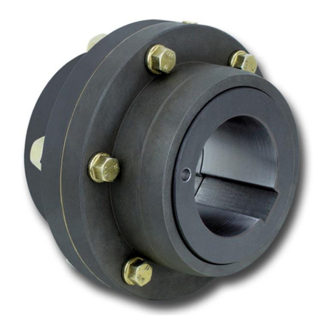
The main task of the elastic jaw coupling consists in transferring the torque of one shaft
end onto another element. Additionally, the coupling is designed to compensate angular,
radial and axial misalignments and reduce the intensity of vibrations and shocks.
1.2. General safety instructions
Safety takes the highest priority for all works with and on the coupling.
To ensure this, the following safety instructions must be observed:
- During installation and maintenance work, the drive motor must be secured against un-
intended start-up and the load side against turning back.
- Accidental touching of the coupling during operation must be prevented with a suitable
cover or protective device.
- Do not reach into the working area of the coupling during operation.
1.3. Other applicable provisions, standards etc.
The couplings are designed on the basis of DIN 740, part 2 (see RINGSPANN catalogue
“shaft coupling”). If the operating conditions (e.g. output, speed) should change, the original
design of the coupling must be reviewed along with the load-bearing capacity of the shafts
and the used shaft-hub-connections.
The locking screws are in compliance with DIN EN ISO 4029.
1.4. Classification in accordance with EC Machinery Directive 2006/42/EC
The couplings type REK … DGO/…DHO/…DGZ are a machine element. Since machine
elements do not fall under EC Machinery Directive 2006/42/EC, RINGSPANN does not
draw up a declaration of incorporation. All important information with regards to the installa-
tion, commissioning and operation is explained in the following.
2. Design and function / parts list
2.1. Labelling
Depending on the coupling size, the parts are labelled as follows:
Hubs:
- RINGSPANN logo
- Abbreviated designation
Elastomer elements:
- RINGSPANN logo
- Size designation
Spacer and driver
- RINGSPANN logo
- Abbreviated designation
- Marks for mounting position
