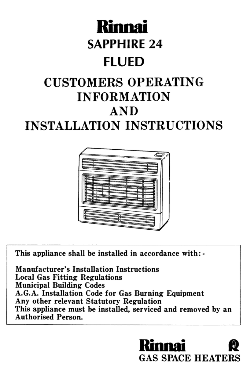
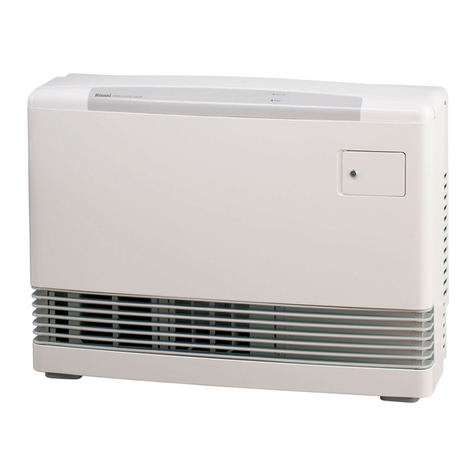
Front Panel Removal
The front panel is held in position by four screws, one at either end of the
top louvre and at either end of the underside of the base panel. After
removing all screws ease the panel straight forward clear of the heater.
TF Model Only
An earthed power point is required within 1.5m from the heater.
TESTING PROCEDURE
After clearing .a11swarf and purging the gas supply to the heater, connect
the gas and check for leakage at connections.
Check Burner Pressure
Turn knob to ignition position to light burner. If burner fails to light,
repeat. The heater is fitted with a flame failure valve included in the gas
valve. Hold valve in the ignition position for 20 seconds and then release.
The heater should continue to operate. If burner goes out check position
of thermocouple in flame and repeat ignition procedure.
Turn control to “Off” position. Remove test point screw and attach
manometer. Light unit in usual way. Leave full on and check pressure.
Reset pressure by adjusting regulator screw if necessary. Regulator is
situated on the side of the gas cock assembly. Check the supply pressure
before making adjustments to unit as the regulator has been factory preset.
Turn control to “Off” position before removing manometer. Replace the
test point screw. Pilot gas rate cannot be adjusted. Turn heater on and off
again a few times to check ignition.
Fan - TF models only
Connect power lead to wall socket and switch on power. Move heater fan
switch to on position and check operation of fan.
Fault Failure Procedure
If you cannot get the heater to work properly, contact Rinnai NZ Ltd, their
nearest Service Centre or Gas Utility.
INSTRUCT CUSTOMER IN USE AND CARE OF THE HEATER
Make sure the customer understands the instructions.
*
3.
4.
SERVICING INSTRUCTIONS
Rinnai recommend your Cosypanel heater is serviced every year.
1. Multifunctional Gas Valve incornoratincr oiezo ianition,
regulator and flame failure safetv device
This valve is designed as a sealed unit and as such it should not be
? $s.isnan;~d except to replace the flame failure safety device magnetic
2. Thermocounle
The thermocouple may be replaced b
t: removin
from it’s mounting bracket above the %the thermocouple
urner an releasinq the
connector from the gas valve.
Burner and Injector
Remove the mounting screw from the left hand end of the burner and
slide burner sideways clear of the injector. The injector may now be
unscrewed if required.
Gas Valve
Turn off
from walP
as supply and disconnect from heater. Remove the heater
and remove screws from the valve mounting bracket, two
from rear panel and one from burner chamber.
Release thermocouple, pilot tube, gas supply pipe and piezo ignition
lead. Lift the valve clear of the heater.
Description SPECIFICATIONS
-
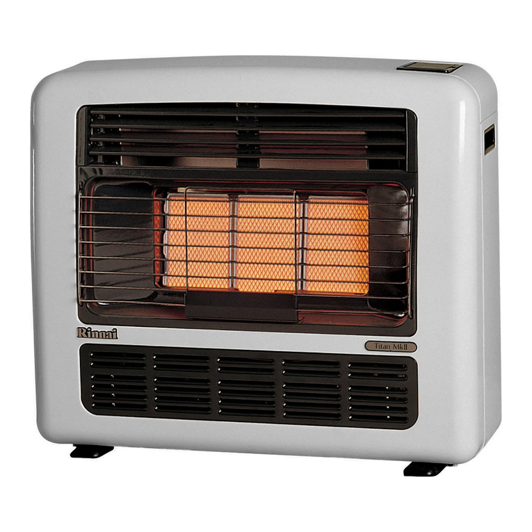
- Rinnai Cosypanel R800 / 501T convector wall
heater
Type -
Description -
Type -
Input -
Gas Control -
Burner
Test Point Pressure -
Gas Inlet
Ignition -
Injectors and Gas Rate -
Dimensions -
Electric Supply -
Fan -
6 7
Natural convection
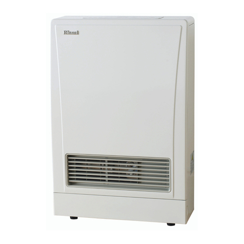
Rinnai Cosypanel R800 / 501TF convector wall
heater with fan
Natural or forced convection
R800 NG 8.0 MJ/h R501 NG 5.3 MJ/h
Rinnai multi-functional one touch gas valve
Aeromatic single entry
NG only 1.0 kPa.
Flare fitting to suit 1Omm O.D. copper pipe
Piezo electric
Please see data plate LH side of front panel
Width 540mm, height 390mm, depth 128mm
over mounting bracket
(TF only) 230~ 50Hz A.C. only 0.06 AMP
(TF only) Royal 40mm single speed


