Rinnai PATIOSSL User manual

Patio Heater
Operating and Installation Instructions
Model No PATIOSSL
IMPORTANT
This appliance shall be installed in accordance
with:
• Manufacturers Installation Instructions.
• Local Gas fitting regulations.
• Municipal Building codes.
• AGA Gas Installation CodeAG601 - NZ 5261.
• Any other relevant statutory regulation.
For Outdoor Use Only
LP Gas Only
FEATURES
• Completely self contained
• High efficiency radiant plaques
• Stainless steel construction
• Battery ignition
• Safety shutdown on tip over
• 25 MJ/hr. input
• Approximately 20 hours operation from a
properly filled 9 Kg cylinder
Retain these instructions for future use
Please read these instructions fully before
assembling or operating the appliance
zx

2
IMPORTANT NOTES
IMPORTANT
THIS APPLIANCE SHALL NOT BE
INSTALLED OR USED INDOORS.
DO NOT PLACE ARTICLES ON OR
AGAINST THIS APPLIANCE.
DO NOT USE OR STORE FLAMMABLE
MATERIALS NEAR THIS APPLIANCE
DO NOT SPRAY AEROSOLS IN THE
VICINITY OF THIS APPLIANCE WHILE IT IS
IN OPERATION
CHILDREN AND ADULTS SHOULD BE
ALERTED TO THE HAZARDS OF HIGH
SURFACE TEMPERATURES
This appliance is not intended for use by
young children or the infirm without
supervision.
Any materials or objects that are stored
near this appliance when it is in operation
may be subjected to radiant heat and could
sustain damage.
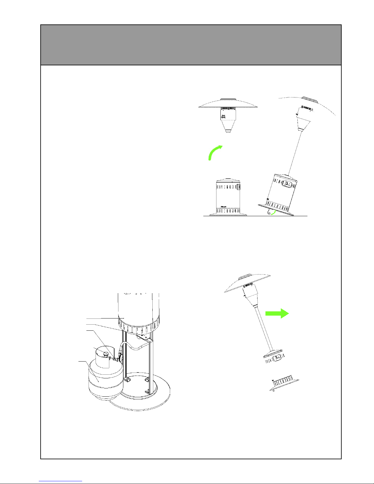
The gas supply hose is to be inspected for
damage before each use. Care must also
be taken not to damage the gas hose when
assembling the appliance and when fitting
or removing the gas bottle and bottle cover.
In the event of damage being evident
(cracks, tears, abrasion etc.), the hose must
be replaced immediately by an authorised
repairer.
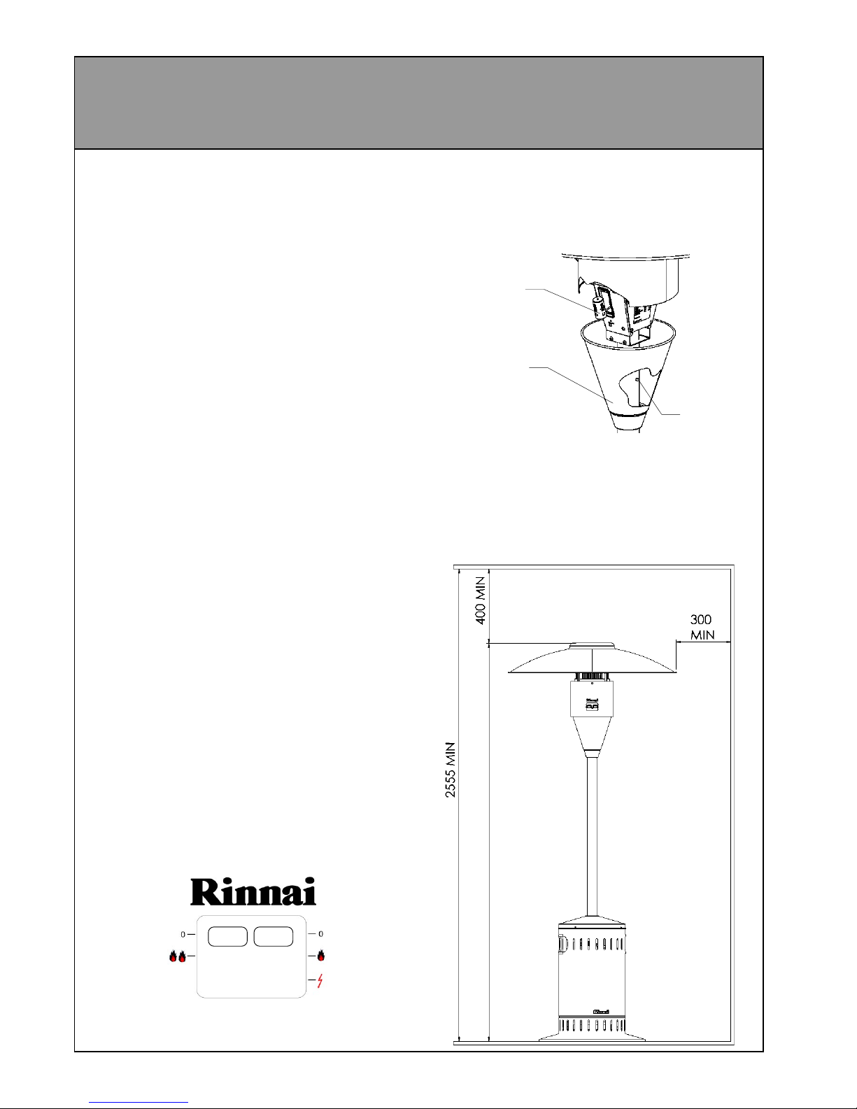
Care must be taken to ensure that the
minimum clearances shown on page 3 are
maintained.
This appliance should be serviced by a
qualified person on an annual basis.
All external covers are made from stainless
steel that will not rust but should be cleaned
regularly, especially if in a coastal
environment.
Stainless steel should be cleaned using
warm water and a mild detergent.
CAUTION: Never use products containing
abrasive liquid cleaners etc.
This appliance should be stored out of the
weather if not intended for use for long
periods of time.
To avoid damage to this appliance, the
battery should be removed when not being
used for long periods of time.

3
OPERATION
After the heater is properly assembled and all
gas connections to the regulator have been
tested for gas tightness (Refer page 9, To test
for gas tightness.), the heater is ready for
operation.
Connecting gas bottle:
1 Slide the bottle cover up until it is clear of
the leg assembly and rests on top of legs
so that it will not fall down while you are
installing the bottle.
2 ALWAYS CHECK THE GAS SUPPLY
HOSE FOR DAMAGE BEFORE
PROCEEDING AND HAVE THE HOSE
REPLACED IF THERE ARE ANY
CRACKS, HOLES, ABRASION MARKS
OR SIGNS OF PERISHING.
3 Attach the regulator to the bottle NOTE: the
thread on the regulator tightens by turning
counter-clockwise.
4 Fully open the valve on the gas bottle and
check the connection for leaks as described
in the assembly instructions.
5 Replace the bottle cover so that it is resting
completely on the base, taking care not to
trap the gas supply hose against the legs.
Bottle cover
Leg flange
Gas bottle
Valve
Regulator
Moving the heater
1 With the controls facing towards you, tip the
heater backwards.
2 Fold the wheels outwards as shown and
lower the lifted edge onto the wheels.
3 Tip the heater back in the opposite direction
until the heater is balanced and move to
desired location.
4 To retract the wheels simply push the heater
backwards again until the wheels are
hanging straight down and stand the heater
back up (the wheels should fold away without
any further assistance).
5 NOTE: The heater will not light unless the
wheels are retracted
IMPORTANT: YOU MUST TEST THIS
CONNECTION FOR GAS TIGHTNESS
BEFORE OPERATING THE HEATER.
Refer page 9, To test for gas tightness.

4
OPERATION CONTINUED
Lighting the heater
Once the heater is properly assembled and has
been checked for leaks, it is ready for
operation.( Refer page 9, To test for gas
tightness.)
1 Place the heater outdoors and ensure that the
minimum clearances to combustible materials
are met. (See pages 5 and 6, for definition of
outdoor area)
2 Make sure the heater is sitting on a firm flat
surface with the wheels retracted and all the
guards are in place, with the bottle cover sitting
on the base. NOTE: The heater will not start if
it is not standing straight up.
3 Check that both control knobs are in the off
(0) position.
4 Fully open the valve on the gas bottle.
5 Press and hold the ignition (right hand ) knob
down to the ignition symbol. You should hear
a ticking noise from the spark ignition. If there
is no sound then check that the battery is
properly installed and has a charge.
6 When the main burner has ignited then hold
the knob down for a further 15 seconds to
maintain ignition.
7 Once ignition has been established the
second control knob can be used to control
the top burner
8 If the burner fails to ignite or stay alight then
wait at least 5 minutes before trying again.
Shutting down the heater
1 To turn the heater off, close the valve on the
gas bottle.
2 Once the flame has extinguished, set both
control knobs to the off position.
To p
Burner
off
on
Main
Burner
off
on
ignition
(2155)
Changing the battery
Press the release button on the back of the pole
and slide the battery cover down to allow access
to the battery. Replace using a C size battery
only.
Minimum clearances
This appliance must not be operated unless the
following distances are maintained between the
heater and any combustible material
Ensure that any curtains or shade cloths etc. are
secured and will not get near the heater.
Release
button
Battery
cover
Battery

5
OUTDOOR AREA
Definition of an outdoor area
The following diagrams show the definition of an outdoor area (as described inAG405) . This appliance
must not be operated in a confined space that does not meet these requirements.

6
OUTDOOR AREA CONTINUED

7
Tools you will require
Adjustable spanners (or 2 x 13 mm spanners
and 1 x 19 mm spanner)
Phillips screwdriver
Paint brush with soap solution
4 mm hex allen key (supplied, attached to
burner)
IMPORTANT
Before proceeding with assembly of your patio
heater, unpack all the boxes and be sure that
you can identify all the parts shown below.
Note:
The legs and leg flange have been bolted
together for shipping purposes and will need to
be separated before assembly can begin.
There is also a rubber edging strip around the
lower rim of the burner tube**. This will need to
be removed before assembly. The rubber
edging around the leg flange must stay in place
to help prevent damage to the gas supply hose.
Pole
Base
complete with
wheels
Leg Flange
Leg
x 3
Burner
Hood
Bottle cover
Regulator
M8 x 20 bolt (6)
M8 nut (6)
Self tapping Phillips head
screw (2)
Stainless steel
button head cap screw (4)
ASSEMBLY INSTRUCTIONS
**

8
ASSEMBLY CONTINUED
1 Place the base on a flat surface, making
sure that the wheels are folded away
underneath the base.
2 Remove 1 bolt from the base and, using the
same bolt, attach 1 of the legs as shown
(do not re-tighten the bolt fully at this stage)
CAUTION: DO NOT REMOVE MORE
THAN 1 BOLT AT A TIME
3 Once all three legs are in place, attach the
leg flange to the top of the legs using the
M8 x 20 bolts and nuts. You can now fully
tighten the bolts in both the base and the
leg flange.
4 Slide the stainless steel pole over the leg
flange and attach using BOTH self
tapping screws. Take care not to over-
tighten the screws, as this may strip the
threads.
5 Slide the stainless steel
bottle cover assembly over
the pole, then remove the
protective rubber strip from
the end of the burner
assembly spigot tube.
Remove the battery cover
from the burner assembly
and slide it over the pole as
well.
6 Carefully hold the burner
support and feed the gas
supply hose down the pole
until it protrudes through the
leg flange.
7 Slide the burner assembly
spigot tube inside the pole.
You will need to depress the
small silver button on the
back of the spigot tube to
allow the assembly to slide
down fully. (Take care not to
pinch fingers)
8 Once the assembly is
inserted, you may need to
rotate it until the silver button
protrudes from the pole.
M8 x 20 Bolt Leg
Leg Flange
M8 x 20 Bolts
M8 nuts
Stainless steel
pole
2 x self tapping
screws
Battery cover

9
9 Remove the plastic wrap from the burner
assembly and carefully place the hood on
top of the burner assembly as shown
below, and align the four holes in the hood
with the chrome rods on the burner
assembly.
10 Using the 4 mm allen key (this is held by a
plastic clip on the side of the burner
assembly) attach the hood using the
stainless steel button head cap screws. Do
not tighten the screws until all four are in
place. You may need to tilt the unit over or
use a step ladder to attach the hood.
11 Remove the plastic tag from the end of the
battery terminal and slide the battery cover
up until it passes the button on the pole.
M6 x 12
Button-head
cap screw
Chrome bar
4 mm Allen key
stored on side
of burner assembly
under battery cover
Gas supply hose
Regulator
Paint brush
with soap solution
12 Attach the gas supply hose (refer page 3,
connecting gas bottle) to the regulator and
tighten using a spanner.
IMPORTANT: YOU MUST TEST THIS
CONNECTION FOR GAS TIGHTNESS
BEFORE OPERATING THE HEATER.
Release
button
Battery
Transit
tag
Battery
cover
To test for gas tightness:
1 Fit the regulator to a properly filled gas bottle
and tighten by hand. (Note: turn fitting counter-
clockwise to tighten)
2 Fully open the valve on the gas bottle.
3 Using a brush or spray bottle, apply a solution
made up of liquid soap and water to all gas
connections to the regulator.
4 If bubbles appear then there is a leak .
5 If a leak is detected you must shut off the valve
immediately. Re-tighten the leaking connection
and re-test. If a leak is still detected then
contact the retailer where the appliance was
purchased from or an approved service
technician.

10
TECHNICAL SPECIFICATION
Model: PATIOSSL
Description: Stainless steel,
radiant plaque,
gas patio heater.
Input:: 25 MJ/hr.
Gas control: Rinnai lever control
combination
Burner: Radiant plaque
Regulator: POL (2.74 Kpa)
Test point pressure 2.55 kPa
Gas type: LPG
Ignition: Battery spark
Battery: 1.5 V c-size
Outer materials: 304 Stainless steel
Frame materials: Gold pasivated
steel
Wheels: Rubber
Data Plate: Back panel under
battery cover
Weight : (without bottle) 30 kg
Table of contents
Popular Patio Heater manuals by other brands

Bodenheizung 24
Bodenheizung 24 LDHR1503 quick start guide

EUROM
EUROM TH2003 Instruction booklet

Paramount Fitness
Paramount Fitness KLD7002S instruction manual

Zanussi
Zanussi ZTPTH1 MANUAL & SAFETY INSTRUCTIONS

Nexgrill
Nexgrill 920-0010 Installation instructions and owner's manuals

Bond
Bond DLJ-A1 quick start guide

Red Stone
Red Stone PG139HC user manual

BlueRhino
BlueRhino Endless Summer 91000 owner's manual

Firesense
Firesense 1031510 Assembly / care & use instructions

SunStar
SunStar GLASS SGL35-N7-MG Installation and operation instruction

SereneLife
SereneLife SLOHT40 user manual

SunStar
SunStar PHS40 Assembly instructions and owner's guide