manuals.online logo
Brands
  1. Home
  2. •
  3. Brands
  4. •
  5. RITE-HITE
  6. •
  7. Automobile Accessories
  8. •
  9. RITE-HITE Wheel-Lok MWL-1300 User manual

RITE-HITE Wheel-Lok MWL-1300 User manual

MWL-1300 Wheel-LokTM
Vehicle Restraint
Installation Manual
This Manual Covers Restraints Built After Serial Numbers:
10HG900001M and up
PRINTED IN U.S.A.
RITE-HITE PRINT SHOP
PUBLICATION NO. 1301
NOVEMBER 2014
MADE IN U.S.A.
2Pub. No. 1301 - November 2014
RITE-HITE®MWL-1300 Installation Manual
TABLE OF CONTENTS
NOTICE TO USER. . . . . . . . . . . . . . . . . . . . . . . . . . . . . . . . . . . . . . . . . . . . . . . . . . . . . . . . . . . . . . . . . . . . . . . . . . . . . 2
SAFETY WARNINGS. . . . . . . . . . . . . . . . . . . . . . . . . . . . . . . . . . . . . . . . . . . . . . . . . . . . . . . . . . . . . . . . . . . . . . . . . . . 3
INSTALLATION INSTRUCTIONS . . . . . . . . . . . . . . . . . . . . . . . . . . . . . . . . . . . . . . . . . . . . . . . . . . . . . . . . . . . . . . . . . 4
WARRANTY . . . . . . . . . . . . . . . . . . . . . . . . . . . . . . . . . . . . . . . . . . . . . . . . . . . . . . . . . . . . . . . . . . . . . . . BACK COVER
NOTICE TO USER
Your local Rite-Hite representative provides a Planned Maintenance Program (P.M.P.) which can be fitted to your
specific operation. Call your local representative or the Rite-Hite at 414-355-2600.
The Rite-Hite products in this manual are covered by one or more of the following U.S. patents: 5,546,623;
5,553,987; 5,582,498; 5,664,930; 5,702,223; 5,762,459 (RE: 37,570); 5,882,167; 6,065,172; 6,070,283; 6,085,375;
6,089,544; 6,092,970; 6,106,212; 6,116,839; 6,190,109; 6,276,016; 6,311,352; 6,318,947; 6,322,310; 6,360,394;
6,368,043; 6,431,819; 6,488,464; 6,499,169; 6,505,713; 6,520,472; 6,524,053; 6,634,049; 6,726,432; 6,773,221;
6,832,403; 6,880,301; 7,032,267; 7,062,814; 7,134,159; 7,213,285; 7,216,391; 7,363,670; 7,380,305; 7,503,089;
7,533,431; 7,546,655; 7,584,517; 7,681,271; 7,823,239; 7,841,823; 7,877,831; 7,914,042; 8,006,811; 8,065,770;
8,141,189; 8,191,194; 8,286,757; 8,287,223; 8,303,235; 8,307,956; 8,443,474; 8,464,384; 8,464,846; 8,465,245 and
pending U.S and foreign patent applications. RITE-HITE®, THINMANTM, SAFE-T-LIP®, HYDRACHEK®, WHEEL-LOKTM,
DOK-LOK®, DUAL-DOK®, SAFE-T-STRUTTM, DOK-COMMANDER®, JUMBOTM, HYDRA-RITETM, SAFE-T-GATE®, RITE-
VUTM LIGHT COMMUNICATION SYSTEM and SMOOTH TRANSITION DOK SYSTEMTM, are trademarks of Rite-Hite®.
Pub. No. 1301 - November 2014 3
RITE-HITE®MWL-1300 Installation Manual
SAFETY WARNING
XXXXXXXXXXXX
XXXXXXXXXXX
OPERATE
DO NOT
LOCKOUT/TAGOUT PROCEDURES
The Occupational Safety and Health Administration requires that, in addition to posting safety warnings and
barricading the work area, the power supply has been locked in the OFF position or disconnected. It is mandatory
that an approved lockout device is utilized. An example of a lockout device is illustrated. The proper lockout
procedure requires that the person responsible for the repairs is the only person who has the ability to remove the
lockout device.
In addition to the lockout device, it is also a requirement to tag the power control in a manner that will clearly note
that repairs are under way and state who is responsible for the lockout condition. Tagout devices have to be
constructed and printed so that exposure to weather conditions or wet and damp locations will not cause the tag to
deteriorate or become unreadable.
RITE-HITE®Corporation does not recommend any particular lockout device, but recommends the utilization of an
OSHA approved device (refer to OSHA regulation 1910.147). RITE-HITE®Corporation also recommends the review
and implementation of an entire safety program for the Control of Hazardous Energy (Lockout/Tagout). These
regulations are available through OSHA publication 3120.
When working with electrical or electronic
controls, make sure that the power source has
been locked out and tagged according to OSHA
regulations and approved local electrical codes.
This is the highest level statement. Failure to
follow the listed instructions will most likely
result in severe injury or death.
IMPORTANT is used to draw attention
to a procedure that needs to be followed to
prevent machine or property damage.
This is a statement of serious hazard. Failure to
follow the listed instructions could place the
individual at risk of serious injury or death.
The statements used with this level of
warning deal with a safe operating
procedure. If the procedure is ignored, the
possibility of personal injury may exist.
4Pub. No. 1301 - November 2014
RITE-HITE®MWL-1300 Installation Manual
INSTALLATION INSTRUCTIONS
The performance of any machine can be no better than
the installation and application. The MWL-1300 vehicle
restraint requires only ordinary application and
installation skills using good workmanship and quality
materials.
Follow the 6-step Installation Procedure:
1. Inspect components.
2. Install frame assembly.
3. Install wheel guides.
4. Install electrical components and signs.
5. Install conduit guard.
6. Test operation.
INSPECT COMPONENTS
Open and inspect all materials. Immediately report any
damage or material shortage. Study component
assemblies and determine their proper locations.
MWL-1300 VEHICLE RESTRAINT POWER
SOURCE
On occasion, the incoming electrical power for the
MWL-1300 vehicle restraint is taken from a convenient
nearby electrical appliance, i.e., overhead door opener.
Generally, there is no problem using this sort of power
source; you must, however, verify that the amperage is
in accordance with local and federal codes.
The MWL-1300 vehicle restraint requires 120V, single
phase 60 Hz power and 1 amps of current. Ten (10)
MWL-1300 vehicle restraints can be hooked into one (1)
20 amp feeder circuit per the current N.E.C. Paragraph
#430-53.
WHEN IN DOUBT, CALL YOUR LOCAL RITE-HITE
REPRESENTATIVE OR RITE-HITE AT (800) 456-0600.
Post safety warnings and barricade work area,
at dock level and at ground level, to prevent
unauthorized use of the dock position. When working with electrical or electronic
controls, make sure that the power source has
been locked out and tagged according to OSHA
regulations and approved local electrical
codes.
All components must be connected to a
SAFETY EARTH GROUND where indicated. The
SAFETY EARTH GROUND must conform to the
current National Electric Code Section 250-81
section (a) or section (c) for a grounding
electrode system.
Pub. No. 1301 - November 2014 5
RITE-HITE®MWL-1300 Installation Manual
INSTALLATION INSTRUCTIONS CONTINUED
CONCRETE APPROACH REQUIREMENTS
Verify the approach meets the following criteria:
1. The approach must be concrete, 161" wide by 258"
long x 6" minimum thickness. See Figure 1.
2. If longer optional wheel guides are to be used, the
pad length must be increased to 318" from dock
face.
3. The approach must be free of discontinuities (such
as cracks, potholes, etc.). Approach must not
protrude more than 1/2” above the bottom of base
plates at any point where the barrier comes to rest.
See Figure 2.
4. The MWL-1300 vehicle restraint can be installed
and shimmed up to 1" without modification. If
greater than 1" of shimming is necessary, longer
anchors will be required. Please consult RITE-HITE.
TRENCH DRAINS
1. If the trench drain lies in the same position as a
MWL-1300 vehicle restraint anchor plate, a steel
plate must be welded to the mounting pad and
anchored to the approach. See Figure 2.
161"
(13'5")
258" (21'6")
Dock
Face 70"
C
L
91"
FIGURE 1 - CONCRETE PAD
RIGHT SIDE ORIENTATION SHOWN
(LEFT SIDE ORIENTATION OPPOSITE)
Never weld on the MWL-1300 vehicle restraint
when the electrical components are connected
to the main control box and the power to the
box is “ON”. Electrical current from the welder
can “FEED BACK” through the circuit and
could cause injury or damage electrical
components.
6Pub. No. 1301 - November 2014
RITE-HITE®MWL-1300 Installation Manual
Side View
Top View
Additional Plate Welded To Base
Plate When Base Plate Bridges
A Trench Drain. See Note 2
Plate For Center Support Not
To Protrude Into Tire Path.
TYP
1/4”
Trench Drains
Dock Face
Approach
C
L
1/2” Allowable
Shim Center Base Plate
Trench
Drains
Dock Face
Shim Beneath MWL Base
Plates As Required
FIGURE 2 — INSTALLATION OVER A TRENCH DRAIN AND SHIMMING
INSTALLATION OVER A TRENCH DRAIN AND SHIMMING INSTRUCTIONS
INSTALLATION INSTRUCTIONS CONTINUED
Pub. No. 1301 - November 2014 7
RITE-HITE®MWL-1300 Installation Manual
INSTALLATION INSTRUCTIONS CONTINUED
LOCATE THE CENTERLINE
1. Secure a 20' length of string at the lower right edge
of the dock leveler pit at the dock face. Measure out
5' of string, and holding a piece of chalk at the end
of the 5' length of string, draw a large arc which
begins well before and extends past where you
expect the centerline to be. See Figure 3.
2. Repeat Step 1, this time beginning at the lower left
edge of the dock leveler pit at the dock face. Where
the two arcs intersect indicates one point of the
centerline.
3. Repeat Steps 1 and 2, using 20' of string instead of
5'. Use the intersections of both arcs as points to
snap a chalk line. This line is the centerline (Line A)
for the frame assembly.
LOCATE FRAME POSITION
1. Measure to the right of the centerline 48-3/4". Snap
a chalk line for Line B. To ensure Line B is parallel
to the centerline (Line A), measure and mark at
several locations. See Figure 3.
2. Measure 22" off each bumper face. Snap a chalk
line for Line C. See Figure 3.
LIFTING INSTRUCTIONS
NOTE: DO NOT FORK BENEATH WHEEL GUIDE!
1. Place barrier at approximate mid section of wheel
guide and place in Locked position.
2. Route lifting strap around wheel guide and barrier
as shown in Figure 4 ensuring that the straps are
above the coil cord support cable.
POSITION FRAME
1. Position the MWL-1300 vehicle restraint along the B
and C lines as shown in Figure 5. The rear edge of
the rear mounting plate should be aligned with Line
C. The edge of the front and rear base plate should
be aligned with Line B. See Figure 5.
SHIM AND ANCHOR FRAME
1. Starting at one end of the frame assembly, see
Figure 2 for shimming instructions, drill anchor holes
using mounting plates as templates. Insert anchor
bolts, tapping each into the drilled holes with a
hammer so that the head of the anchor is as close
to the anchor plate as possible without causing the
frame to twist.
2. After all concrete anchors have been inserted, using
a torque wrench, tighten each to 60 ft-lbs of torque.
C
L
20 Ft. 20 Ft.
Line A
Line B
48-3/4”
5 Ft.
5 Ft.
Line C
Dock
Bumper
22”
Loading Dock
FIGURE 3 - LOCATING CENTERLINE
DO NOT Fork Beneath
Wheel Guide
Lifting Strap
Ref.
Ensure Lifting
Straps Are Above
The Coil Cord
Support Cable
DO NOT Fork Beneath
Wheel Guide
FIGURE 4 - LIFTING
8Pub. No. 1301 - November 2014
RITE-HITE®MWL-1300 Installation Manual
INSTALLATION INSTRUCTIONS CONTINUED
INSTALL WHEEL GUIDES
NOTE
If there is another loading dock on the right side of the
MWL-1300 vehicle restraint installation and this position
does not have wheel guides, it is required to install a
protective wheel guide. See Figure 5.
1. Measure 184” off of bumper face and snap a chalk
line.
2. Measure 78” and 75” off the centerline to the right
and snap chalk lines.
3. Position right wheel guide so left rear corner of
rear mounting plate is 184” from bumper face and
78” from centerline, and left rear corner of front
mounting plate is 75” from centerline.
4. Position left wheel guide so left rear corner of rear
mounting plate is 184” from bumper face and right
rear corner of rear mounting plate is 47.75” from
centerline. Position so that right rear corner of
front mounting plate is 50.75” from centerline.
5. Insert concrete anchors and tighten, using a torque
wrench to 60 ft-lbs.
LOCKING RANGE
These instructions are intended for ALL DOCK
PERSONNEL who are involved in loading/unloading
trucks and trailers. MWL-1300 vehicle restraint is a
safety system used to accommodate trucks and trailers
with tire diameters ranging from 30" to 44", while the
rear axle is located at a maximum of 145" away from
the face of the loading dock. See Figure 6.
Min.
43"
Max.
145"
FIGURE 6 - WHEEL POSITION RANGE
Always check that the vehicle is parked firm
against the bumpers before locking the
MWL-1300 vehicle restraint.
Loading Dock
22”
Line C
Edges Of
Front & Rear
Base Plates
Aligned With
Line B
184”
Typ.
Line A
Line B
78-1/4”
47-3/4”
75”
51”
48-3/4”
C
L
Protective Wheel
Guide Required
When There Is
Not A MWL
Installed At
Adjacent Dock
Position.
(Long Wheel
Guide Optional)
Dock
Bumper
Standard
Short
Wheel
Guide
Optional Long
Wheel Guide
52”
Optional Short
Wheel Guide
Opposite
Side
Wheel
Guide
Same
Side
Wheel
Guide
Adjacent
Dock
Wheel
Guide
FIGURE 5 - ANCHORING TRACK
Pub. No. 1301 - November 2014 9
RITE-HITE®MWL-1300 Installation Manual
INSTALLATION INSTRUCTIONS CONTINUED
48”
Approach
Loading Dock C
L
Door Opening
(Reference)
Floor
48”
18”
15”
Control
Box
Inside Caution
Sign
Some Docks May Have Truck Seals (Or Shelters)
Installed Or Planned Which Are Larger Than Standard.
Outside Light & Sign Location Mounting Should
Be Studied Before Proceeding To Avoid Interference.
Outside
Light Box
Outside Sign
(Mirror Text)
Operation
Sign
Outside
Sign
(Regular
Text)
7”
22”
58-1/2”
84-1/2”
96”
Junction Box NEMA 4 J.I.C.
Size Per Current NEC Section 370.16.
NOTE: Projection Of Box Not To Exceed 3.5”.
Right Side Orentation
(Left Side Orentation Opposite)
FIGURE 7 - ELECTRICAL INSTALLATION AND SIGN LAYOUT
When working with electrical or electronic
controls, make sure that the power source has
been locked out and tagged according to OSHA
regulations and approved local electrical
codes.
INSTALL ELECTRICAL COMPONENTS AND SIGNS
• When drilling holes in the box, DO NOT allow
the drill to go too deeply into the box.
Damage to the control systems may occur.
• DO NOT turn control box upside down to
drill any access holes. Cover internal
electrical components prior to drilling - this
will prevent debris from contacting the
internal electrical components.
• Remove all debris from box using a shop
vacuum. NEVER use air to blow debris from
the control box.
10 Pub. No. 1301 - November 2014
RITE-HITE®MWL-1300 Installation Manual
CONTROL BOX AND CONDUIT
INSTALLATION PROCEDURES.
1. Install the control box on a wall adjacent to the
overhead door at approximately 48" above the floor
level. See Figure 7.
2. Drill a hole for the power supply conduit (by others)
in the bottom of the control box. All holes drilled
through the control box must be through the
bottom of the box.
Control Box Installation Guidelines -
Temperature Controlled Applications.
a. Conduit should be routed to enter through the
bottom or side of the enclosure. A drip leg may be
needed if the conduit could fill with water.
b. Seal the conduit in any location where the conduit
transitions temperature zones that may produce
condensation.
c. Spacers should be installed between the enclosure
and the wall to provide tempature insulation and air
flow.
ELECTRICAL INSTALLATION
If the incoming electrical power for the MWL-1300
vehicle restraint is taken from a nearby electrical
appliance, i.e., overhead door opener, verify that the
amperage is in accordance with local and federal
codes.
The MWL-1300 vehicle restraint requires 120V,
single phase 60 Hz power and 1 amps of current.
Ten (10) MWL vehicle restraints can be hooked into
one (1) 20 amp feeder circuit per the current N.E.C.
Paragraph #430-53.
When in doubt, call your RITE-HITE representative
or RITE-HITE at (800) 456-0600.
The MWL-1300 vehicle restraint assembly includes
the control box with lights, outside power unit box
and the outside signal light box. The outside
junction box, conduit fittings and wire are provided
by others. Quality material and workmanship should
be used. Refer to Figure 7 for component location
information. Refer to electrical schematics found
inside the control box for wiring information.
All components must be connected to a
SAFETY EARTH GROUND where indicated. The
SAFETY EARTH GROUND must conform to the
1999 National Electric Code Section 250-50
section (a) or section (c) for a grounding
electrode system.
• The control box and all wiring should be
installed by a qualified electrician in
accordance with all national and local
electrical codes.
• If rigid conduit is installed, bonding must be
maintained between conduit connections by
using ground bushings and a jumper wire.
INSTALLATION INSTRUCTIONS CONTINUED
ELECTRICAL SCHEMATIC (STANDARD)
FROM CUSTOMER MAIN POWER &
SAFETY PROTECTION DEVICE.
(1L1)
(N)
SEQUENCE OF OPERATION NOTES:
- LATCH WILL BE ENGAGED WHEN THE RESTRAINT IS
ENGAGED. THIS WILL PREVENT THE RESTRAINT
FROM BEING DISENGAGED WITHOUT PRESSING
THE UNLOCK BUTTON.
SW1 "TIRE PEC" SENSOR
(WH)
(BN)
(BL)
NPN
CPU MODULE
+V1
SW1+
SW1-
+V2
SW2+
SW2-
SW3
OSPWR
OSG
OSR
FU1
OPTMOD
HARN
1
12
+12VDC
+12VDC
AMBR LT CNTRL
OSR SENSE
OSG SENSE
GND
GND
HS #3
HS #2
HS #1
LOCK
UNLK
RED
RED
YELLOW
WHITE/ORANGE
WHITE/GREEN
BLACK
BLACK
VIOLET
BROWN
GRAY
BLUE
WHITE
G
RISR INSIDE LT (OR)
12VDC, 0.54A
ISG INSIDE LT (GN)
12VDC, 0.54A
+12V COMMON (RD)
PB BOARD
SW2
"CHOCK LOCKED" SENSOR
(WH)
(BK)
H
H(-WH/BK)
(+WH/RD)
12VDC, 0.03
+(WH/RD)
OUTSIDE HORN
HORN-(WH/BK)
HORN+(WH/RD)
(2)
INSIDE HORN
N.O.
G
R
(OSPWR/42) COMMON
(OSG GREEN/41) 12VDC, 2.1A
(OSR RED/40) 12VDC, 2.1A
SW3
"CHOCK STORED" SENSOR
(WH) (BK)
N.O.H.C.
SW4
"TROLLEY STORED" SENSOR
(WH) (BK)
N.O.H.C.
(6)
12VDC, 0.03
(1) (3) (4) (5)
(1)
(3) (5)
(4)
(LO)
CPU MOD
UNLOCK
HS #2
LOCK
UNLOCK
HS #2
PUSH BUTTON BOARD
LOCK
ISA2
RG
HS #3
HS #1
RESTRAINT
CONTROLS
POWER MODULE STNDALN
20A 250V
SLOW BLOW
12FU
CONTROL
1A 250V
FASTBLOW
11FU
MOTOR
SOL CONTROL
1A 250V
FASTBLOW
17FU
F3
F1 F2
SOL1
SOL2
CR4
CR5
SCOM L1 L2 MCOM M1
SOL1(RD)
SCOM(RD)
(13)
CR4
(14)
2P, 120VAC
LOCK ACTUATOR RELAY
(12)
(4)
CR4-2
(8)
(9)
(1)
CR4-1
(5)
(RD) (BK)
SEE NOTE 2
L1
1FU1
1L1
FUSED DISCONNECT
(BY OTHERS)
G
N
DUMMY
N
SEE NOTE 8
110-120v. 1PH. 60HZ. USE 3.0A
DUAL ELEMENT TIME DELAY FUSES
NOTES:
1. Refer all installation and service to qualified personnel.
2. Refer to equipment owners manual for complete discription.
3. Power supply disconnect or protection device supplied at installation.
4. All field wiring to be minimum #14GA. 60°/75°C copper wire only, insulated sufficiently for incoming voltage.
5. All internal control box wiring to be #16GA. minimum 90°C copper wire, insulated sufficiently for incoming voltage.
NOTE: This does not include control harness.
6. Class 1 control circuit.
7. Use insulated 1/4" female spade connectors.
8. Torque requirements:
Contactor: 8.9-22 LB-IN (MIN-MAX)
Overload Relay: 16 LB-IN
Ground Terminal: 35 LB-IN
Terminal Block: 5.0-5.6 LB-IN (MIN-MAX)
Solid State Relay Terminal: 35 LB-IN
+V2(BU)
SW2-(BU)
(8)
SW2-(BU)
+V2(BU)
(7)
12VDC, 200mA ACTUATOR
MWL13 LOCK
(NOTE: REVERSE WIRING IF
DIRECTION IS BACKWARDS)
FIGURE 14 - ELECTRICAL SCHEMATIC (STANDARD)
Pub. No. 1301 - November 2014 11
RITE-HITE®MWL-1300 Installation Manual
12 Pub. No. 1301 - November 2014
RITE-HITE®MWL-1300 Installation Manual
ELECTRICAL SCHEMATIC (OPTIONS MODULE)
CPU
module
photoeye
inter-
connect
hydraulic
inter-
connect
raise
LEGEND
lable LED lamp
denotes field wiring
leveler/overhead door
stored interlock
mechanical/
FA inter-
connect
NOTE: Use included female spade
connectors for installation. 5631D029
unidox
inter-
connect
selector
switch
OFF ON
security
system
interface
output
unidox
inter-
connect
output
green
light
inter-
lock
output
option
module
power
module
NOTE: The standard wiring is not shown in this drawing to better show the option module wiring.
For information on standard wiring, see previous page.
20A 250V
SLOW BLOW
12FU
CONTROL
1A 250V
FAST BLOW
11FU
MOTOR
SOL CONTROL
1A 250V
FAST BLOW
17FU
F3
F1 F2
SOL1
SOL2
CR4
CR5
SCOM L1 L2 MCOM M1
M1
SOL1
SOL2
FIGURE 15 - ELECTRICAL SCHEMATIC (OPTIONAL)
Pub. No. 1301 - November 2014 13
RITE-HITE®MWL-1300 Installation Manual
INSTALLATION INSTRUCTIONS CONTINUED
The MWL-1300 vehicle restraint is now ready for the
initial test procedure, which must be carried out prior to
use of the device.
1. Move the barrier / carriage assembly from its
stored position at the rear of the unit and verify the
outside lights change to RED, inside lights should
remain RED.
2. Align barrier so that it is between spools and
engage over wheel guide and ensure the unit is
engaging the locking shaft. Place a hand over the
photo eye window. Outside lights should stay RED
and inside lights should change to GREEN.
3. If equipped with latch, verify pin extends into
barrier.
4. Remove hand momentarily from photo eye
window, alarm should sound. Replace hand over
window and alarm should silence.
5. With unit in a “safe locked” condition press “Do Not
Enter” button on control box. Inside lights should
change to RED and outside lights should be
flashing simultaneous RED / GREEN. This
indicates the restraint may be moved to its stored
position.
6. If equipped with latch, verify pin retracts out of
barrier.
7. Pull barrier from the tire path to rest on carriage
and move the barrier carriage assembly to its
stored position at the rear of the restraint. Outside
lights should change to RED.
Make sure that electrical schematics are in the control
box and that the working area is clean and free of any
packaging material.
If light sequence differs from what is described
above, check the electrical installation. If the
situation can not be resolved, call RITE-HITE for
assistance. NEVER leave the job site with the
MWL-1300 vehicle restraint not working
properly. Store the barrier in its rest position
before you leave the site.
TEST OPERATION
14 Pub. No. 1301 - November 2014
RITE-HITE®MWL-1300 Installation Manual
NOTES
Pub. No. 1301 - November 2014 15
RITE-HITE®MWL-1300 Installation Manual
NOTES
Global Sales & Service Office:
RITE-HITE
8900 N. Arbon Drive
P.O. Box 245020
Milwaukee, Wisconsin 53224
Phone: 414-355-2600
1-800-456-0600
www.ritehite.com
Representatives in all Major Cities
RITE-HITE STANDARD WARRANTY
Rite-Hite warrants that its products will be free from defects in design, materials, and workmanship for a period
of 365 days from the date of shipment. All claims for breach of this warranty must be made within 30 days after
the defect is or can, with reasonable care, be detected and in no event no more than 30 days after the warranty
has expired. In order to be entitled to the benefits of this warranty, the products must have been properly
installed, maintained, and operated within their rated capacities and/or specified design parameters, and not
otherwise abused. Periodic lubrication and adjustment is the sole responsibility of the owner. This warranty is
Rite-Hite’s exclusive warranty. RITE-HITE EXPRESSLY DISCLAIMS ALL IMPLIED WARRANTIES,
INCLUDING THE IMPLIED WARRANTIES OF MERCHANTABILITY AND FITNESS. Non-standard warranties,
if any, must be specified by Rite-Hite in writing.
In the event of any defects covered by this warranty, Rite-Hite will remedy such defects by repairing or replacing
any defective equipment or parts, bearing all the costs for parts, labor, and transportation. This shall be the
exclusive remedy for all claims whether based on contract, negligence, or strict liability.
LIMITATION OF LIABILITY
RITE-HITE SHALL NOT IN ANY EVENT BE LIABLE FOR ANY LOSS OF USE OF ANY EQUIPMENT OR
INCIDENTAL OR CONSEQUENTIAL DAMAGES OF ANY KIND, WHETHER FOR BREACH OF WARRANTY,
NEGLIGENCE, OR STRICT LIABILITY.

Other manuals for Wheel-Lok MWL-1300

2

Other RITE-HITE Automobile Accessories manuals

RITE-HITE Genisys GWC-1000 User manual

RITE-HITE

RITE-HITE Genisys GWC-1000 User manual

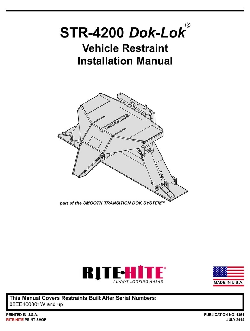
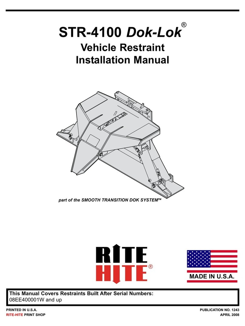
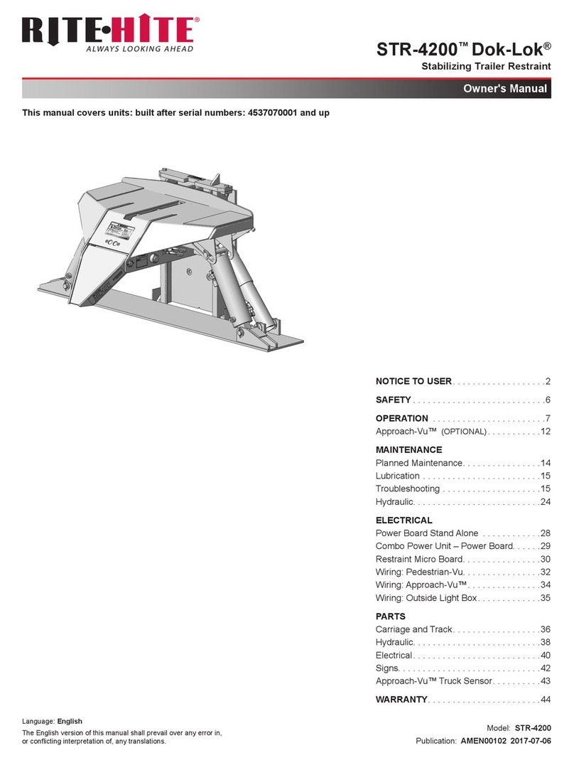
RITE-HITE STR-4200 Dok-Lok User manual

RITE-HITE

RITE-HITE STR-4200 Dok-Lok User manual

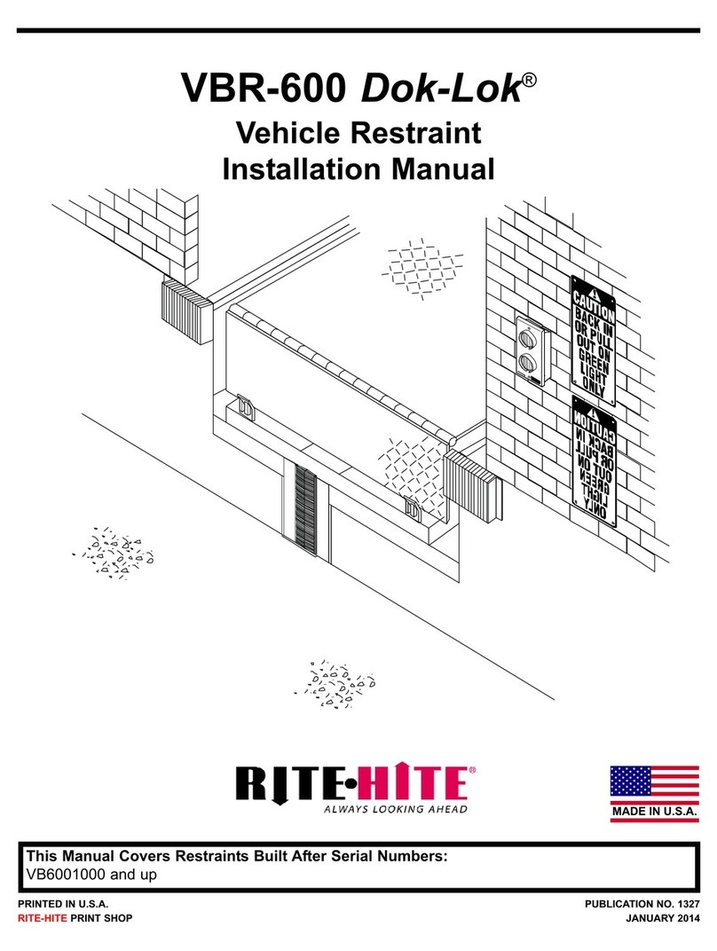
RITE-HITE DOK-LOK VBR-600 User manual

RITE-HITE

RITE-HITE DOK-LOK VBR-600 User manual

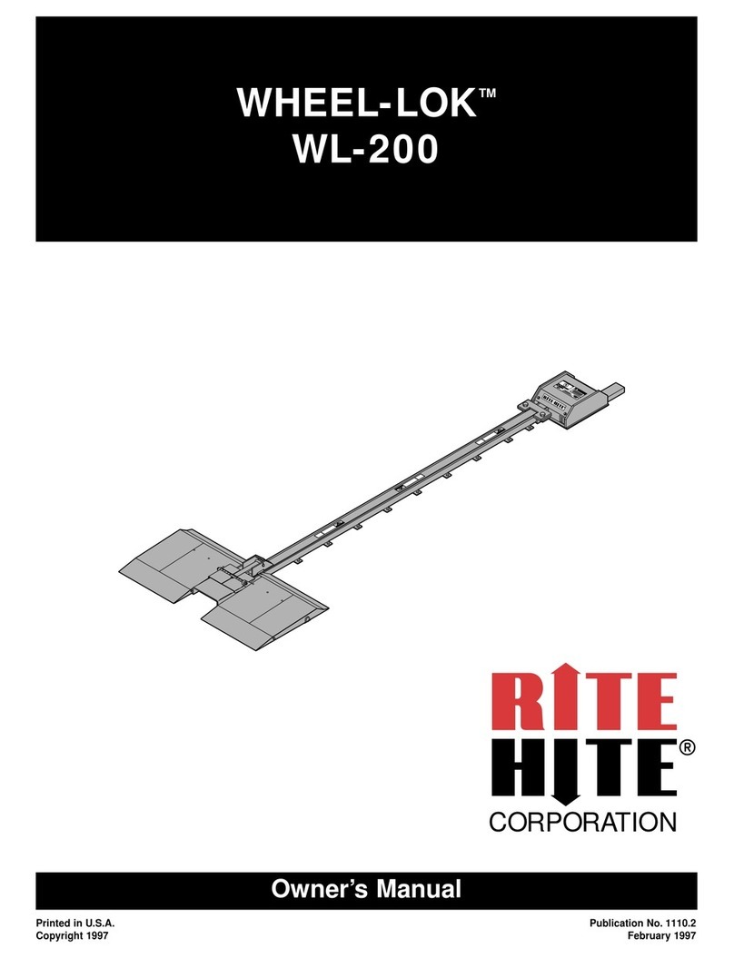
RITE-HITE WHEEL-LOK WL-200 User manual

RITE-HITE

RITE-HITE WHEEL-LOK WL-200 User manual

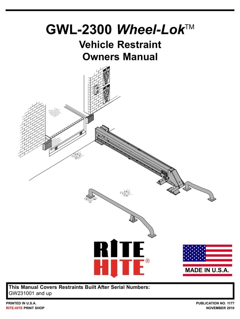
RITE-HITE Wheel-Lok GWL-2300 User manual

RITE-HITE

RITE-HITE Wheel-Lok GWL-2300 User manual

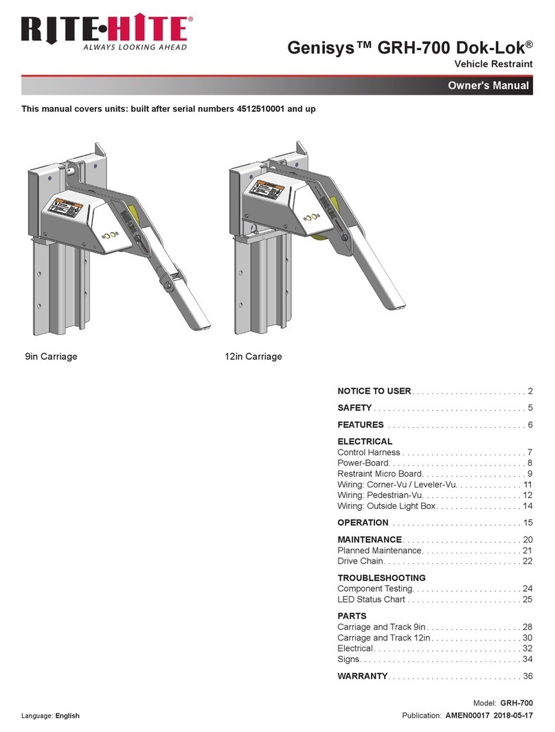
RITE-HITE Genisys GRH-700 Dok-Lok User manual

RITE-HITE

RITE-HITE Genisys GRH-700 Dok-Lok User manual

RITE-HITE Dok-Lok STR-4100 User manual

RITE-HITE

RITE-HITE Dok-Lok STR-4100 User manual

RITE-HITE VBR-300 Dok-Lok User manual

RITE-HITE

RITE-HITE VBR-300 Dok-Lok User manual

RITE-HITE STR-4200 Dok-Lok User manual

RITE-HITE

RITE-HITE STR-4200 Dok-Lok User manual

Popular Automobile Accessories manuals by other brands

Masterbuilt HITCH-HAUL 30111014 HHRB Assembly, care & use manual warning & safety information

Masterbuilt

Masterbuilt HITCH-HAUL 30111014 HHRB Assembly, care & use manual warning & safety information

FILTRON K 1296 Installation instruction

FILTRON

FILTRON K 1296 Installation instruction

Herd Aero installation guide

Herd

Herd Aero installation guide

Code Alarm TKRS1 installation guide

Code Alarm

Code Alarm TKRS1 installation guide

Canyon MagSafe CM-15 quick guide

Canyon

Canyon MagSafe CM-15 quick guide

Conceptronic ALTHEA03B Multi Language Quick Guide

Conceptronic

Conceptronic ALTHEA03B Multi Language Quick Guide

Yakima HangOut 2 manual

Yakima

Yakima HangOut 2 manual

Menabo YELO 4 NS Fitting instructions

Menabo

Menabo YELO 4 NS Fitting instructions

Accel ULTRA OPTI-SPARK II installation instructions

Accel

Accel ULTRA OPTI-SPARK II installation instructions

TrailFX 8457H manual

TrailFX

TrailFX 8457H manual

L&W FAB 4450063-1-1-2 installation manual

L&W FAB

L&W FAB 4450063-1-1-2 installation manual

Technaxx TE13 user manual

Technaxx

Technaxx TE13 user manual

DiscountRamps NDALR quick start guide

DiscountRamps

DiscountRamps NDALR quick start guide

Classic Instruments ULTIMATE installation manual

Classic Instruments

Classic Instruments ULTIMATE installation manual

Soundoff Signal MAGNUM H Installation

Soundoff Signal

Soundoff Signal MAGNUM H Installation

Hayman Reese 03404RW installation instructions

Hayman Reese

Hayman Reese 03404RW installation instructions

Road Ranger H392 installation manual

Road Ranger

Road Ranger H392 installation manual

Safe Fleet PRIME DESIGN DPS-8001 manual

Safe Fleet

Safe Fleet PRIME DESIGN DPS-8001 manual

manuals.online logo
manuals.online logoBrands
  • About & Mission
  • Contact us
  • Privacy Policy
  • Terms and Conditions

Copyright 2025 Manuals.Online. All Rights Reserved.