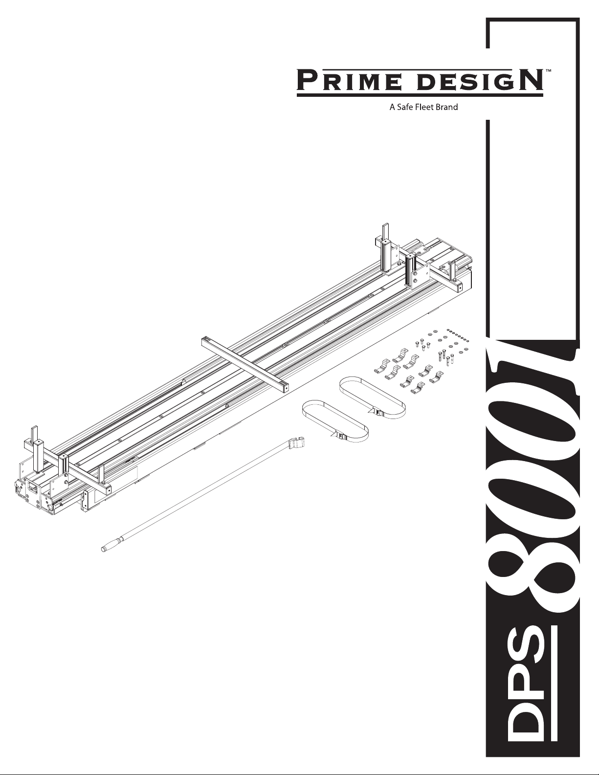
Safe Fleet PRIME DESIGN DPS-8001 User manual
Other Safe Fleet Automobile Accessories manuals

Safe Fleet
Safe Fleet Prime Design VRR FT31B User manual

Safe Fleet
Safe Fleet PRIME DESIGN HRR3-E-PM52 User manual

Safe Fleet
Safe Fleet PRIME DESIGN VBC-TC11B User manual

Safe Fleet
Safe Fleet Prime Design VCR-NV200 User manual

Safe Fleet
Safe Fleet PRIME DESIGN VRR3 CE User manual

Safe Fleet
Safe Fleet PRIME DESIGN VRR3-E-PM11 User manual

Safe Fleet
Safe Fleet Prime Design VBC NV200 User manual

Safe Fleet
Safe Fleet Prime Design FBM-1016-BLK User manual

Safe Fleet
Safe Fleet PRIME DESIGN FEA-0008 User manual

Safe Fleet
Safe Fleet Prime Design HRI3-E-FT33B User manual

Safe Fleet
Safe Fleet PRIME DESIGN VRR-CE11B User manual

Safe Fleet
Safe Fleet RVS systems RVS-M629 User manual

Safe Fleet
Safe Fleet Prime Design AR1418 User manual

Safe Fleet
Safe Fleet PRIME DESIGN HRR-269-E-UM3-96 User manual

Safe Fleet
Safe Fleet PRIME DESIGN VBC 226 User manual

Safe Fleet
Safe Fleet RVS systems RVS-M641 User manual

Safe Fleet
Safe Fleet PRIME DESIGN VBB PC11 User manual

Safe Fleet
Safe Fleet FRC SafeTrack Manual

Safe Fleet
Safe Fleet PRIME DESIGN HBR-E-FT32B User manual

Safe Fleet
Safe Fleet PRIME DESIGN VBR-226 User manual