7 EMHLB 0620
CLEANING & CARE OF YOUR LIGHTBAR:
Keeping the lenses clean and scratch free will optimize the performance of
the lightbar. The exterior of the lightbar including lenses should be cleaned
with mild soapy water and a soft cotton cloth to remove dirt, grime and
insects. Never use window cleaners or harsh chemicals on the lenses; this
may cause failure of the lenses or reduce clarity resulting in the reduction of
light output.
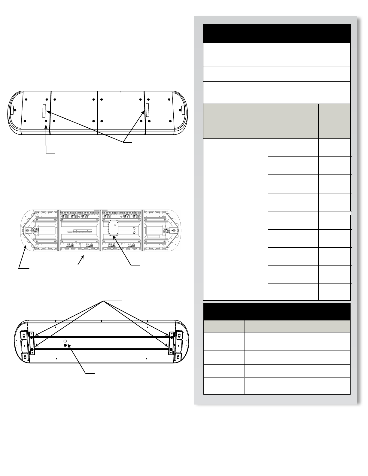
MOUNTING INTEGRITY:
A review of bolt/hardware/mounting bracket integrity should be performed
at the beginning and end of each shift.
WARNING - DRILLING ANY HOLES INTO THE LIGHTBAR IS NOT
RECOMMENDED! THE RISK OF DAMAGING INTERNAL COMPONENTS
AND THE RESULTING FAILURE OF THE LIGHTBAR WILL VOID ANY
WARRANTY OF THIS PRODUCT.
WARNING - CARE MUST BE TAKEN WHEN DRILLING THROUGH
THE ROOF OF THE VEHICLE NOT TO DRILL INTO ANY EXISTING
WIRING AND NOT TO DRILL THROUGH THE HEADLINER OR SUPPORT
MEMBERS OF THE VEHICLE. CHECK BOTH SIDES OF THE MOUNTING
SERVICE PRIOR TO DRILLING. DE-BURR ANY HOLES AND REMOVE
ANY METAL SHARDS OR REMNANTS. INSTALL GROMMETS INTO
ALL WIRE PASSAGE HOLES.
WARNING - ROUTE WIRES ONLY IN LOCATIONS THAT ARE NOT
SUBJECTED TO POTENTIAL WEAR. MAKE SURE TO AVOID ROUTING
WIRES IN THE DEPLOYMENT AREA OF YOUR AIR BAG. REFER TO
YOUR VEHICLE OWNER’S MANUAL FOR AIR BAG DEPLOYMENT
ZONES.
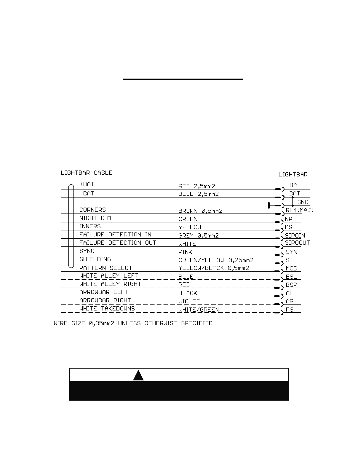
WARNING - ALL CUSTOMER SUPPLIED POWER WIRES CONNECTING
TO THE POSITIVE (+) OR NEGATIVE (-) BATTERY TERMINAL OR
LOCAL CHASSIS GROUND (-) MUST BE SIZED TO SUPPLY AT LEAST
125% OF THE MAXIMUM CURRENT AND PROPERLY FUSED AT THE
POWER SOURCE WITH APPROPRIATELY RATED FUSE.
IMPORTANT: When passing cables through re wall or other sheet
metal, insert grommet to protect the cable!
WARRANTY RETURN PROCESS:
Please contact your SoundOff Signal Sales Representative, Customer Services
staff or our Technical Department (800.338.7337) for a RMA #, Return
Merchandise Authorization Number.
The following information is required for issuance of the RMA #:
• Reason for returning the product*
• Address where replacement product is to be shipped*
• Telephone number where you may be reached*
• SoundOff Signal invoice number on which product was purchased**
• SoundOff Signal part number and serial number**
• E-mail address where RMA # should be e-mailed**
• Fax number where RMA # should be faxed**
* RMA # will not be given without this information.
** If available, please provide this information.
SoundOff Signal will NOT accept returns without an RMA #. Each RMA #
is good for only one (1) return and will expire (30) days after the date it was
issued. Products must be shipped back to SoundOff Signal and the RMA #
clearly marked on the outside of the package near the shipping label. Please
use the following address on your shipping label:
HOLOMYs.r.o.
ATTN: RMA # / Technical Services
Hemy 829
75701 Valasske Mezirici, Czech Republic
WARRANTY EXCLUSIONS:
Shipping & Handling, labor and service fees are non-refundable. SoundOff
Signal is not liable for any damage due to installation or personal injury as a
result of using SoundOff Signal product.
WARRANTY FORFEITURE:
Warranty will not be granted if the Warranty Return Policy & Procedure rules
are not strictly followed. Physical damage resulting from customer abuse
will void warranty. Warranty will also be voided if any SoundOff Signal and/
or manufacturer serial tags, product stickers, seals, or the like, are removed,
altered or tampered with. Returned product that is damaged by shipping via
the RMA # procedure is not the responsibility of SoundOff Signal.
Document effective date on cover and below supersedes previously dated
policies and statements.
There are no other warranties, expressed or implied, including, but not limited
to, any implied merchantability or tness for a particular use. SoundOff
Signal reserves the right to modify this warranty statement at any time; or to
discontinue, modify, or upgrade any products of its manufacture with design
improvements without prior notice.
WARNING MESSAGES - PLEASE READ:
WARRANTY & RETURN GOODS PROCEDURE
#EMHLB MAGNUM H™ H LED Lightbar