manuals.online logo
Brands
  1. Home
  2. •
  3. Brands
  4. •
  5. RITE-HITE
  6. •
  7. Automobile Accessories
  8. •
  9. RITE-HITE DOK-LOK VBR-600 User manual

RITE-HITE DOK-LOK VBR-600 User manual

VBR-600 Dok-Lok®
Vehicle Restraint
Installation Manual
This Manual Covers Restraints Built After Serial Numbers:
VB6001000 and up
PRINTED IN U.S.A.
RITE-HITE PRINT SHOP
PUBLICATION NO. 1327
JANUARY 2014
MADE IN U.S.A.
2Pub. No. 1327 — January 2014
RITE-HITE®VBR-600 DOK-LOK®Installation Manual
NOTES
Pub. No. 1327 — January 2014 3
RITE-HITE®VBR-600 DOK-LOK®Installation Manual
INTRODUCTION . . . . . . . . . . . . . . . . . . . . . . . . . . . . . . . . . . . . . . . . . . . . . . . . . . . . . . . . . . . . . . . . . . . . . . . . . . . 3
SAFETY WARNINGS . . . . . . . . . . . . . . . . . . . . . . . . . . . . . . . . . . . . . . . . . . . . . . . . . . . . . . . . . . . . . . . . . . . . . . . . 4
INSTALLATION. . . . . . . . . . . . . . . . . . . . . . . . . . . . . . . . . . . . . . . . . . . . . . . . . . . . . . . . . . . . . . . . . . . . . . . . . . . . . . . 5
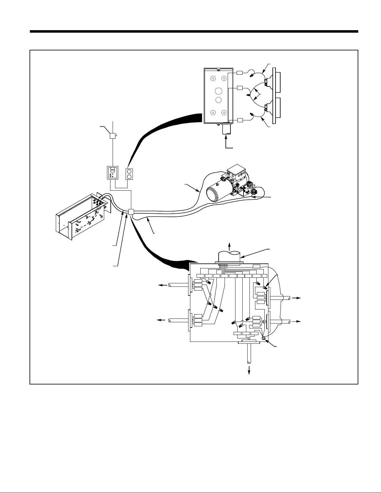
WIRING DIAGRAM FOR STAND ALONE DOK-LOKS . . . . . . . . . . . . . . . . . . . . . . . . . . . . . . . . . . . . . . . . . . . . . . . 8
ELECTRICAL SCHEMATIC FOR STAND ALONE DOK-LOKS. . . . . . . . . . . . . . . . . . . . . . . . . . . . . . . . . . . . . . . . . . 9
WIRING DIAGRAM FOR COMBINATION POWER UNIT DOK-LOKS . . . . . . . . . . . . . . . . . . . . . . . . . . . . . . . . . . . 10
ELECTRICAL SCHEMATIC FOR COMBINATION POWER UNIT DOK-LOKS. . . . . . . . . . . . . . . . . . . . . . . . . . . . . . 11
HYDRAULIC SCHEMATIC. . . . . . . . . . . . . . . . . . . . . . . . . . . . . . . . . . . . . . . . . . . . . . . . . . . . . . . . . . . . . . . . . . . . . . 12
WARRANTY . . . . . . . . . . . . . . . . . . . . . . . . . . . . . . . . . . . . . . . . . . . . . . . . . . . . . . . . . . . . . . . . . . . . . . . BACK COVER
TABLE OF CONTENTS
INTRODUCTION
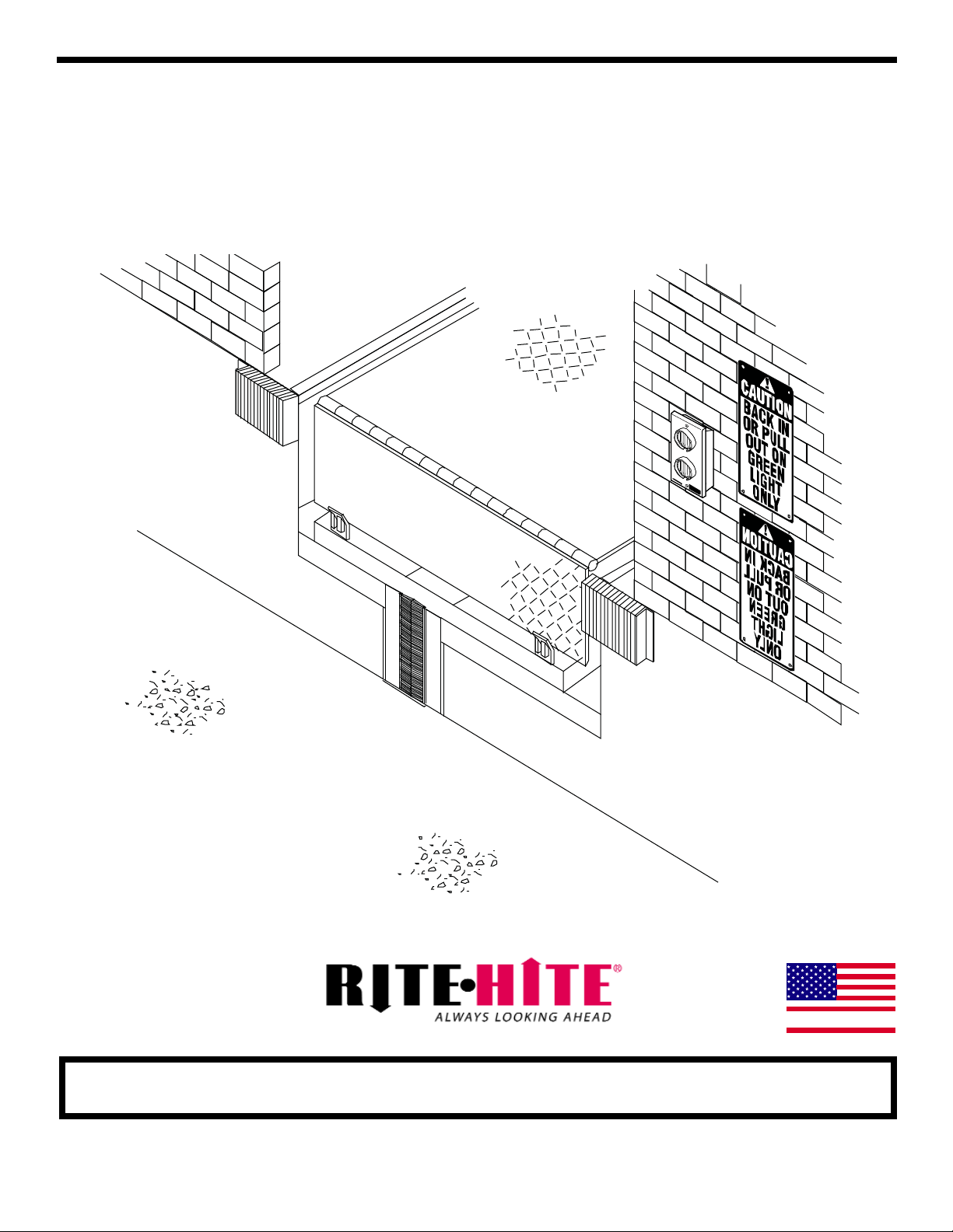
Read and understand this manual before attempting to install or operate any DOK-LOK vehicle restraint. For best
results, have this product serviced by your authorized Rite-Hite representative. The VBR-600 DOK-LOK vehicle
restraint by Rite-Hite is intended to provide a safer workplace for workers in shipping and receiving dock areas. The
VBR-600 DOK-LOK vehicle restraint is a hydraulic restraint device that, when properly installed and operated, retains
a secure connection between the truck and dock. Signal lights and signs provide instructions to the truck driver and
DOK-LOK vehicle restraint operator that a safe condition exists. The DOK-LOK vehicle restriant is operated by
pressing push buttons on an inside control panel.
NOTICE TO USER
Your local Rite-Hite representative provides a Planned Maintenance Program (P.M.P.) which can be fitted to your
specific operation. Call your local representative or Rite-Hite at 414-355-2600.
The Rite-Hite products in this manual are covered by one or more of the following U.S. patents: 5,271,183;
5,323,503; 5,546,623; 5,553,987; 5,582,498; 5,664,930; 5,702,223; 5,762,459 (RE: 37,570); 5,882,167; 6,065,172;
6,070,283; 6,085,375; 6,092,970; 6,106,212; 6,116,839; 6,190,109; 6,220,809; 6,276,016; 6,311,352; 6,318,947;
6,322,310; 6,360,394; 6,368,043; 6,431,819; 6,488,464; 6,499,169; 6,505,713; 6,524,053; 6,634,049; 6,726,432;
6,773,221; 6,832,403; 6,880,301; 6,892,411; 7,032,267; 7,062,814; 7,134,159; 7,213,285; 7,216,391; 7,363,670;
7,380,305; 7,503,089; 7,533,431; 7,546,655; 7,584,517; 7,681,271; 7,841,823; 7,877,831; 7,823,239; 8,006,811;
8,065,770; 8,141,189 and pending U.S and foreign patent applications. RITE-HITE®, THINMANTM, SAFE-T-LIP®,
HYDRACHEK®, WHEEL-LOKTM, DOK-LOK®, DUAL-DOK®, SAFE-T-STRUTTM, DOK-COMMANDER®, JUMBOTM,
HYDRA-RITETM, SAFE-T-GATE®, RITE-VUTM LIGHT COMMUNICATION SYSTEM and SMOOTH TRANSITION DOK
SYSTEMTM, are trademarks of Rite-Hite®.
4Pub. No. 1327 — January 2014
RITE-HITE®VBR-600 DOK-LOK®Installation Manual
SAFETY WARNINGS
XXXXXXXXXXXX
XXXXXXXXXXX
OPERATE
DO NOT
LOCKOUT/TAGOUT PROCEDURES
The Occupational Safety and Health Administration requires that, in addition to posting safety warnings and
barricading the work area, the power supply has been locked in the OFF position or disconnected. It is mandatory
that an approved lockout device is utilized. An example of a lockout device is illustrated. The proper lockout
procedure requires that the person responsible for the repairs is the only person who has the ability to remove the
lockout device.
In addition to the lockout device, it is also a requirement to tag the power control in a manner that will clearly note
that repairs are under way and state who is responsible for the lockout condition. Tagout devices have to be
constructed and printed so that exposure to weather conditions or wet and damp locations will not cause the tag to
deteriorate or become unreadable.
Rite-Hite Corporation does not recommend any particular lockout device, but recommends the utilization of an
OSHA approved device (refer to OSHA regulation 1910.147). Rite-Hite Corporation also recommends the review and
implementation of an entire safety program for the Control of Hazardous Energy (Lockout/Tagout). These regulations
are available through OSHA publication 3120.
This is the highest level statement. Failure to
follow the listed instructions will most likely
result in severe injury or death.
IMPORTANT is used to draw attention
to a procedure that needs to be followed to
prevent machine or property damage.
When working with electrical or electronic
controls, make sure that the power source has
been locked out and tagged according to OSHA
regulations and approved local electrical codes.
This is a statement of serious hazard. Failure to
follow the listed instructions could place the
individual at risk of serious injury or death.
The statements used with this level of
warning deal with a safe operating
procedure. If the procedure is ignored, the
possibility of personal injury may exist.
FIGURE 1 - LOCKOUT/TAGOUT
INSTALLATION INSTRUCTIONS
(No Hydraulic Leveler Present in Pit)
1. Install VBR6 insert (if removed during pit work) and
tighten (6 ea.) nylock nuts on back face and (2 ea.)
jam nuts on base. See figure 2
2. Install hydraulic dock leveler per dock leveler
installation instructions.
3. Manually raise and strut dock leveler.
HYDRAULIC CYLINDER SUPPORT
(Dock Leveler)
4. If the base clevis of the hydraulic cylinder on the
dock leveler is over the opening of the Dok-Lok,
cylinder support must be placed centered on
cylinder clevis and shimmed to support hydraulic
dock leveler. See figure 3.
5. If the base clevis of the hydraulic cylinder on the
dock leveler is not over the opening of the Dok-Lok,
cylinder clevis needs to be shimmed to pit floor to
support hydraulic dock leveler.
6. Route Dok-Lok hydraulic hoses thru the back
opening of the Dok-Lok pit. See figure 4.
INSTALLATION
Dock Leveler
Cylinder Clevis
Shim from top of
cylinder support
to underside of
cylinder clevis
Leveler
Pit Floor
1" Approx.
FIGURE 3 - CYLINDER SUPPORT
Pub. No. 1327 — January 2014 5
RITE-HITE®VBR-600 DOK-LOK®Installation Manual
VBR-600 Insert
Assembly
3/16”-16 Bolt w/Jam Nut, Qty (2)
Torque To 200 In-Lbs (17 Ft-Lbs)
Ensure Tabs On Insert Are Under Tabs In Pan As Shown
And Install And Tighten (2) Bolts With Jams Nuts.
This Bolt May Need
To Be Removed To
Improve Access
Install And Torque (6)
Nylock Nuts Securing
Insert To Pan.
Torque To 260 Ft-Lbs
FIGURE 2 - PLACEMENT
INSTALLATION CONT.
ELECTRIC AND SIGN INSTALLATION
7. Mount a waterproof junction box and stand alone
power unit, if equipped, to the pit floor near Dok-Lok
pit. See figure 4 & 5.
8. Route and secure (SW2) stored sensor cable with
the Dok-Lok hydraulic hoses. Terminate into junction
box. See figure 4.
9. Route and secure (SW1) R.I.G. sensor cable
leaving a minimum loop of 20”. Secure with stored
switch and hoses. Terminate into junction box.
Ensure that the switch cable has enough slack to
travel with the barrier through the entire locking
range. See figure 4.
6Pub. No. 1327 — January 2014
RITE-HITE®VBR-600 DOK-LOK®Installation Manual
Attach Main
Cylinder (#6 Hose)
Here
Attach Positioning
Cylinder (#4 Hose)
Here
Prefered Hose Routing
Behind Cylinder Support
Wire Tie Hoses
These Locations
Positioning Cylinder
#4 Hose
Stored Sensor Switch
RIG Sensor Switch
(Min 20" Loop)
Spring Adjustment Nut
Main Cylinder
#6 Hose
Alternate Hose
Routing Shown
4 x 4 x 3 NEMA 4 (Waterproof)
Juction Box
(Supplied By Others)
FIGURE 4 - ROUTING
FIGURE 5 - PUMP AND HOSE ROUTING
10. Mount all signs and electrical components as shown
in figure 6.
CONTROL BOX AND CONDUIT
INSTALLATION PROCEDURES.
11. Install the control box on a wall adjacent to the
overhead door at approximately 48" above the floor
level. See Figure 6.
12. Drill a hole for the power supply conduit (by others) in
the bottom of the control box. All holes drilled
through the control box must be through the
bottom of the box.
Warning Decal
20"
drive approach
of dock
and
DOK-LOK
standard
outside
sign
48"
80"
96"
1"
mirror
image
outside
sign
18"
outside
lights
15"
inside light &
control box
inside sign
disconnect (supplied by others)
place control box where
best suited within arms
reach at eye level near
door opening
dock seal
5" Ref.
FIGURE 6 - SUGGESTED COMPONENT LOCATION
Pub. No. 1327 — January 2014 7
RITE-HITE®VBR-600 DOK-LOK®Installation Manual
INSTALLATION CONT.
• When drilling holes in the box, DO NOT allow
the drill to go too deeply into the box.
Damage to the control systems may occur.
• DO NOT turn control box upside down to drill
any access holes. Cover internal electrical
components prior to drilling - this will prevent
debris from contacting the internal electrical
components.
• Remove all debris from box using a shop
vacuum. NEVER use air to blow debris from
the control box.
8Pub. No. 1327 — January 2014
RITE-HITE®VBR-600 DOK-LOK®Installation Manual
INSTALLATION CONT.
Control Box Installation Guidelines -
Temperature Controlled Applications.
a. Conduit should be routed to enter through the
bottom or side of the enclosure. A drip leg may
be needed if the conduit could fill with water.
b. Seal the conduit in any location where the
conduit transitions temperature zones that may
produce condensation.
c. Spacers should be installed between the
enclosure and the wall to provide tempature
insulation and air flow.
13. Connect wiring as indicated by the Electrical
Schematic and Wiring Diagram. See figures 7 & 8
or figures 9 & 10.
14. To complete installation see page 12, Fill and Bleed
Hydraulic System section.
• The control box and all wiring should be
installed by a qualified electrician in
accordance with all national and local
electrical codes.
• If rigid conduit is installed, bonding must be
maintained between conduit connections by
using ground bushings and a jumper wire.
Pub. No. 1327 — January 2014 9
RITE-HITE®VBR-600 DOK-LOK®Installation Manual
WIRING DIAGRAM - STAND ALONE POWER UNIT
(10) 14 GA. WIRES
FROM
CONTROL BOX
TO RIG SENSOR
WH
GRN
BLK
SW1+
TO POWER SOURCE
OUTSIDE LIGHT BOX
SEE DETAIL - "A"
INSIDE LIGHT &
CONTROL BOX
(SUPPLIED BY OTHERS)
30 AMP RATED
FUSED DISCONNECT
WIRE NUT CONNECTIONS (TYP)
(3" ALLOWABLE MAX HEIGHT)
4" X 4" X 3" SUGG. SIZE
(WATERPROOF)
NEMA 4 JIC ENCLOSURE
3/4" CONDUIT & FITTINGS
(BY OTHERS) SEE NOTE #2
(3) 14 GA. WIRES
DETAIL - "A"
(SUPPLIED BY RITE HITE)
OUTSIDE LIGHT BOX
FROM CONTROL BOX
SIDE VIEW OF COVER
41
40
42
TO STORED SENSOR GRN
BLK
WH
SW1- +V1 SW2+
(SW1)
(SW2)
SOL2SOL1SCOM MCOM M1
TO POWER UNIT
TO POSITION CYLINDER
EXTEND SOLENOID
(SOL 1)
FLOAT SOLENOID
(SOL 2)
TO
POSITION CYLINDER
BLK
GRN
WH
WH
BLK
GRN
BLK GRNWH
GND
ENCLOSURE GROUND LUG
RED
GREEN
PIT MOUNTED
JUNCTION BOX
SEE DETAIL - "B"
RED
WIRES
WHITE WIRE
WHITE WIRE
DETAIL - "B"
(IN LEVELER PIT)
(SUPPLIED BY OTHERS)
JUNCTION BOX
RIG SENSOR WIRE
(SECURE TO PIT FLOOR AND
LEAVE 20" OF SLACK SO BARRIER
CAN TRAVEL FULL RANGE)
STORED SENSOR WIRE
(SECURE TO PIT FLOOR)
WIRE TO POSITION
CYLINDER FLOAT
SOLENOID
(SOL 2)
WIRE TO POSITION
CYLINDER EXTEND
SOLENOID
(SOL 1)
WIRE TO POWER UNIT
FIGURE 7 - WIRING DIAGRAM
NOTES:
1. All Conduit & fittings to be 3/4” min. If 1” or larger is used, DO
NOT use outside light box center knockout.
2. Wire per local electrical codes. 1” conduit may be required.
3. Refer all installation and service to qualified personnel.
4. All components must be connected to a safety earth ground
where indicated. This ground must conform to latest edition of
NEC Section 250-81 Par.(a) & Par.(c) for grounding electrode.
5. For non-metallic enclosures, use grounding bushings on all
conduit entering the control box. Install pre manufacturer’s
specifications. Use 8AWG green copper wire, 65°/75°C minimum
to ground. Bushings in enclosures where multiple conduit
entrances are required.
10 Pub. No. 1327 — January 2014
RITE-HITE®VBR-600 DOK-LOK®Installation Manual
ELECTRICAL SCHEMATIC -
STAND ALONE POWER UNIT
photoeye
inter-
connect
hydraulic
inter-
connect
raise
LEGEND
lable LED lamp
denotes field wiring
mech./
FA inter-
connect
NOTE: Use included female spade
connectors for installation.
unidox
inter-
connect
selector
switch
OFF
security
system
interface
output
unidox
inter-
connect
output
Power
Module
ON
Orange ISR
12 VDC, .54A
R
Green ISG
12 VDC, .54A
Red +12V
G
H
Horn
White/Black Horn -
12 VDC, 0.03A
White/Red Horn +
Service
Button
Outside Light
Power
Outside Light
Green
12VDC, 2.1A
Outside Light
Red
12VDC, 2.1A
G
R
(40)
(41)
(42)
Red
Red
Yellow
White/Orange
White/Green
Black
Black
Violet
Brown
Gray
Blue
White
+ 12VDC
+ 12VDC
Ambr Lt Cntrl
OSR Sense
OSG Sense
GND
GND
HS #3
HS #2
HS #1
Lock
Unlock
12
1
PUSH BUTTON BOARD
RG
LOCK
UNLOCK
ISA2
HS #3
HS #2
HS #1
1
L1 L 2 MCOM M 1
SCOM
SOL1
SOL2
CR4
CR5
250v. 1A
Fast Blow
250v. 15A
Slow Blow
M1
SOL1
SOL2
(BLK) (WHT)
120 VAC, 0.23 AMPS
(BLK) (WHT)
120 VAC, 0.23 AMPS
Solenoid 1
Position Cyl. Extend
Solenoid 2
Position Cyl. Float
(10) SCom
(8) Sol1
(9) Sol2
PB3
PB2
PB1
ISA
SW3
LOCK
UNLOCK OSG
OSR
ISR
ISG
HORN
SW1 SW2
OSPWR
OSG
OSR
+V1 SW1+ SW1- +V2 SW2+ SW1-
AUX1 AUX2 AUX3
AUX1+ AUX1- AUX2+ AUX2- AUX3+ AUX3-
CR3
CR2
CR1
CR3
CR2
CR1
CR3_A
CR3_B
CR2_A
CR2_B
CR1_A
CR1_B
Options
module
To Customer Power Supply
120v, 1PH, 60Hz, 30 Amp.
Fused Disconnect With 15 Amp.
Dual Element Time Delay Fusing
(Supplied By Others)
(1) MCom
(2) MRun
M
Motor - .75 H.P.
115v. 1Ph. 50/60 Hz.
10.0 F.L.A.
(L1) (L2/N)
(G)
Connects to
Ground Terminal on
back panel in control box
leveler/
overhead
door stored
interlock
green
light
interlock
output
(5) (6) (7)
“R.I.G.”
Sensor Switch
(SW1)
white
black
black
white
“STORED”
Sensor Switch
(SW2) red
white
white
CPU
module
Inside Lights,
Horn and Push Button
Wiring Harness
4 AMP
4 Amp
Automotive
Fuse
FIGURE 8 - ELECTRICAL SCHEMATIC
Pub. No. 1327 — January 2014 11
RITE-HITE®VBR-600 DOK-LOK®Installation Manual
WIRING DIAGRAM - COMBO POWER UNIT
(10) 14 GA. WIRES
FROM
CONTROL BOX
TO RIG SENSOR
TO POWER SOURCE
OUTSIDE LIGHT BOX
SEE DETAIL - "A"
INSIDE LIGHT &
CONTROL BOX
(SUPPLIED BY OTHERS)
30 AMP RATED
FUSED DISCONNECT
WIRE NUT CONNECTIONS (TYP)
(3" ALLOWABLE MAX HEIGHT)
4" X 4" X 3" SUGG. SIZE
(WATERPROOF)
NEMA 4 JIC ENCLOSURE
3/4" CONDUIT & FITTINGS
(BY OTHERS) SEE NOTE #2
(3) 14 GA. WIRES
DETAIL - "A"
(SUPPLIED BY RITE HITE)
OUTSIDE LIGHT BOX
FROM CONTROL BOX
SIDE VIEW OF COVER
41
40
42
TO STORED SENSOR
(SW1)
(SW2)
TO DIVERT
SOLENOID
(SOL 3)
TO POSITION CYLINDER
FLOAT SOLENOID
(SOL 2)
SOLENOID
(SOL 4)
TO
LIP BLOCK
ENCLOSURE GROUND LUG
RED
GREEN
PIT MOUNTED
JUNCTION BOX
SEE DETAIL - "B"
RED
WIRES
WHITE WIRE
WHITE WIRE
DETAIL - "B"
(IN LEVELER PIT)
(SUPPLIED BY OTHERS)
JUNCTION BOX
RIG SENSOR WIRE
(SECURE TO PIT FLOOR AND
LEAVE 20" OF SLACK SO BARRIER
CAN TRAVEL FULL RANGE)
STORED SENSOR WIRE
(SECURE TO PIT FLOOR)
WIRE TO POSITION
CYLINDER FLOAT
SOLENOID
(SOL 2)
WIRE TO POSITION
CYLINDER EXTEND
SOLENOID
(SOL 1)
WIRE TO DIVERT
SOLENOID
(SOL 3)
SW1+ SW1- +V1 SW2+ SOL2SOL1SCOM MCOM SOL3&4
GND
WH
BLK
GRN
WH
BLK
GRN
BLK GRNWH
BLK GRNWH
WH
GRN
BLK
GRN
BLK
WH
TO POSITION CYLINDER
EXTEND SOLENOID
(SOL 1)
WIRE TO LIP BLOCK
SOLENOID
(SOL 4)
FIGURE 9 - WIRING DIAGRAM - COMBINATION POWER UNIT
NOTES:
1. All Conduit & fittings to be 1” min. If 1” or larger is used, DO NOT
use outside light box center knockout.
2. Wire per local electrical codes.
3. Refer all installation and service to qualified personnel.
4. All components must be connected to a safety earth ground
where indicated. This ground must conform to latest edition of
NEC Section 250-81 Par.(a) & Par.(c) for grounding electrode.
5. For non-metallic enclosures, use grounding bushings on all
conduit entering the control box. Install pre manufacturer’s
specifications. Use 8AWG green copper wire, 65°/75°C minimum
to ground. Bushings in enclosures where multiple conduit
entrances are required.
12 Pub. No. 1327 — January 2014
RITE-HITE®VBR-600 DOK-LOK®Installation Manual
ELECTRICAL SCHEMATIC - COMBO POWER UNIT
photoeye
inter-
connect
hydraulic
inter-
connect
raise
LEGEND
lable LED lamp
denotes field wiring
mech./
FA inter-
connect
NOTE: Use included female spade
connectors for installation.
unidox
inter-
connect
selector
switch
OFF
security
system
interface
output
unidox
inter-
connect
output
Power
Module
ON
Orange ISR
12 VDC, .54A
R
Green ISG
12 VDC, .54A
Red +12V
G
H
Horn
White/Black Horn -
12 VDC, 0.03A
White/Red Horn +
Service
Button
Outside Light
Power
Outside Light
Green
12VDC, 2.1A
Outside Light
Red
12VDC, 2.1A
G
R
(40)
(41)
(42)
Red
Red
Yellow
White/Orange
White/Green
Black
Black
Violet
Brown
Gray
Blue
White
+ 12VDC
+ 12VDC
Ambr Lt Cntrl
OSR Sense
OSG Sense
GND
GND
HS #3
HS #2
HS #1
Lock
Unlock
12
1
PUSH BUTTON BOARD
RG
LOCK
UNLOCK
ISA2
HS #3
HS #2
HS #1
1
L1 L2 MCOM M1
SCOM
SOL1
SOL2
CR4
CR5
250v. 1A
Fast Blow
250v. 15A
Slow Blow
M1
SOL1
SOL2
(BLK) (WHT)
120 VAC, 0.23 AMPS
(BLK) (WHT)
120 VAC, 0.23 AMPS
Solenoid 1
Position Cyl. Extend
Solenoid 2
Position Cyl. Float
(10) Sol Com A
(8) Sol1
(9) Sol2
PB3
PB2
PB1
ISA
SW3
LOCK
UNLOCK OSG
OSR
ISR
ISG
HORN
SW1 SW2
OSPWR
OSG
OSR
+V1 SW1+ SW1- +V2 SW2+ SW1-
AUX1 AUX2 AUX3
AUX1+ AUX1- AUX2+ AUX2- AUX3+ AUX3-
CR3
CR2
CR1
CR3
CR2
CR1
CR3_A
CR3_B
CR2_A
CR2_B
CR1_A
CR1_B
Options
module
leveler/
overhead
door stored
interlock
green
light
interlock
output
FROM 120V CONTROL VOLTAGE
16FU1
DUAL ELM TIME DELAY
3.0 AMP. 250 v.
X1(RD) 2X1(RD)
(BLK) (WHT)
120 VAC, 0.23 AMPS
(BLK) (WHT)
120 VAC, 0.23 AMPS
Solenoid 3
Divert
Solenoid 4
Lip Block
To Motor Contactor
465
T
12
LOAD
INITIATE
INPUT
R
3
FIXED TIMER
DELAY ON BREAK
2X1(RD)
X2(WH)
2X1(RD)
3X1(RD)
3X1(RD)
(13) Sol Com B
(11) Sol3
(12) Sol4
(5) (6) (7)
“R.I.G.”
Sensor Switch
(SW1)
white
black
black
white
“STORED”
Sensor Switch
(SW2)
CPU
module
Inside Lights,
Horn and Push Button
Wiring Harness
4 AMP
4 Amp
Automotive
Fuse
red
white
white
FIGURE 10 - ELECTRICAL SCHEMATIC - COMBINATION POWER UNIT
Pub. No. 1327 — January 2014 13
RITE-HITE®VBR-600 DOK-LOK®Installation Manual
Fill and Bleed Hydraulic System
13. Fill Reservoir using supplied MIL-H5606-A hydraulic
fluid.
14. Apply power to control box.
15. Ensure front of barrier is unobstruted and can
extend freely.
16. Press and hold the service button inside the control
box until the horn chirps. Service button is located
on the CPU module. See figure 8.
17. Controls are now in “Fill Mode”.
18. Press and Hold the “LOCK” button until the main
cylinder extends. Release “LOCK” button, cylinder
will retract.
19. Press and Hold the “UNLOCK” button until the main
and positioning cylinders extend. Release unlock
button, main cylinder will retract.
20. Tighten lift spring adjustment nut completly. See
figure 4.
LO
(Lip Out)
T
(Tank)
RO
(Ramp Out)
LI
(Lip In)
M
(Main)
RI
(Ramp In)
P
(Position)
Locking Cylinder
Positioning Cylinder
Solinoid Valve
(SOL4 - Lip Block)
NOTE: Only Used With
Combination Power Unit
Solinoid Valve
(SOL3 - Divert Valve)
NOTE: Only Used With
Combination Power Unit
Solinoid Valve
(SOL1 - Position
Cylinder Extend)
Check Valve
System Relief
500 PSI
Shuttle
Valve
Solinoid Valve
(SOL2 - Position
Cylinder Float)
FIGURE 11 - HYDRAULIC SCHEMATIC
HYDRAULIC SCHEMATIC
14 Pub. No. 1327 — January 2014
RITE-HITE®VBR-600 DOK-LOK®Installation Manual
21. Cycle the Dok-Lok “LOCK” and “UNLOCK” several
times to remove air from system. Add remaining
hydraulic fluid as needed. Stop cycling once the
main and positioning cylinders operate without
hesitation.
22. Press service button to exit “Fill Mode”.
23. Test operation according to Owners Manual to
complete installation.
VALVE BLOCK ASSEMBLY
TOP/FRONT/
RIGHT SIDE
VIEW
BOTTOM/BACK/
RIGHT SIDE
VIEW
DOK-LOK
Main Cylinder
Port
DOK-LOK
Position Cylinder
Port
Leveler Lip Block
Solenoid (SOL 4) Leveler Ramp
Cylinder Out Port
DOK-LOK
Position Cylinder
Float Solenoid (SOL 2)
DOK-LOK
Position Cylinder
Float Solenoid
(SOL 2)
Leveler Ramp
Cylinder Out Port
Return To
Tank Port
Leveler Lip Block
Solenoid (SOL 4)
Leveler Lip
Cylinder In
Port
Leveler Ramp
Cylinder In
Port
DOK-LOK
Position Cylinder
Extend Solenoid
(SOL 1)
Leveler Ramp
Cylinder Divert
Solenoid
(SOL 3)
NOTE: COMBINATION VALVE BLOCK SHOWN
Leveler Lip
Cylinder Out
Port
FIGURE 12 - VALVE BLOCK DETAIL
NOTES
Pub. No. 1327 — January 2014 15
RITE-HITE®VBR-600 DOK-LOK®Installation Manual
16 Pub. No. 1327 — January 2014
RITE-HITE®VBR-600 DOK-LOK®Installation Manual
Global Sales & Service Office:
RITE-HITE
8900 N. Arbon Drive
P.O. Box 245020
Milwaukee, Wisconsin 53224
Phone: 414-355-2600
1-800-456-0600
www.ritehite.com
Representatives in all Major Cities
RITE-HITE STANDARD WARRANTY
Rite-Hite warrants that its products will be free from defects in design, materials, and workmanship for a period
of 365 days from the date of shipment. All claims for breach of this warranty must be made within 30 days after
the defect is or can, with reasonable care, be detected and in no event no more than 30 days after the warranty
has expired. In order to be entitled to the benefits of this warranty, the products must have been properly
installed, maintained, and operated within their rated capacities and/or specified design parameters, and not
otherwise abused. Periodic lubrication and adjustment is the sole responsibility of the owner. This warranty is
Rite-Hite’s exclusive warranty. RITE-HITE EXPRESSLY DISCLAIMS ALL IMPLIED WARRANTIES,
INCLUDING THE IMPLIED WARRANTIES OF MERCHANTABILITY AND FITNESS. Non-standard warranties,
if any, must be specified by Rite-Hite in writing.
In the event of any defects covered by this warranty, Rite-Hite will remedy such defects by repairing or replacing
any defective equipment or parts, bearing all the costs for parts, labor, and transportation. This shall be the
exclusive remedy for all claims whether based on contract, negligence, or strict liability.
LIMITATION OF LIABILITY
RITE-HITE SHALL NOT IN ANY EVENT BE LIABLE FOR ANY LOSS OF USE OF ANY EQUIPMENT OR
INCIDENTAL OR CONSEQUENTIAL DAMAGES OF ANY KIND, WHETHER FOR BREACH OF WARRANTY,
NEGLIGENCE, OR STRICT LIABILITY.

Other manuals for DOK-LOK VBR-600

1

Other RITE-HITE Automobile Accessories manuals

RITE-HITE STR-4200 Dok-Lok User manual

RITE-HITE

RITE-HITE STR-4200 Dok-Lok User manual

RITE-HITE STR-4200 Dok-Lok User manual

RITE-HITE

RITE-HITE STR-4200 Dok-Lok User manual

RITE-HITE Dok-Lok STR-4100 User manual

RITE-HITE

RITE-HITE Dok-Lok STR-4100 User manual

RITE-HITE Wheel-Lok MWL-1300 User manual

RITE-HITE

RITE-HITE Wheel-Lok MWL-1300 User manual

RITE-HITE Wheel-Lok GWL-2300 User manual

RITE-HITE

RITE-HITE Wheel-Lok GWL-2300 User manual

RITE-HITE WHEEL-LOK WL-200 User manual

RITE-HITE

RITE-HITE WHEEL-LOK WL-200 User manual

RITE-HITE Genisys GRH-700 Dok-Lok User manual

RITE-HITE

RITE-HITE Genisys GRH-700 Dok-Lok User manual

RITE-HITE VBR-300 Dok-Lok User manual

RITE-HITE

RITE-HITE VBR-300 Dok-Lok User manual

RITE-HITE Genisys GWC-1000 User manual

RITE-HITE

RITE-HITE Genisys GWC-1000 User manual

Popular Automobile Accessories manuals by other brands

BMW R50 installation instructions

BMW

BMW R50 installation instructions

Monster iCruze IC-VOL1 Installation & user guide

Monster

Monster iCruze IC-VOL1 Installation & user guide

bosal 019602 Fitting instructions

bosal

bosal 019602 Fitting instructions

DV8 OFFROAD SPBR-01 installation manual

DV8 OFFROAD

DV8 OFFROAD SPBR-01 installation manual

Cruz N Series Assembly instructions

Cruz

Cruz N Series Assembly instructions

Schartec CR 4 manual

Schartec

Schartec CR 4 manual

Lanner R3S user manual

Lanner

Lanner R3S user manual

TMAX Digital E-BOARD PST05-4310 installation guide

TMAX Digital

TMAX Digital E-BOARD PST05-4310 installation guide

Ranger design 1525-NSX quick start guide

Ranger design

Ranger design 1525-NSX quick start guide

HOOKE ROAD BXG.2029 manual

HOOKE ROAD

HOOKE ROAD BXG.2029 manual

BeeWi BBS200 user guide

BeeWi

BeeWi BBS200 user guide

MacNeil Pet Barrier instruction manual

MacNeil

MacNeil Pet Barrier instruction manual

Orzly Multi-Point Visor user manual

Orzly

Orzly Multi-Point Visor user manual

Nomadic NC-X3 Operation manual

Nomadic

Nomadic NC-X3 Operation manual

GARO LS4 Wallmounted installation manual

GARO

GARO LS4 Wallmounted installation manual

BMW 84 64 0 398 228 installation instructions

BMW

BMW 84 64 0 398 228 installation instructions

Dodge HXT305A manual

Dodge

Dodge HXT305A manual

Lonsdor K518ISE user manual

Lonsdor

Lonsdor K518ISE user manual

manuals.online logo
manuals.online logoBrands
  • About & Mission
  • Contact us
  • Privacy Policy
  • Terms and Conditions

Copyright 2025 Manuals.Online. All Rights Reserved.