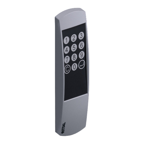
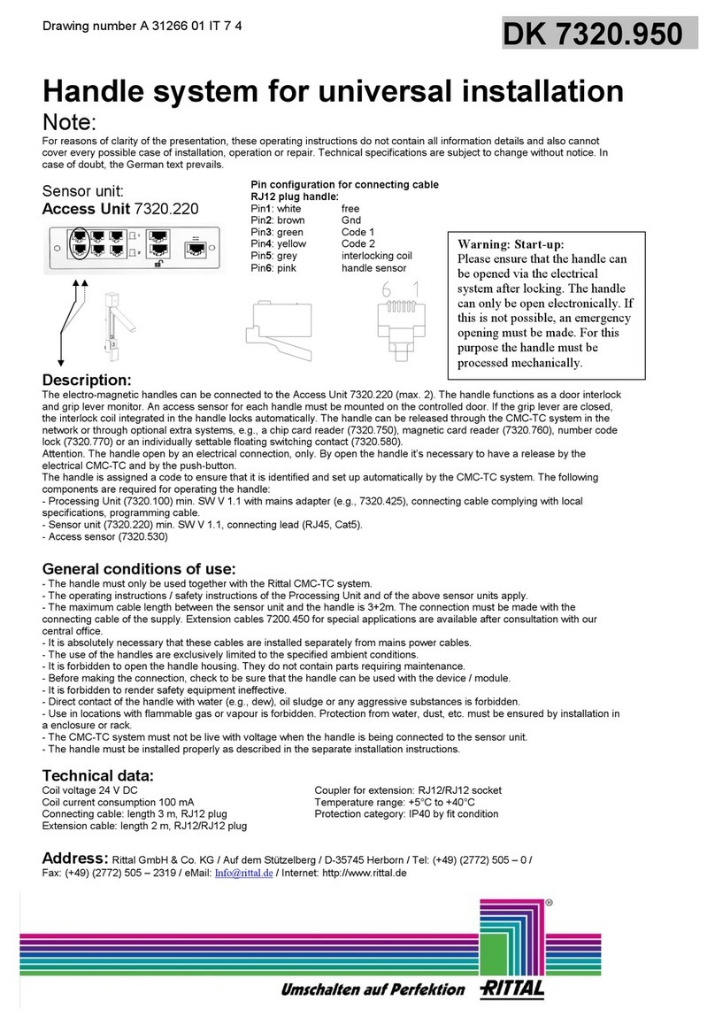
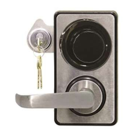
Rittal CMC III User manual

Assembly and operating instructions
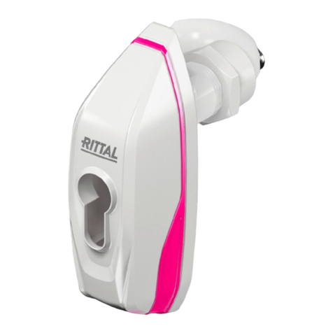
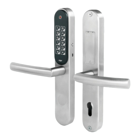
CMC III online comfort handle VX
DK7030.610
DK7030.611

2 Rittal CMC III online comfort handle VX
Foreword
EN Foreword
Dear Customer,
Thank you for choosing our CMC III online comfort
handle VX (referred to hereafter as "comfort handle")!
We wish you every success.
Yours,
Rittal GmbH & Co. KG
Rittal GmbH & Co. KG
Auf dem Stuetzelberg
35745 Herborn
Germany
Tel.: +49(0)2772 505-0
Fax: +49(0)2772 505-2319
E-mail: [email protected]
www.rittal.com
www.rittal.com
www.rittal.de
We are always happy to answer any technical ques-
tions regarding our entire range of products.

Rittal CMC III online comfort handle VX 3
Contents
EN
Contents
1 Notes on documentation......................4
1.1 CE labelling ...................................................... 4
1.2 Storing the documents..................................... 4
1.3 Symbols used in these operating instructions ... 4
1.4 Associated documents..................................... 4
2 Safety instructions................................5
2.1 General safety instructions................................ 5
2.2 Service and technical sta................................ 5
3 Product description..............................6
3.1 Functional description and components ........... 6
3.1.1 Function ........................................................... 6
3.1.2 Components .................................................... 6
3.2 Proper use, foreseeable misuse........................ 6
3.3 Scope of supply ............................................... 6
4 Transport and handling.........................7
4.1 Transport.......................................................... 7
4.2 Unpacking........................................................ 7
5 Installation............................................ 8
5.1 Safety instructions............................................ 8
5.2 Siting location requirements.............................. 8
5.3 Installation of lock insert ................................... 8
5.4 Installation procedure ....................................... 8
5.4.1 Installation notes............................................... 8
5.4.2 Installation on a VX and VX IT sheet steel door . 8
5.4.3 Installation on a VX glazed door........................ 9
5.4.4 Installation on a VX IT glazed door or VX IT
vented door.................................................... 10
5.5 Connecting the comfort handle ...................... 12
5.5.1 Connection to Access Control........................ 12
5.5.2 Connection to external controller .................... 12
6 Operation...........................................13
6.1 Activating the comfort handle ......................... 13
6.2 Operating and display elements...................... 13
6.3 Opening and closing the door ........................ 13
6.4 LED displays .................................................. 13
6.5 Operating the CMC III Processing Unit from
the website..................................................... 13
6.5.1 Monitoring tab ................................................ 13
7 Storage and disposal .........................14
7.1 Storage .......................................................... 14
7.2 Disposal ......................................................... 14
8 Technical specifications......................15
9 Customer service addresses..............16

4 Rittal CMC III online comfort handle VX
1 Notes on documentation
EN 1 Notes on documentation
1.1 CE labelling
Rittal GmbH & Co. KG hereby confirms that the CMCIII
online comfort handle VX is compliant with the EC EMC
Directive 2014/30/EC. An appropriate declaration of
conformity has been prepared. It can be provided on
request.
1.2 Storing the documents
The assembly and operating instructions as well as
all applicable documents are an integral part of the
product. They must be passed to those persons who
are engaged with the unit and must always be avail-
able and on hand for the operating and maintenance
personnel.
1.3 Symbols used in these operating in-
structions
The following symbols are used in this documentation:
Danger!
Hazardous situation leading directly to
death or serious injury if the instruc-
tions are not followed.
Warning!
Hazardous situation which may lead
directly to death or serious injury if the
instructions are not followed.
Caution!
Hazardous situation which may lead to
(minor) injuries if the instructions are
not followed.
Note:
Identification of situations that can lead to
material damage.
◾ This symbol indicates an "action point" and shows
that you should perform an operation or procedure.
1.4 Associated documents
– Installation and Short User Guide
– Assembly and operating instructions for compatible
base systems, e.g. CMC III Processing Unit
Note:
Additional compatible base systems can
be found on the internet at www.rittal.com.
The term "base systems" is used in these
instructions as placeholder for the various
systems.
– CMC III Access Control assembly and operating
instructions

Rittal CMC III online comfort handle VX 5
2 Safety instructions
EN
2 Safety instructions
2.1 General safety instructions
Please observe the subsequent general safety instruc-
tions for the installation and operation of the system:
– Use only original Rittal products or products recom-
mended by Rittal in conjunction with the comfort
handle.
– Please do not make any changes to the comfort
handle that are not described in this manual or in the
associated manuals.
– The operational safety of the comfort handle is only
warranted in case of use as intended and according
to the rules. The technical specifications and limit
values stated must not be exceeded under any cir-
cumstances. In particular, this applies to the specified
ambient temperature range and IP degree of protec-
tion.
– The comfort handle housing must not be opened.
The unit does not contain any parts that need servic-
ing.
– Operating the system in direct contact with water,
aggressive materials or inflammable gases and va-
pours is prohibited.
– Other than these general safety instructions, ensure
you also observe the specific safety instructions
when the tasks described in the following chapters
are performed.
– When closing the handle, take care not to insert your
finger between the handle lever and the comfort han-
dle housing, as it could become trapped.
2.2 Service and technical sta
– The mounting, installation, commissioning, mainte-
nance and repair of this unit may only be performed
by qualified mechanical and electro-technical trained
personnel.
– Only properly instructed personnel may work on a
unit while in operation.

6 Rittal CMC III online comfort handle VX
3 Product description
EN 3 Product description
3.1 Functional description and components
3.1.1 Function
The comfort handle functions as a door latch, handle
lever monitor and visual LED status display. A 40mm
semi-cylinder to DIN 18 252 serves as the master key.
This can be used to open the handle in an emergency.
If the lever handle is closed, the latch mechanism inte-
grated into the comfort handle locks automatically.
The handle can be incorporated into the CMCIII
system. This requires a CMCIII Access Control
(DK7030.202) which is attached near the door in
conjunction with a base system. An example of a
base system might be a CMCIII Processing Unit
(DK7030.000), a CMCIII Processing Unit Compact
(DK7030.010), a Rittal IoT Interface (SK3124.300)
and a Rittal PDU (DK7979.xxx, except PDU basic). In
such cases, the handle can be released via the base
system or using additional optional systems such as a
coded lock (DK7030.222/.223) or transponder reader
(DK7030.232/.233). The comfort handle has an identi-
fier enabling it to be detected automatically by the base
system.
Alternatively, the opening of the comfort handle can
also be controlled via an external controller. In such
cases, the external controller provides both the supply
voltage and the signal for opening the lever handle via
the PLC interface.
Note:
In the following text, the designation
"CMCIII Processing Unit" refers to the
"CMC III Processing Unit" variants and also
to the base systems. All text passages that
apply only to a specific variant are identified
accordingly.
3.1.2 Components
The CMC III online comfort handle VX consists of a
compact plastic housing in RAL 9005 or RAL 7035.
The handle lever, a switch, the master key (profile
half-cylinder) where applicable, and the multi-LED (ring)
are located on the front.
3.2 Proper use, foreseeable misuse
The CMC III online comfort handle VX is only used
for locking the door and monitoring the lever han-
dle. It may only be used in conjunction with a base
system and, where applicable, the Access Control
(DK7030.2020) or alternatively with activation via the
PLC interface. Any other use is not permitted.
The unit is state of the art and built according to rec-
ognised safety regulations. Nevertheless, incorrect use
may result in damage to or faults with the system and
other material assets.
Consequently, the unit must only be used properly
and in a technically sound condition! Any malfunctions
which impair safety should be rectified immediately!
Follow the operating instructions!
The intended use also includes the observance of the
documentation provided and fulfilling the inspection
and maintenance conditions.
Rittal GmbH & Co. KG is not liable for any damage
which may result from failure to comply with the docu-
mentation provided. The same applies to the non-ob-
servance of the valid documentation for any deployed
accessories and the base systems.
Inappropriate use may result in danger. Inappropriate
use includes:
– Use of impermissible tools.
– Improper operation.
– Improper rectification of malfunctions.
– Use of accessories not approved by Rittal GmbH &
Co. KG.
3.3 Scope of supply
– CMC III online comfort handle VX
– Accessories provided (fig.1)
– Installation Guide and Short User Guide
1x
1x M4x12 1x
1x
1x M5x8
1x
1x
M4x16
1x 4x16M4x25
1x
Fig.1: Accessories provided

Rittal CMC III online comfort handle VX 7
4 Transport and handling
EN
4 Transport and handling
4.1 Transport
The unit is delivered in a carton.
4.2 Unpacking
◾ Remove the unit's packaging materials.
Note:
After unpacking, the packaging materials
must be disposed of in an environmentally
friendly way. They consist of the following
materials:
Polyethylene film (PE film), cardboard.
◾ Check the unit for any damage that may have oc-
curred during transport.
Note:
Damage and other faults, e.g. incomplete
delivery, should be reported immediately,
in writing, to the shipping company and to
Rittal.
◾ Remove the unit from the PE film.

8 Rittal CMC III online comfort handle VX
5 Installation
EN 5 Installation
5.1 Safety instructions
◾ Please observe the valid regulations for installation
in the country in which the comfort handle is in-
stalled and operated, and the national regulations for
accident prevention. Please also observe any internal
company regulations, such as work, operating and
safety regulations.
◾ The technical specifications and limit values stated
must not be exceeded under any circumstances. In
particular, this applies to the specified ambient tem-
perature range and IP degree of protection.
◾ If a higher IP protection class is required for a special
application, the transponder reader must be installed
in an appropriate housing or in an appropriate enclo-
sure with the required IP degree of protection.
5.2 Siting location requirements
To ensure the unit functions correctly, the conditions
for the installation site of the unit specified in section8
"Technical specifications" must be observed.
Electromagnetic interference
– Interfering electrical installations (high frequency)
should be avoided.
5.3 Installation of lock insert
A lock insert no. 3524 E or 40 mm profile half-cylinder
to DIN 18 252 may be used in the comfort handle as
an alternative access option for the enclosure. This
allows the handle to be opened manually and inde-
pendently of the electrical activation.
◾ Fit the lock insert or profile half-cylinder in the holder
included with the supply of the comfort handle (fig.2,
MA= 2+1Nm).
M5x8M5x8
Fig.2: Fit the lock insert (left) or profile half-cylinder (right) in
the holder
◾ Then mount the recess with the lock insert or profile
half-cylinder in the comfort handle (fig.3, MA=
2+1Nm).
4x16 4x16
Fig.3: Mount the holder with the lock insert (left) or profile
half-cylinder (right) in the comfort handle
5.4 Installation procedure
There are generally several options for installing the
comfort handle:
– Installation on a VX and VX IT sheet steel door
– Installation on a VX glazed door
– Installation on a VX IT glazed door or VX IT vented
door
5.4.1 Installation notes
◾ Cover the area around where holes are to be drilled
before drilling in order to prevent damage and
scratches.
◾ Connect the connection cables to the comfort handle
so that the connector with the long cables is in the
bottom jack and the connector with the short cables
is in the top jack (see fig.4).
Fig.4: Connecting the cable to the comfort handle
5.4.2 Installation on a VX and VX IT sheet steel
door
The installation is performed directly on the frame of a
VX and VX IT sheet steel door.
◾ Drill suitably sized holes in the required position in the
sheet steel door, depending on the position of the
hinge (fig.5).

Rittal CMC III online comfort handle VX 9
5 Installation
EN
36mm
168mm
36mm
168mm
Ø4.5
Hinge on right Hinge on left
Ø4.5
Fig.5: Drilling the holes
◾ Debur all drilled holes with a 90° countersink.
◾ Remove any swarf from the attachment point of the
comfort handle.
◾ Pass the cable through the opening in the sheet steel
door, depending on the position of the hinge (fig.6).
Hinge on right Hinge on left
Fig.6: Inserting the cable
◾ Attach the handle to the sheet steel door (fig.7).
Hinge on right Hinge on left
Fig.7: Attaching the handle
◾ Push the handle upwards and lock it (fig.8).
Fig.8: Locking the handle (right-hand hinge / left-hand hinge
accordingly)
◾ Screw the comfort handle to the sheet steel door,
depending on the position of the hinge (fig.9 or
fig.10, MA= 1.5±1Nm).
M4x12
MA= 1.5 ±
0.5Nm
Fig.9: Screw-fastening the comfort handle (hinge on right)
M4x12
MA= 1.5 ±
0.5Nm
Fig.10: Screw-fastening the comfort handle (hinge on left)
5.4.3 Installation on a VX glazed door
The installation is performed directly on the frame of a
VX glazed door.
◾ Drill appropriately sized holes in the required position
in the VX glazed door (fig.11).

10 Rittal CMC III online comfort handle VX
5 Installation
EN
17.5mm
182.5mm
17.5mm
182.5mm
Ø4.5
Hinge on right Hinge on left
Ø4.5
Fig.11: Drilling the holes
◾ Debur all drilled holes with a 90° countersink.
◾ Remove any swarf from the attachment point of the
comfort handle.
◾ Pass the cable through the opening in the VX glazed
door, depending on the position of the hinge (fig.12).
Hinge on right Hinge on left
Fig.12: Inserting the cable
◾ Attach the handle to the VX glazed door (fig.13).
Hinge on right Hinge on left
Fig.13: Attaching the handle
◾ Push the handle upwards and lock it (fig.14).
Fig.14: Locking the handle (right-hand hinge / left-hand hinge
accordingly)
◾ Screw the comfort handle to the VX glazed door,
depending on the position of the hinge (fig.15 or
fig.16, MA= 1.5±1Nm).
M4x16
MA= 1.5 ±
0.5Nm
Fig.15: Screw-fastening the comfort handle (hinge on right)
M4x16
MA= 1.5 ±
0.5Nm
Fig.16: Screw-fastening the comfort handle (hinge on left)
5.4.4 Installation on a VX IT glazed door or VX IT
vented door
The installation on the frame of a VX IT glazed door
or VX IT vented door is performed with the provided
compensating panel.

Rittal CMC III online comfort handle VX 11
5 Installation
EN
Hinge on right Hinge on left
Fig.17: Compensating panel
◾ Drill appropriately sized holes in the required position
in the frame of the VX IT glazed door (fig.18).
Hinge on right Hinge on left
20.6mm
156mm
20.6mm
156mm
Ø4.5 Ø4.5
Fig.18: Drilling the holes
◾ Debur all drilled holes with a 90° countersink.
◾ Remove any swarf from the attachment point of the
comfort handle.
◾ Pass the cable through the opening in the designer
compensating panel depending on the door hinge
(fig.19)
Hinge on right Hinge on left
Fig.19: Inserting the cable
◾ Attach the handle to the designer compensating
panel (fig.20).
Hinge on right Hinge on left
Fig.20: Attaching the handle to the designer compensating
panel
◾ Push the handle upwards and lock it (fig.21).
Fig.21: Locking the handle (right-hand hinge / left-hand hinge
accordingly)
◾ Screw the designer compensating panel including
comfort handle to the VX IT glazed door, depending
on the position of the hinge (fig.22 or fig.23, MA=
1.5±1Nm).

12 Rittal CMC III online comfort handle VX
5 Installation
EN
M4x25
MA= 1.5 ±
0.5Nm
ISO7380
Fig.22: Screw-fastening the designer compensating panel
including comfort handle (hinge on right)
M4x25
MA= 1.5 ±
0.5Nm
ISO7380
Fig.23: Screw-fastening the designer compensating panel
including comfort handle (hinge on left)
5.5 Connecting the comfort handle
5.5.1 Connection to Access Control
The Access Control supplies the comfort handle with
the necessary operating voltage via the connection
cable. A separate power supply unit does not need to
be connected.
◾ First disconnect the CAN bus from the Access Con-
trol.
◾ Fit the handle to the door to be monitored (see sec-
tion5.4 "Installation procedure").
◾ Connect the handle via the connection cable to the
Access Control.
◾ Connect a reader unit to the Access Control with the
connection cable.
◾ Connect the CAN bus to the Access Control again.
5.5.2 Connection to external controller
Opening the comfort handle may alternatively be con-
trolled without an Access Control, connected coded
lock or transponder reader. In such cases, the required
voltage supply and the signal for opening the handle
lever must be provided by the external controller via the
PLC interface.
◾ For this purpose, please note the pin assignment of
the RJ12 connector on the comfort handle connec-
tion cable.
P
in 1
P
in 6
P
in 6
P
in 1
Fig.24: Connection pins on the RJ12 connector
Pin 1: +24V (supply voltage)
Pin 2: GND
Pin 3: RS485A
Pin 4: RS485B
Pin 5: Control signal for door latch (input)
Pin 6: Acknowledgement from handle lever (signal
output)
◾ Please also note the following:
– Pins 3 and 4 are not used for activation via the PLC
interface.
– The 24V DC control signal is needed to activate
and open the handle lever.
– The feedback signal "Gnd" on pin 6 means that
the handle lever is closed. The maximum current
capacity is 100mA.

Rittal CMC III online comfort handle VX 13
6 Operation
EN
6 Operation
6.1 Activating the comfort handle
After connecting the comfort handle to the Access
Control or external controller with the connection cable,
the comfort handle is automatically active (see sec-
tion5.5 "Connecting the comfort handle"). Separate
activation is not required.
6.2 Operating and display elements
42
1
3
Fig.25: Front of the comfort handle
Legend
1 Handle lever
2 Switch
3 Master key (profile half-cylinder)
4 Multi-LED (ring)
6.3 Opening and closing the door
Opening the door and comfort handle
◾ Once enabled: Press the switch on the front of the
handle to open the handle lever.
The door can then be swung open.
Closing the door and comfort handle
◾ Close the door completely.
◾ Press the handle lever fully downwards until it latches
home.
6.4 LED displays
A multi-LED for the status display is integrated at the
front of the comfort handle (fig.25, item4). "Access"
mode is activated as standard for the multi-LED.
Colour Status
Blue (continu-
ous light)
Handle lever and door closed.
Green (contin-
uous light)
Handle lever enabled.
Yellow (contin-
uous light)
Handle lever and/or door open.
Tab. 1: Multi-LED displays
6.5 Operating the CMC III Processing Unit
from the website
After logging on to the CMC III Processing Unit, the
web interface for operating the device is displayed.
6.5.1 Monitoring tab
The description of the comfort handle is added and the
current status of the comfort handle can be viewed in
the Monitoring tab.
Note:
As the comfort handle does not have a
separate entry in the left tree structure, all
information on this point can be found in the
CMC III Access Control operating instruc-
tions (DK7030.202).

14 Rittal CMC III online comfort handle VX
7 Storage and disposal
EN 7 Storage and disposal
7.1 Storage
If the device is not used for a long period, Rittal recom-
mends that it be disconnected from the mains power
supply and protected from damp and dust.
7.2 Disposal
Since the comfort handle consists mainly of the
"housing" and "circuit board" parts, the device must be
passed on to the electronic waste recycling system for
disposal.

Rittal CMC III online comfort handle VX 15
8 Technical specifications
EN
8 Technical specifications
Technical specifications CMC III online comfort handle VX
Model no. DK7030.610/DK7030.611
W x H x D (mm) 41 x 386 x 42, door-mounted
Rated voltage 24 V DC
Rated current max. 100 mA
Operating temperature range +5°C…+55°C
Operating humidity range 5%…70% relative humidity, non-condensing
Protection category IP30 to IEC 60 529
Connection cable 2.9m with RJ12 connector
Operation/signals 1 x Multi-LED
Tab. 2: Technical specifications

16 Rittal CMC III online comfort handle VX
9 Customer service addresses
EN 9 Customer service addresses
For technical queries, please contact:
Tel.: +49(0)2772 505-9052
E-mail: [email protected]
Homepage: www.rittal.com
For complaints or service requests, please contact:
Tel.: +49(0)2772 505-1855
E-mail: [email protected]

Rittal CMC III online comfort handle VX 17
Notes
EN

18 Rittal CMC III online comfort handle VX
Notes
EN

Rittal CMC III online comfort handle VX 19
Notes
EN

◾ Enclosures
◾ Power Distribution
◾ Climate Control
◾ IT Infrastructure
◾ Software & Services
RITTAL GmbH & Co. KG
Auf dem Stuetzelberg · 35745 Herborn · Germany
Phone +49 2772 505-0
www.rittal.com/contact
You can find the contact details of all
Rittal companies throughout the world here.
10.2021/D-0000-00002249-00-EN
Other manuals for CMC III
9
This manual suits for next models
2
Table of contents
Other Rittal Lock manuals
Popular Lock manuals by other brands

Targus
Targus DEFCON CL user guide

Cal-Royal
Cal-Royal SDLP-RND-ADA installation manual
OPERTIS
OPERTIS eLOCK ES7670 operating instructions
DynaLock
DynaLock 3000LC Series installation instructions
Schlage
Schlage Touchscreen Deadbolt with Alarm user guide
AmazonBasics
AmazonBasics Travel Sentry AB-TL100 quick start guide
