Riva RC2103HD-6611 User manual

RC210309-2014-A
1
Quick Start Guide
This manual provides the instructions on the quick installation and the basic configuration commonly for an IP
camera with a regular fisheye lens and with a panomorph lens.
1. Connect cables to IP device
Connect required cables to the device including the power cable, LAN cable, and other optional cables.
To see the correct positions of all connectors, refer to the following image below.
The device is polarity sensitive. Incorrect power connection
may cause malfunction or damage to the IP device.
Caution
!
Power Adaptor Connector
(DC 12V)
LAN Connector
Reset Button
microSD/SDHC Slot
Power Adaptor Connector
(Located under the plate)
PAL/NTSC Button
Terminal Connector
* The model design is subject to change without any prior notice.

RC210309-2014-A
2
Caution
!
2. Install IP device
There are only two mounting types explained in this manual. Refer to the device’s installation guide for more
various mounting types.
Semi-Flush Mount
1) Place the installation template included in
the package on the desired installation surface.
2) Drill holes on the correct spots based on the
template paper, and insert the anchor blocks
into the holes.
3) Open the dome cover.
*Refer to the caution below for the details about
how to open the cover.
4) Connect necessary cables including a LAN
cable and a power cable to the camera.
5) Hold the camera against the surface where
the camera will be mounted by matching the
alignment holes with the corresponding anchor
blocks.
6) Route the cables through the cable hole at
the bottom of the camera, and tighten the
anchor blocks with the screws.
7) Attach the dome cover on the main body,
and lock it up by rotating the dome cover.
*Refer to the caution below for the details of how to
attach the dome cover.
When placing the dome cover, look for the carved triangle mark on both dome cover
and main body. Both triangles should be aligned together when placing the cover. Once
the cover has been placed, rotate the dome cover clockwise for a secure lock. To
detach the cover, rotate the cover counterclockwise. Then, align the two triangle marks
each other, and pull the cover.
To prevent products from damage, place the camera on a stable and non-vibrating
surface. If the stability is in doubt, consult safety personnel for reinforcements, and
then proceed with the installation.
Caution
!

RC210309-2014-A
3
Caution
!
Flush Mount
1) Place the installation template included in the
package on the desired installation surface.
2) Drill holes on the correct spots based on the
template paper, and insert the anchor blocks
into the holes.
3) Open the dome cover.
*Refer to the caution below for the details about
how to open the cover.
4) Connect necessary cables including a LAN
cable and a power cable to the camera.
5) Unscrew the three bolts attached on the
dome cover’s surface, and place the FMB
mount between the dome shell and the bottom
circular cylinder. Then, align the three screw
holes on each component together, and tighten
the three components with the bolts included in
the package.
6) Attach the three components-combined
dome cover to the main body, and lock it up by
rotating the cover.
*Refer to the caution below for the details about
how to lock the cover.
7) Tighten the camera’s body into the mounting
surface’s anchor blocks by inserting the screws
included in the package through the screw
holes around the edge of the FMB mount.
When placing the dome cover, look for the carved triangle mark on both dome cover
and main body. Both triangles should be aligned together when placing the cover. Once
the cover has been placed, rotate the dome cover clockwise for a secure lock. To
detach the cover, rotate the cover counterclockwise. Then, align the two triangle marks
each other, and pull the cover.
To prevent products from damage, place the camera on stable and non-vibrating
surfaces. If the stability is in doubt, consult safety personnel for reinforcements, and
then proceed with the installation.
Caution
!
circular cylinder
FMB mount
dome shell

RC210309-2014-A
4
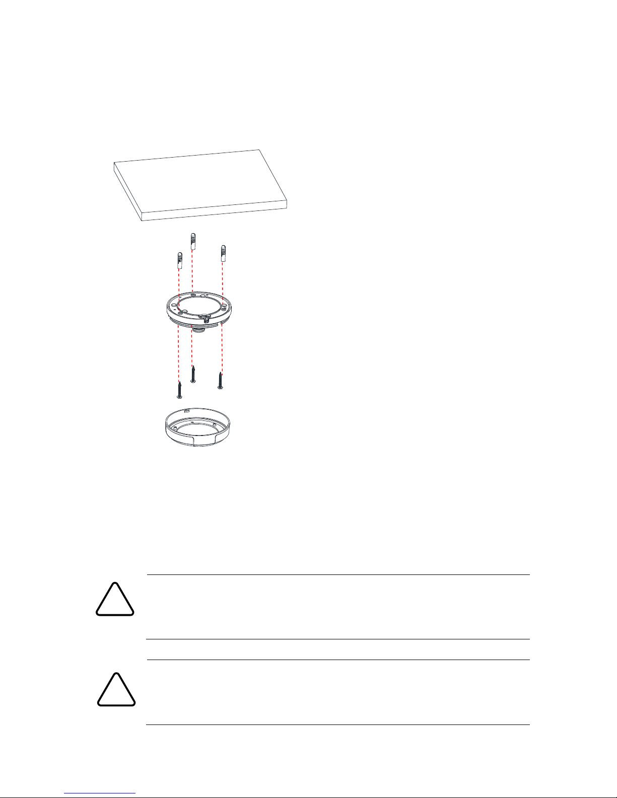
3. Set up network environment
The default IP address of the device is 192.168.XXX.XXX. Users can identify the IP address of the device from
converting the MAC address’s hexadecimal numbers, which is attached to the device. Be sure that the device
and PC are on a same area network before running the installation.
Generic IP Environment
In case of generic private network environment where IP address 192.168.XXX.XXX are used, users may view
the live streaming images on a web page using the device’s default IP address:
1. Convert the device’s MAC address to the IP address. Refer to the Hexadecimal-Decimal Conversion Chart
at the end of the manual.
(The MAC address of the device is attached on the side or bottom of the device.)
2. Start the Microsoft® Internet Explorer web browser and enter the IP address of the device.
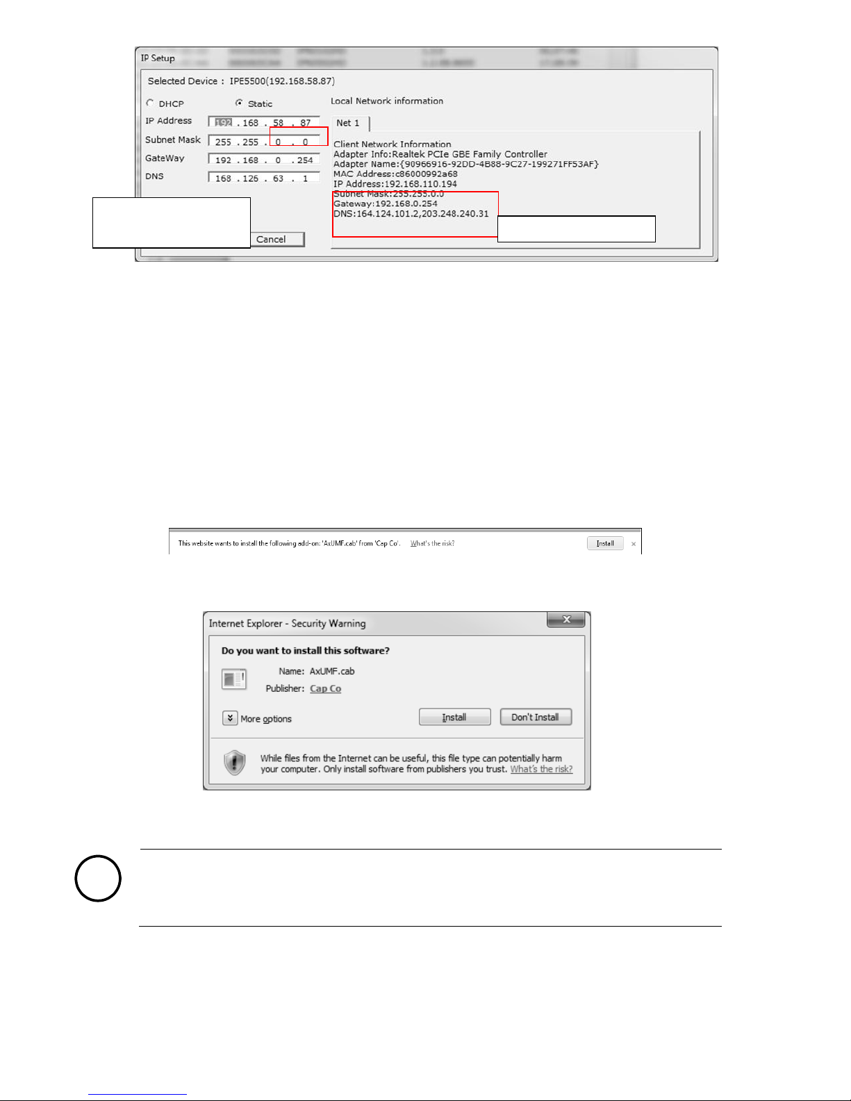
3. Web streaming and device configurations are supported through ActiveX program. When the ActiveX
installation pop-up window appears, authorize and install the ActiveX setup.exe.
Custom IP Environment
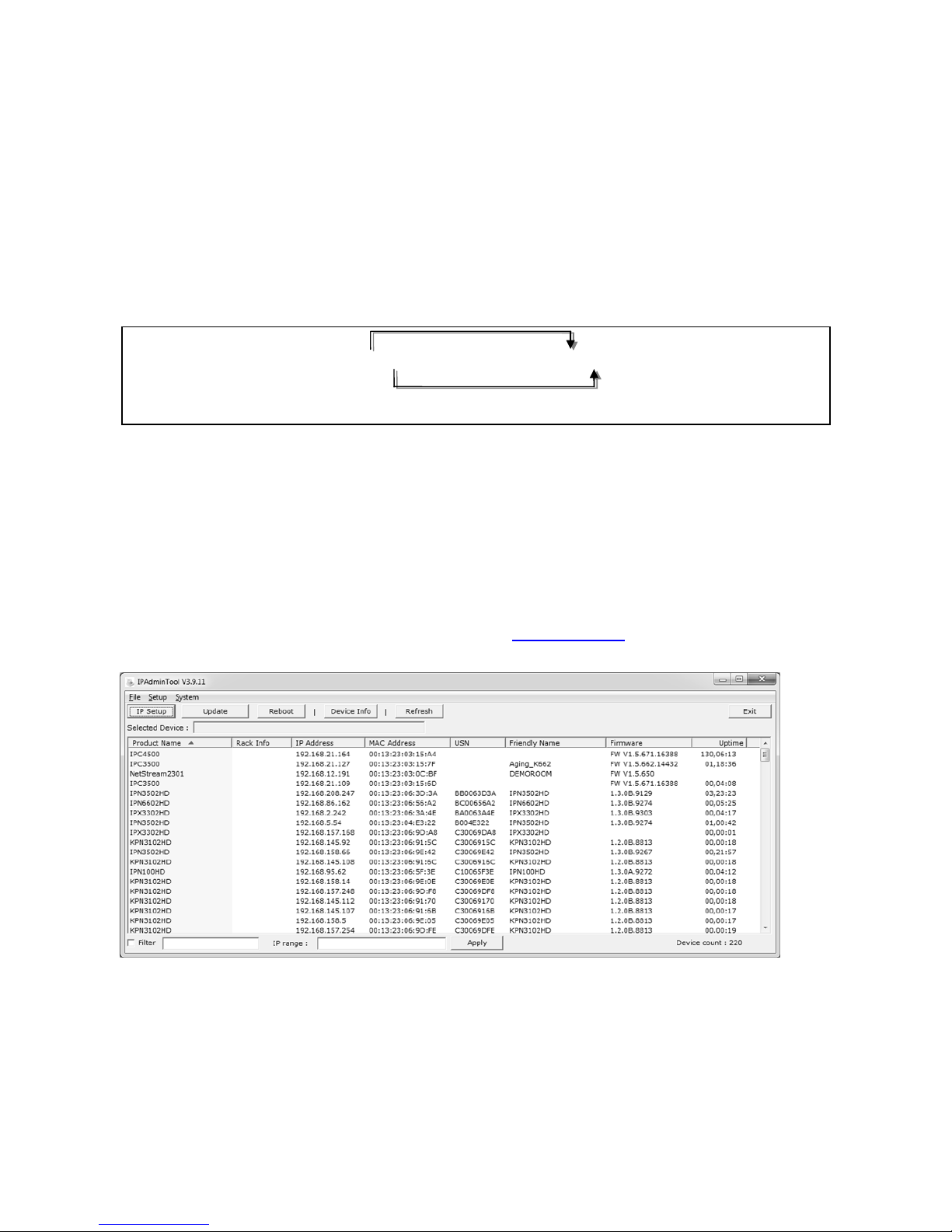
IPAdminTool is a management tool, which automatically scans all of the network products for users to perform
administrative tasks, which includes network configurations, firmware update, device reboot, and device
organizations. IPAdminTool and the manual can download from www.rivatech.de homepage.
To modify the device’s default IP address for customized network area;
1. Find the device from the IPAdminTool’s list and highlight the device’s name.
2. Right-click the mouse and select IP Address; IP Setup window appears.
MAC address = 00-13-23-01-14-B1 → IP address = 192.168.20.177
Convert the last two sets of hexadecimal numbers to decimal numbers.

RC210309-2014-A
5
3. In the IP Setup’s window, information under Local Network information displays the user/PC’s network
area information. Those information need to be incorporated to the IP Address, Subnet Mask, Gateway,
and DNS boxes, except the last 2 sets of IP Address, which are to be the unique numbers for the device.
Refer to the image above for the setting
4. Click Setup to complete the modification.
4. View video on web page
Installation of ActiveX control
Once the device’s proper IP address has been identified, type the URL in a web browser to access the camera.
At first time access, installation window may pop up.
1. When the browser asks to install the AxUMF software, click Install to proceed.
2. When Setup installation pop-up window appears, click Install to proceed with rest of installations.
Note
i
Depending on system OS and Internet Explorer version, installation experience may differ from
one another. Figures described above are from Windows 7, Internet Explorer 9 environment.
PC environment Info
Give new unique IP address in
last two sets and mirror other
information in other boxes

RC210309-2014-A
6
Login to webpage
To set up the Network configuration:
1. Click Setup on the upper right of the web page. The login page is displayed as below.
2. Enter the default user name (root) and password (pass), and then select OK.
3. Under the setup page, click Basic Configuration menu, and then select TCP/IP from the submenu
4. Select “Use the following IP address”configuration, and type the proper IP address to use, and then click
the Apply button on the bottom of the page.
When modifying the IP address, be advised to have the correct Subnet mask and Gateway ready.
More Information
To learn more about using other features of your devices, refer to the manuals as “RIVA Web Interface Manual
Full HD Series” or “VCAsys User Manual (Online Help)”, which is available on www.rivatech.de homepage.
5. Reboot
Perform the following procedures to reset your device:
1. Press the reset button for 2 seconds while the device is in use.
2. Wait for the system to reboot.
Caution
!
Please do not hold the reset button for more than 2 seconds. Otherwise, the
camera may be switched to its Factory Default settings.
6. Factory Default
Resetting the device back to the factory default will initialize all parameters including the IP address back to
the factory defaults. To reset back to the factory default:
1. Press the reset button and hold it while the device is in use.
2. Release the button after 10 seconds.
3. Wait for the system to reboot.
The default username
and password are:
root and pass.

RC210309-2014-A
7
Note
i
The factory default settings can be inferred as follows:
IP address: 192.168.xx.yy
Network mask: 255.255.0.0
Gateway: 192.168.0.1
User ID: root
Password: pass
7. Safe Mode
Your device will get restarted with safe mode when the device does not completely boot certain times.
The errors are mainly caused by these two factors: power source unplugged or damage occurred on
firmware file during the system boot.
The messages like below will appear on the webpage when your device has been rebooted in ‘safe mode’.
Then, you should follow the instructions on the webpage according to the steps in a row.
Note
i
There is another method to update firmware, which is using IPAdminTool.
Please refer to ‘IPAdminTool User’s Manual.pdf’for the detailed procedure.
Note
i
If your device is still at safe mode after trying to update firmware, please contact
your local agency to get further assistance.

RC210309-2014-A
8
Hexadecimal-Decimal Conversion Table
Refer to the following table when converting the MAC address of your device to IP address.
Hex
Dec
Hex
Dec
Hex
Dec
Hex
Dec
Hex
Dec
Hex
Dec
Hex
Dec
0
0
25
37
4A
74
6F
111
94
148
B9
185
DE
222
1
1
26
38
4B
75
70
112
95
149
BA
186
DF
223
2
2
27
39
4C
76
71
113
96
150
BB
187
E0
224
3
3
28
40
4D
77
72
114
97
151
BC
188
E1
225
4
4
29
41
4E
78
73
115
98
152
BD
189
E2
226
5
5
2A
42
4F
79
74
116
99
153
BE
190
E3
227
6
6
2B
43
50
80
75
117
9A
154
BF
191
E4
228
7
7
2C
44
51
81
76
118
9B
155
C0
192
E5
229
8
8
2D
45
52
82
77
119
9C
156
C1
193
E6
230
9
9
2E
46
53
83
78
120
9D
157
C2
194
E7
231
0A
10
2F
47
54
84
79
121
9E
158
C3
195
E8
232
0B
11
30
48
55
85
7A
122
9F
159
C4
196
E9
233
0C
12
31
49
56
86
7B
123
A0
160
C5
197
EA
234
0D
13
32
50
57
87
7C
124
A1
161
C6
198
EB
235
0E
14
33
51
58
88
7D
125
A2
162
C7
199
EC
236
0F
15
34
52
59
89
7E
126
A3
163
C8
200
ED
237
10
16
35
53
5A
90
7F
127
A4
164
C9
201
EE
238
11
17
36
54
5B
91
80
128
A5
165
CA
202
EF
239
12
18
37
55
5C
92
81
129
A6
166
CB
203
F0
240
13
19
38
56
5D
93
82
130
A7
167
CC
204
F1
241
14
20
39
57
5E
94
83
131
A8
168
CD
205
F2
242
15
21
3A
58
5F
95
84
132
A9
169
CE
206
F3
243
16
22
3B
59
60
96
85
133
AA
170
CF
207
F4
244
17
23
3C
60
61
97
86
134
AB
171
D0
208
F5
245
18
24
3D
61
62
98
87
135
AC
172
D1
209
F6
246
19
25
3E
62
63
99
88
136
AD
173
D2
210
F7
247
1A
26
3F
63
64
100
89
137
AE
174
D3
211
F8
248
1B
27
40
64
65
101
8A
138
AF
175
D4
212
F9
249
1C
28
41
65
66
102
8B
139
B0
176
D5
213
FA
250
1D
29
42
66
67
103
8C
140
B1
177
D6
214
FB
251
1E
30
43
67
68
104
8D
141
B2
178
D7
215
FC
252
1F
31
44
68
69
105
8E
142
B3
179
D8
216
FD
253
20
32
45
69
6A
106
8F
143
B4
180
D9
217
FE
254
21
33
46
70
6B
107
90
144
B5
181
DA
218
FF
255
22
34
47
71
6C
108
91
145
B6
182
DB
219
23
35
48
72
6D
109
92
146
B7
183
DC
220
24
36
49
73
6E
110
93
147
B8
184
DD
221
Other manuals for RC2103HD-6611
1
Table of contents
Other Riva IP Camera manuals

Riva
Riva RC6702HD-6311 User manual

Riva
Riva RC1100M User manual

Riva
Riva RTC1130 User manual

Riva
Riva RC2102HD-5511 User manual

Riva
Riva RC1202HD-5241 User manual

Riva
Riva RTC series User manual

Riva
Riva RC6802HD-6211 User manual

Riva
Riva RC1202HD User manual

Riva
Riva RC2102HD-5511 User manual

Riva
Riva RC2103HD-6611 User manual