Rixen TK-6200 User manual

CONTENTS
■TK-6200 specifications---------------------------------1
■Instrument descriptions--------------------------------2
■Display descriptions------------------------------------3
■Key descriptions----------------------------------------4
■Instructions---------------------------------------------5
■RS-232 transfer protocol-------------------------------8
■Precautions--------------------------------------------11

■TK-6200 specifications
Measuring Range (ITS-90)
- 200.00 ~ + 1370.0 ℃, (-328.00 ~ +2498.0 ℉)
Accuracy (at 23±3℃)
±0 .05% of rdg + 0 .1℃,other ±0 .1% of rdg + 0 .2℃
Resolution
0.01℃(under 999.99℃),0.1℃(above 1000.0℃)
0.01℉(under 999.99℉) ,0.1℉(above 1000.0℉)
Sampling rate
Approx 0 . 5 sec
Main Functions
Hi/Lo Alarm setting,T1-T2, data hold, Max./Min./Avg
values record, switchable ℃/℉, digital USB / RS-232
output, switchable AC/DC, Battery sign and low battery
warning, calibration, LED Back-light luminescence, IP66
water proof, dust proof.
Signal Output
0 .0 1℃/ 1 BIT, RS-232, USB(protocol provided)
Power source
9 V Battery or AC Adapter
Dimensions/Weight
150 x 75 x 28 mm,Approx. 320g ( battery included)
Input connection
Mini connector waterproof socket(IP66)
Standard Applications
TK-6200 High accuracy thermometer(Type K)
TU-655C Plastic Carry case
TU-609 Battery 9V006P
Instruction manual and warranty
Operating environment
-20 ~ + 60℃; 0 ~ 100 %RH
Certifications
CE, RoHS, IP-66
Accessories
Temperature probe
Please find the LP series for your reference (customized)
TU-RS232-C
specified RS232 cable and WINDOWS software
TU-USB-C
specified RS232 cable and WINDOWS software
※Above accuracy and sampling rate excludes errors generated by Temperature probe.
※Specifications are subject to change without notice.
-1-
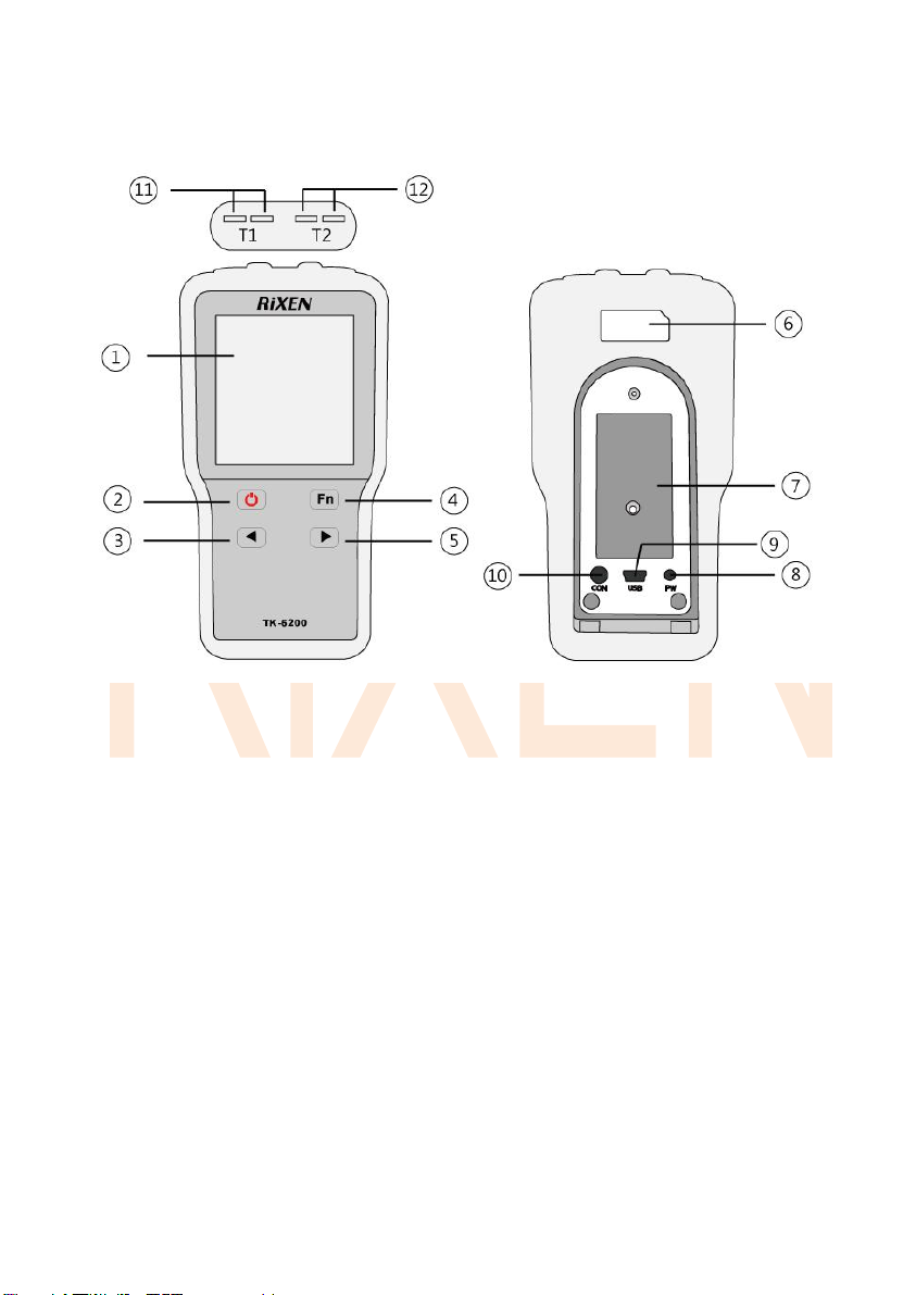
■Instrument descriptions
○
1Multi-Function LCD Display
○
7Battery cover
○
2Power switch
○
8AC Adaptor Input
○
3Setting and℃/℉switching
○
9USB Output port
○
4Function key
○
10 RS-232 Output connector
○
5Setting
○
11 T1 Probe input connector
○
6Model No. and Serial No.
○
12 T2 Probe input connector
-2-

■Display descriptions
Abnormal displays
A. When Area A shows, please let go off all keys.
B. When Area A shows, the situations below may be the causes:
1. Temp. over 1370.0℃(2498.0℉)or under -200.00℃(-328.00℉)
2. The Temp. probe is broke or not inserted.
3. When showing the T1 - T2 real temp. display either one testing probe is Abnormal.
4. If is appears when turning on the instrument¸please let go off all keys and tune
Instrument on again.
-3-
Display
Descriptions
Battery Power Symbol
Manual shut down
LED Back light on
Buzzer on
CAL
Under Calibrating
MAX
Maximum Value
HOLD
Data Hold
MIN
Minimum Value
AVG
Average Value
T1
T1 probe
T2
T2 probe
Hi.A
High Alarm
Lo.A
Low Alarm
Area Digit A.B.C.
Testing Value, Alarm setting Value, T1,T2 indicating
℃/℉
℃:Celsius units ,℉: Fahrenheit units

■Key descriptions
※The ℃/℉ is changeable only under the testing mode.
Key
Function
Descriptions
LCD display
Power
On/Off
Press once for power on or off. (If the instrument is
left without any button operation, it will automatically turn
off after five minutes.)
+
Manual
turn off
Hold key, then hold key to turn on,
entering the manual turn off mode. When appears,
please let this two keys release.
(2s)
Baud
Rate,
Hi/Lo
Alarm,
Ref.,
Span
Hold
mode
Under testing mode, press to enter the reading
HOLD mode. Use and to change display
functions. Press to leave.
HOLD
AVG MAX
MIN
Setting
Mode
Under testing mode, press for over 2 sec. until the
area B shows to enter the setting mode. Push
key and key to change the baud rate, after data
confirmed; please press for over 2 seconds again. for
enter the next level. Push key to increase the value.
Push key to reduce the value. Push key to
change digit. Determine the value re-hold key for
over 2 seconds, into the next level, who wish to skip the
other settings, hold down key will be automatically
set to the last, the complete contents of each set will be
automatically saved, and return to the testing mode.
Hi.A
Lo.A
(2s)
Left Key
Under any mode press key to change data.
--
Under testing mode, hold key for over 2 seconds to
change℃/℉. After changed please let go.
℃℉
Right Key
Under any mode press key to change data.
--
+
Back
Light on
Under any mode, press and key the back light
will be turned on. Note: When the battery power is under
25%,the LED back light will not be able to function.
Alarm On
(2s)
Under any mode, press and key after 2
seconds the buzzer will be turned on. The mark
appeared.
-4-

■Instructions
A. Testing Mode:
Press and to switch display conditions.
Normal conditions
Probe condition, warning data condition, Power indication
T1 Real-time
Temperature display
T1 Temp. data, (Area A)
T1 Hi.A data (Area B), T1 Lo.A data(Area C)
T2 Real-time
Temperature display
T2 Temp. data, (Area A)
T2 Hi.A data (Area B), T2 Lo.A data (Area C)
T1-T2 Real-time
Temperature display
T1 - T2 Temp. data(Area A)
T1 data (Area B), T2 data, (Area C)
※Warning alert
When the temperature is higher than the HI.A, the HI.A symbol will flash.
When the temperature is lower than the Lo.A, the Lo.A symbol will flash
The buzzer will make the warning sound if is turned on.
※Please let go off all keys, while waiting for the reading test mode and setting
mode to return to the testing mode.
-5-
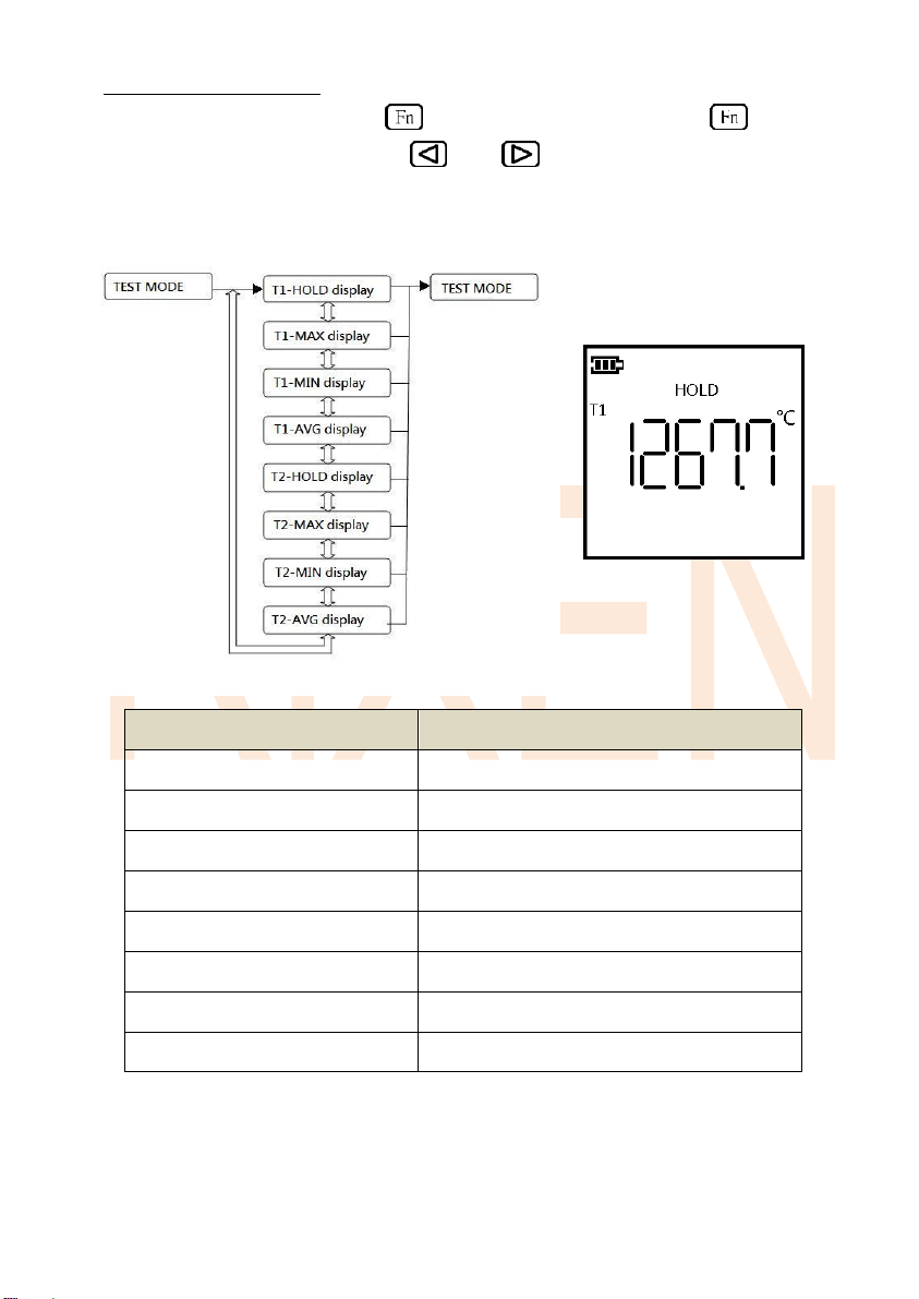
B. Readings hold mode
Under the testing mode, press to enter hold mode, and press to
return to the testing mode. Press and key to switch the display
condition.
The data will be deleted when the mode or system are changed.
Condition
Display content
T1-HOLD display
Lock the T1 Temperature data
T1-MAX display
T1 Maximum Temperature data
T1-MIN display
T1 Minimum Temperature data
T1-AVG display
T1 Average Temperature data
T2-HOLD display
Lock the T2 Temperature data
T2-MAX display
T2 Maximum Temperature data
T2-MIN display
T2 Minimum Temperature data
T2-AVG display
T2 Average Temperature data
-6-

C. Setting Mode
Under the testing mode press for over 2 seconds to enter the setting mode.
Press for over 2 seconds to switch to the next setting mode.
Push key to increase the value, Push key to reduce the value
Push key to change digit
When all settings are done it will return to the testing mode.
※The initial setting of baud rate is 4800.
Limitation Range Settings:
Alarm settings highest value: + 1370.0℃(+2498.0℉)
Alarm settings Lowest value: - 200.0℃ (- 328.0℉)
Deviation setting range: ± 100.00℃ Start with 0.00℃; (± 180.00℉ Start with 0.00℉)
Span setting range: 0.00% ~ 200.00% starts with 100.00%
-7-
Display content
Description
baud display
Baud Rate data options
T1 - Hi.A display
T1 Temp. high point alert settings
T1 - Lo.A display
T1 Temp. low point alert settings
T2 - Hi.A display
T2 Temp. high point alert settings
T2 - Lo.A display
T2 Temp. low point alert settings
T1 - rEF display
T1 Temp. low point ref settings
T1–SPAn display
T1 Temp. high point span settings
T2 - rEF display
T2 Temp. low point ref settings
T2 - SPAn display
T2 Temp. high point span settings

■RS-232 transfer protocol
RS-232 The transmission end is one way transfer via the three wire
(touch ground) to input and output.
Using the original transmission line or cable under 10m is recommended.
Baud rate: 57600, 19200, 9600, 4800
Transfer status: / 8 / N / 1
Transfer content: (8BIT)
Read Holding Registers by Function 03H
A. Request Data Frame
Ex: Read the data from address 0x0000 (Read 4-byte of data from address 0x0000)
Slave
address
Function
Starting
address
Hi
Starting
address
Lo
No. of
Byte
Hi
No. of
Byte
Hi
CRC
Lo
CRC
Hi
02H
03H
00H
00H
00H
04H
44H
3AH
Response Data Frame
Ex Response value=4-Byte Response Data= ”80003”
Slave
address
Function
Byte
count
Data
Hi
Data
Middle
Data
Lo
Data
Last
CRC
Lo
CRC
Hi
02H
03H
04H
00H
01H
38H
83H
CAH
92H
0x00013883=80003,Real value = 80003/100,Real value =800.03
B. Request Data Frame
Ex: Read the data from address 0x0000 (Read 8-byte of data from address 0x0000)
Slave
address
Function
Starting
address
Hi
Starting
address
Lo
No. of
Byte
Hi
No. of
Byte
Hi
CRC
Lo
CRC
Hi
02H
03H
00H
00H
00H
08H
44H
3FH
Response Data Frame
Ex Response value= 8-Byte Response Data =”80003”and”81067”
-8-

Slave
address
Function
Byte
count
Data(1)
Hi
Data(1)
Middle
Data(1)
Lo
Data (1)
Last
02H
03H
08H
00H
01H
38H
83H
0x00013883=80003,Real value = 80003/100,Real value = 800.03
0x00013CAB=81067,Real value = 81067/100,Real value = 810.67
☆℃ and ℉ set is data of MOD “bit 05” at address 0x000A
C .Request Data Frame
Ex: Read the data from address 0x0008 (Read 10-byte of data from address 0x0008)
Slave
address
Function
Starting
address
Hi
Starting
address
Lo
No. of
Byte
Hi
No. of
Byte
Hi
CRC
Lo
CRC
Hi
02H
03H
00H
08H
00H
0AH
44H
3CH
Response Data Frame,Ex Response value= 10-Byte
Slave
address
Function
Byte
count
Data(1)
Hi
Data(1)
Middle
Data(1)
Lo
Data (1)
Last
02H
03H
0AH
03H
E8H
FCH
18H
Data (1) Hi and Data (1) Middle is value of T1-Hi.A=0x03E8=1000
Data (1) Lo and Data (1) Last is value of T1-Lo.A=0xFc18=-1000
Data (2) Hi and Data (2) Middle is value of T2-Hi.A=0x0BB8=3000
Data (2) Lo and Data (2) Last is value of T2-Lo.A=0x07D0=2000
Data (3) Hi and Data (3) Lo is value of MOD=0x0002
Bit 15~bit 6 no use
1. bit 05 is ℉/℃ >>> 0=℃
>>> 1=℉
2. bit 04 no use
3. bit 03 is T2-Error >>> 1= T2 ERROR
4. bit 02 is T1-Error >>> 1= T1 ERROR
5. bit 01~bit 00 is Power >>> 2=Power 74~50%
-9-
Data(2)
Hi
Data (2)
Middle
Data(2)
Lo
Data (2)
Last
CRC
Lo
CRC
Hi
00H
01H
3CH
ABH
CAH
4AH
Data(2)
Hi
Data (2)
Middle
Data(2)
Lo
Data (2)
Last
Data(3)
Hi
Data(3)
Lo
CRC
Lo
CRC
Hi
0BH
B8H
07H
D0H
00H
02H
C8H
42H
**Example**
Set mode:
1. Temperature unit=℃
2. No use
3.T1 no ERROR
4. T2 no ERROR
5. Power74~50%
Set mode MOD
Bit 15
Bit 14
Bit 13
Bit 12
Bit 11
Bit 10
Bit 09
Bit 08
X
X
X
X
X
X
X
X
Bit 07
Bit 06
Bit 05
Bit 04
Bit 03
Bit 02
Bit 01~ Bit 00
X
X
℉=1/℃=0
X
T2 Error=1
T1 Error=1
Power
☆Power Meter is divided into 4 parts 11=100~75% 10=74~50%
01=49~25% 00=24~0%
-10-
Address
Data name
Data size
0000h
T1 Real-Time Data(Hold)
4-Byte
0001h
T1 Max
4-Byte
0002h
T1 Min
4-Byte
0003h
T1 Avg
4-Byte
0004h
T2 Real-Time Data(Hold)
4-Byte
0005h
T2 Max
4-Byte
0006h
T2 Min
4-Byte
0007h
T2 Avg
4-Byte
0008h
First 2-byte = T1-Hi.A
Last 2-byte = T1-Lo.A
4-Byte
0009h
First 2-byte = T2-Hi.A
Last 2-byte = T2-Lo.A
4-Byte
000Ah
Set mode = MOD
2-Byte
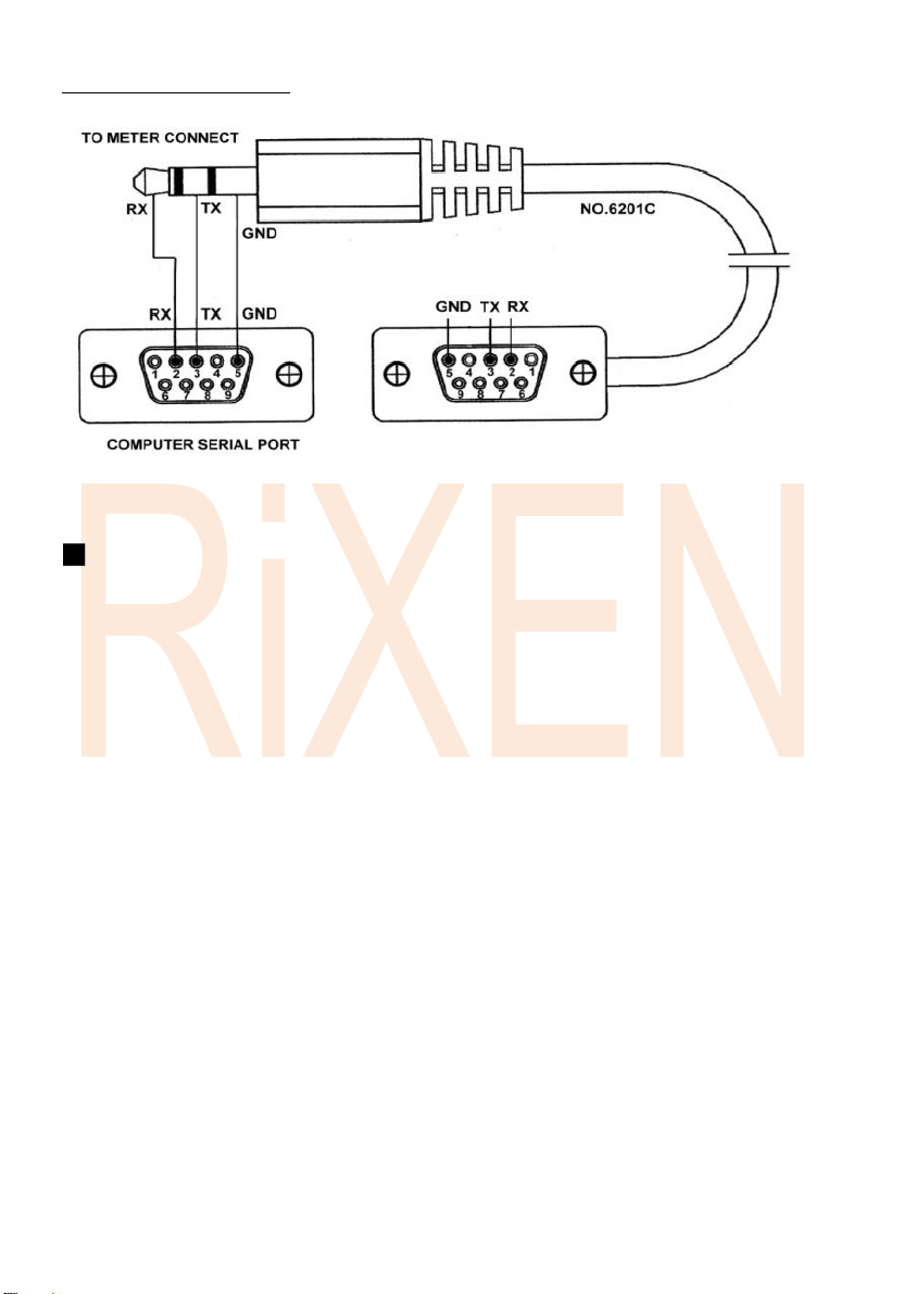
D. RS-232 connecting cable
Precautions
1. This instrument has a waterproof function, please do not use it in a high temperature
environment or with corrosive materials to avoid leakage or damage.
2. To avoid the problems that might occur when connecting to the computer, the Rixen USB
computer interface cable and windows software (Model No. TU-USB-C) is recommended.
3. Please keep the temperature stabled when measuring the temperature of an object to
obtain a more accurate result.
4. When the instrument shows power shortage warning, please immediately replace the
batteries to avoid incorrect readings.
5. When the instrument is not in use for a long time, please put the instrument and all
Accessories in the protective case, and kept it in a clean and dry environment, and Please
avoid direct sunlight
6. If there are any operation questions or malfunction, please contact your local distributor
or our service department.
-11-
Table of contents
Other Rixen Thermometer manuals


