Digital Controller
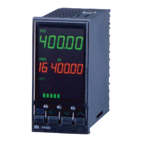
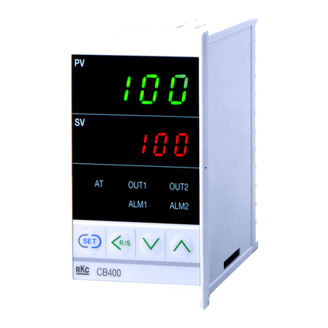
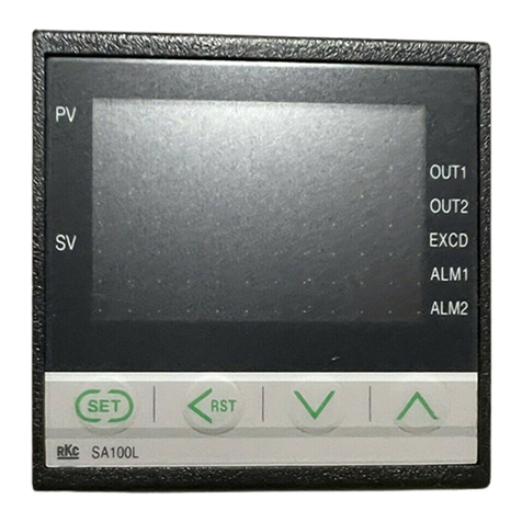
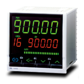
REX-C100/C400/C410/C700/C900
INSTRUCTION MANUAL
IMNZC22-E1
Th nk you for purch sing this RKC product. In order to chieve m ximum perform nce
nd ensure proper oper tion of your new instrument, c refully re d ll the instructions
in this m nu l. Ple se pl ce the m nu l in convenient loc tion for e sy reference.
To prevent injury to persons, d m ge to instrument nd equipment,
suit ble extern l protection device sh ll be required.
All wiring must be completed before power is turned on to prevent
electric shock, fire or d m ge to instrument nd equipment.
This instrument must be used in ccord nce with the specific tions
to prevent fire or d m ge to instrument nd equipment.
This instrument is not intended for use in loc tions subject to
fl mm ble or explosive g ses.
Do not touch high-volt ge connections such s power supply
termin ls, etc. to void electric shock.
RKC is not responsible if this instrument is rep ired, modified or
dis ssembled by other th n f ctory- pproved personnel.
M lfunction c n occur nd w rr nty is void under these conditions.
This product is intended for use with industri l m chines, test nd
me suring equipment. (It is not designed for use with medic l
equipment nd nucle r energy.)
This is Cl ss A instrument. In domestic environment, this instrument
m y c use r dio interference, in which c se the user m y be required to
t ke ddition l me sures.
This instrument is protected from electric shock by reinforced insul tion.
Provide reinforced insul tion between the wire for the input sign l nd
the wires for instrument power supply, source of power nd lo ds.
Be sure to provide n ppropri te surge control circuit respectively for
the following:
- If input/output or sign l lines within the building re longer th n 30 meters.
- If input/output or sign l lines le ve the building, reg rdless the length.
This instrument is designed for inst ll tion in n enclosed instrument tion
p nel. All high-volt ge connections such s power supply termin ls must
be enclosed in the instrument tion p nel to void electric shock by
oper ting personnel.
All prec utions described in this m nu l should be t ken to void
d m ge to the instrument or equipment.
All wiring must be in ccord nce with loc l codes nd regul tions.
All wiring must be completed before power is turned on to prevent
electric shock, instrument f ilure, or incorrect ction. The power must be
turned off before rep iring work for input bre k nd output f ilure
including repl cement of sensor, cont ctor or SSR, nd ll wiring must
be completed before power is turned on g in.
To prevent instrument d m ge s result of f ilure, protect the power line nd
the input/output lines from high currents with suit ble overcurrent protection
device with dequ te bre king c p city such s fuse, circuit bre ker, etc.
Prevent met l fr gments or le d wire scr ps from f lling inside
instrument c se to void electric shock, fire or m lfunction.
Tighten e ch termin l screw to the specified torque found in the m nu l
to void electric shock, fire or m lfunction.
For proper oper tion of this instrument, provide dequ te ventil tion for
he t dispens tion.
Do not connect wires to unused termin ls s this will interfere with
proper oper tion of the instrument.
Turn off the power supply before cle ning the instrument.
Do not use vol tile solvent such s p int thinner to cle n the
instrument. Deform tion or discolor tion will occur. Use soft, dry cloth
to remove st ins from the instrument.
To void d m ge to instrument displ y, do not rub with n br sive
m teri l or push front p nel with h rd object.
When high l rm with hold ction is used for Al rm function, l rm does
not turn on while hold ction is in oper tion. T ke me sures to prevent
overhe ting which m y occur if the control device f ils.
NOTICE
This m nu l ssumes th t the re der h s fund ment l knowledge of
the principles of electricity, process control, computer technology nd
communic tions.
The figures, di gr ms nd numeric v lues used in this m nu l re only
for purpose of illustr tion.
RKC is not responsible for ny d m ge or injury th t is c used s
result of using this instrument, instrument f ilure or indirect d m ge.
RKC is not responsible for ny d m ge nd/or injury resulting from the
use of instruments m de by imit ting this instrument.
Periodic m inten nce is required for s fe nd proper oper tion of this
instrument. Some components h ve limited service life, or
ch r cteristics th t ch nge over time.
Every effort h s been m de to ensure ccur cy of ll inform tion
cont ined herein. RKC m kes no w rr nty expressed or implied, with
respect to the ccur cy of the inform tion. The inform tion in this
m nu l is subject to ch nge without prior notice.
No portion of this document m y be reprinted, modified, copied,
tr nsmitted, digitized, stored, processed or retrieved through ny
mech nic l, electronic, optic l or other me ns without prior written
pprov l from RKC.
1. PRODUCT CHECK
1) Control action
F: PID ction with utotuning (Reverse ction)
D: PID ction with utotuning (Direct ction)
W: He t/Cool PID ction with utotuning (W ter cooling)
1
A : He t/Cool PID ction with utotuning (Air cooling)
1
2) Input type
,
3) Range code
Refer to “9. INPUT RANGE TABLE.”
4) First control output [OUT1] Heat-side)
M: Rel y cont ct G: Trigger for tri c driving
2
V: Volt ge pulse 8: Current (4 to 20 mA DC)
5)
Second control output [OUT2] Cool-side)
3
No symbol: When control ction is F or D. M: Rel y cont ct
V: Volt ge pulse 8: Current (4 to 20 mA DC)
6)
Alarm 1 [ALM1],
7) Alarm 2 [ALM2]
N: No l rm H: Process high l rm
A: Devi tion high l rm J: Process low l rm
B: Devi tion low l rm K: Process high l rm with hold ction
C: Devi tion high/low l rm L: Process low l rm with hold ction
D: B nd l rm P: He ter bre k l rm (HBA)[CTL-6]
4
E: Devi tion high l rm S: He ter bre k l rm (HBA)[CTL-12]
4
with hold ction R: Control loop bre k l rm (LBA)
5
F: Devi tion low l rm
with hold ction
G: Devi tion high/low l rm with hold ction
1
C100 c nnot be specified in He t/Cool PID ction.
2
For the C100, when control output is trigger output for tri c driving, only the
ALM1 is v il ble.
3
For the C100, there is no second control output.
4
He ter bre k l rm (HBA) c nnot be specified in c se of ALM1. Also, it isn’t
possible to specify when control output is current output.
5
As control loop bre k l rm (LBA), only either the ALM1 or ALM2 is selected.
Check th t power supply volt ge is lso the s me s th t specified
when ordering.
2. MOUNTING
2.1 Mounting Cautions
(1) This instrument is intended to be used under the following environment l
conditions. IEC61010-1)
[OVERVOLTAGE CATEGORY II, POLLUTION DEGREE 2]
(2) Use this instrument within the following environment conditions:
Allow ble mbient temper ture: 0 to 50 C
Allow ble mbient humidity: 45 to 85 % RH
Inst ll tion environment conditions: Indoor use, Altitude up to 2000 m
(3) Avoid the following conditions when selecting the mounting loc tion:
R pid ch nges in mbient temper ture which m y c use condens tion.
Corrosive or infl mm ble g ses.
Direct vibr tion or shock to the m infr me.
W ter, oil, chemic ls, v por or ste m spl shes.
Excessive dust, s lt or iron p rticles.
Excessive induction noise, st tic electricity, m gnetic fields or noise.
Direct ir flow from n ir conditioner.
Exposure to direct sunlight.
Excessive he t ccumul tion.
(4) Mount this instrument in the p nel considering the following conditions:
Provide dequ te ventil tion sp ce so th t he t does not build up.
Do not mount this instrument directly bove equipment th t gener tes
l rge mount of he t (he ters, tr nsformers, semi-conductor function l
devices, l rge-w tt ge resistors.)
If the mbient temper ture rises bove 50 C, cool this instrument with
forced ir f n, cooler, etc. Cooled ir should not blow directly on this
instrument.
In order to improve s fety nd the immunity to withst nd noise, mount
this instrument s f r w y s possible from high volt ge equipment,
power lines, nd rot ting m chinery.
High volt ge equipment: Do not mount within the s me p nel.
Power lines: Sep r te t le st 200 mm.
Rot ting m chinery: Sep r te s f r s possible.
For correct functioning mount this instrument in horizont l position.
(5) In c se this instrument is connected to supply by me ns of perm nent
connection, switch or circuit-bre ker sh ll be included in the inst ll tion.
This sh ll be in close proximity to the equipment nd within e sy re ch of
the oper tor. It sh ll be m rked s the disconnecting device for the
equipment.
Mounting brackets C100/400/410/700/900): 2
Instruction manual IMNZC22-E1): 1
<Accessories>
CAUTION
C100
-
(1)(2) (3) (4) (6)(7)
C400
C410
C700
C900
-
(1) (2) (3) (4)(5) (6)(7)
**
WARNING
!


