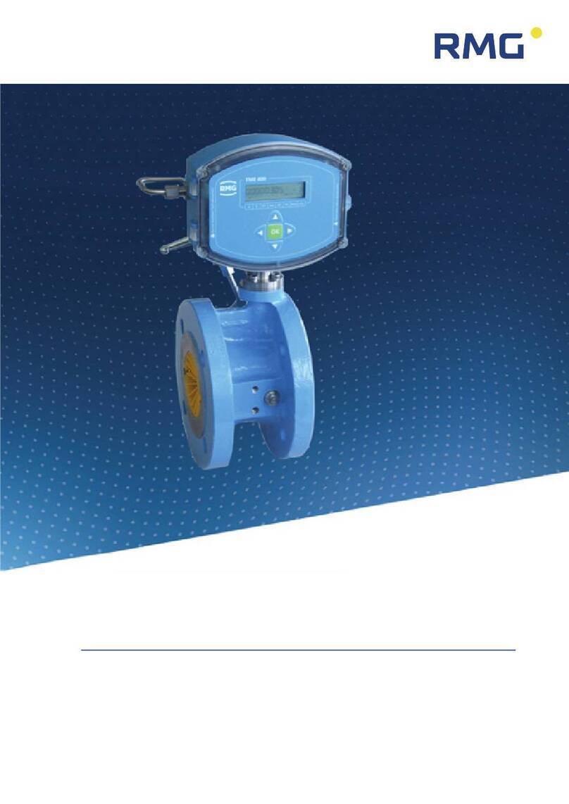
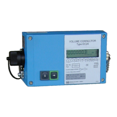
RMG EC 900 User manual

5HOLDEOH0HDVXUHPHQWRI*DV
&RPSDFW*DV9ROXPH&RUUHFWRU(&
23(5$7,1*,16758&7,216
6WDWXV 1RYHPEHUQG
9HUVLRQ D

.........................................................................................................................................................................................................
.
.........................................................................................................................................................................................................
.
0DQXDO(&ā(1Dā1RYHPEHUQG
0DQXIDFWXUHU 2XUFXVWRPHUVHUYLFHLVDYDLODEOHIRUWHFKQLFDOTXHULHV
$GGUHVV 50*0HVVWHFKQLN*PE+
2WWR+DKQ6WUDH
'%XW]EDFK
7HOHIRQVZLWFKERDUG
±
7HOHIRQVHUYLFH
±
7HOHIRQVSDUHSDUWV
±
)D[
±
(PDLO VHUYLFH
#
UP
J
FRP
2ULJLQDO'RFXPHQW 7KH(&BPDQXDOBHQBDIURP1RYHPEHUQG
IRU&RPSDFW*DV9ROXPH&RUUHFWRU(&LVWKHGRF
XPHQWWUDQVODWHGILUVWIURPWKH*HUPDQRULJLQDOYHUVLRQ
$Q\KRZWKLVGRFXPHQWPD\VHUYHDVUHIHUHQFHIRU
WUDQVODWLRQVLQWRRWKHUODQJXDJHV3OHDVHXVHLQFDVHRI
DQ
\
XQFHUWDLQWLHVWKH*HUPDQYHUVLRQDVPDLQUHIHUHQFH
1RWH 8QIRUWXQDWHO\SDSHULVQRWXSGDWHGDXWRPDWLFDOO\
ZKHUHDVWHFKQLFDOGHYHORSPHQWFRQWLQXRXVO\DGYDQFHV
7KHUHIRUHZHUHVHUYHWKHULJKWWRPDNHWHFKQLFDO
FKDQJHVLQUHJDUGWRWKHUHSUHVHQWDWLRQVDQGVSHFLILFD
WLRQVRIWKHVHRSHUDWLQJLQVWUXFWLRQV7KHODWHVWYHUVLRQ
RIWKLVPDQXDODQGRWKHUGHYLFHVFDQEHGRZQORDGHGDW
\RXUFRQYHQLHQFHIURPRXU,QWHUQHWKRPHSDJH
ZZZUP
J
FRP
'DWHFUHDWHG 0D
\
VWUHYLVLRQGDWH -XO
\
«
WKUHYLVLRQGDWH -XQH
WKDXSGDWHGDWH 1RYHPEHUQG
'RFXPHQWYHUVLRQDQGODQ
J
XD
J
H
'RFXPHQWYHU
VLRQ
(&BPDQXDOBHQBD
1RYHPEHUQG
/DQ
J
XD
J
H (1
1RWLFH
7KHPDQXDOLVYDOLGIRUYHUVLRQRIWKHKDUGZDUHGHYHORSPHQWVLQFH+RZHYHU
ROGHUKDUGZDUHYHUVLRQVDUHDOVRGHVFULEHGLQWKLVPDQXDO

CONTENTS
.........................................................................................................................................................................................................
.
.........................................................................................................................................................................................................
.
0DQXDO(&ā(1Dā1RYHPEHUQG
INTRODUCTION................................................................................... 1
Description and variants.......................................................................................1
New symbols as per EN 12405 ............................................................................3
CONSTRUCTION AND FUNCTION ......................................................4
Gas volume corrector ...........................................................................................4
Casing and control panel............................................................................................... 4
Electronic components.................................................................................................. 5
Ex zone 1 ................................................................................................................................................... 5
Calculation of the volume at base conditions ................................................................ 9
Totalizers....................................................................................................................... 9
Overview .................................................................................................................................................... 9
Disturbance totalizers.............................................................................................................................. 10
Time system ................................................................................................................ 10
General .................................................................................................................................................... 10
Rules for changing time ........................................................................................................................... 10
PTB telephone time service ..................................................................................................................... 10
Operating parameters for controlling time and date................................................................................ 10
Data protection ........................................................................................................... 11
Data logger..........................................................................................................12
Maximum values (maximum load) ............................................................................... 12
Archives and logbooks ................................................................................................ 13
Archive structure ..................................................................................................................................... 13
Periodic archive ....................................................................................................................................... 13
Disturbance archive................................................................................................................................. 14
Daily archive ............................................................................................................................................ 14
Monthly archive ....................................................................................................................................... 15
Legal metrological logbook as per PTB-A 50.7 ........................................................................................ 15
Parameter change logbook...................................................................................................................... 16
Event logbook .......................................................................................................................................... 16
Event archive ........................................................................................................................................... 17
Load archive ............................................................................................................................................ 17
Communication...................................................................................................18
Interfaces .................................................................................................................... 18
Optical interface as per IEC 62056-21 on the front panel ....................................................................... 18
Electrical interface ................................................................................................................................... 18
Modems ...................................................................................................................... 18
Transmission protocols ............................................................................................... 19
M900 protocol ......................................................................................................................................... 19
DSfG-B protocol....................................................................................................................................... 19
Modbus protocol...................................................................................................................................... 19
Communication unit (CU) ............................................................................................ 19
SAFETY INSTRUCTIONS.....................................................................20
Instructions for the installer...............................................................................21
Marking ....................................................................................................................... 21
Use.............................................................................................................................. 21
Installation and commissioning in areas subject to explosion hazards ........................ 21
Commissioning............................................................................................................ 22

CONTENTS
.........................................................................................................................................................................................................
.
.........................................................................................................................................................................................................
.
0DQXDO(&ā(1Dā1RYHPEHUQG
Servicing, maintenance and troubleshooting............................................................... 22
Changing the battery................................................................................................... 22
Removal ...................................................................................................................... 22
Special condition for EC 921 / EC 922 ....................................................................... 23
Connection value limits for EC 921 / EC 922.............................................................. 23
INSTALLATION ..................................................................................26
Connecting the pressure transmitter.................................................................26
Three-way check valve ................................................................................................ 26
Electrical connections ........................................................................................27
Devices for Ex zone 1 (EC 911 and EC 912) ................................................................ 27
Devices for Ex zone 2 (EC 921 and EC 922) ................................................................ 28
Pin assignments - modem/Ethernet............................................................................ 29
Pin assignments of the serial interface........................................................................ 29
Connection of an external CU 900 communication module......................................... 30
Requirements for the protection class IP65 ................................................................ 31
Example of connection ................................................................................................ 31
COMMISSIONING..............................................................................32
Configuring the interface....................................................................................32
EC 911 and EC 912..................................................................................................... 32
EC 921 and EC 922..................................................................................................... 33
Defining codes ....................................................................................................34
Setting the contrast............................................................................................34
OPERATION .......................................................................................35
How to operate the EC 900 ................................................................................35
Structural design......................................................................................................... 35
Keys.....................................................................................................................37
Accessing device data ........................................................................................38
Data categories ........................................................................................................... 38
Codes.......................................................................................................................... 38
Calibration switch........................................................................................................ 39
Preconditions for important operations....................................................................... 40
Setting totalizers...................................................................................................................................... 40
Resetting totalizers .................................................................................................................................. 40
Resetting archives ................................................................................................................................... 40
Resetting logbooks .................................................................................................................................. 40
Changing the U1 code (Proceed in the same way to change the U2 code.) ........................................... 40
Changing the C1 code (Proceed in the same way to change the C2 and C3 codes.) ............................. 40
Changing parameters..........................................................................................41
Examples of programming..................................................................................41
Inputting a code .......................................................................................................... 42
Displaying and changing parameters for calculating the K coefficient......................... 43
Displaying and changing pressure parameters ............................................................ 45

CONTENTS
.........................................................................................................................................................................................................
.
.........................................................................................................................................................................................................
.
0DQXDO(&ā(1Dā1RYHPEHUQG
Adjusting interface parameters ................................................................................... 48
Changing the pulse value of the gas meter.................................................................. 49
Setting or resetting totalizers ...................................................................................... 50
Device data ................................................................................................................. 51
Deleting an event ........................................................................................................ 52
On-the-fly calibration................................................................................................... 53
Viewing archive entries (example: periodic archive) .................................................... 54
Viewing maximum load values ...........................................................................56
Description.................................................................................................................. 56
Maximum load display................................................................................................. 57
Current supply quantity within the current gas day ..................................................... 57
Monitoring the supply period....................................................................................... 58
Archive displays .......................................................................................................... 58
List of parameters and operating modes...........................................................59
Screen: CUSTOMIZED DISPLAY............................................................................................................... 59
Screen: Extended customized display...................................................................................................... 60
Screen: 1.0.0.0 (Digital inputs) ................................................................................................................ 60
Screen: 1.0.1.0 (Counter for incoming pulses) ........................................................................................ 60
Screen: 1.0.2.0 (Use of the digital inputs) ............................................................................................... 61
Screen: 1.0.3.0 (Selection of sensor type and filter for the digital inputs) .............................................. 61
Screen: TOT ............................................................................................................................................. 62
Screen: 1.1.0.0 (totalizer functions) ........................................................................................................ 62
Screen: 1.1.1.0 (on-the-fly calibration) .................................................................................................... 62
Screen: 1.1.2.0 (setting totalizers) .......................................................................................................... 62
Screen: 1.1.3.0 (totalizer mode) .............................................................................................................. 63
Screen: 1.1.4.0 (load limits)..................................................................................................................... 63
Screen: PTZ.............................................................................................................................................. 64
Screen: 2.1.0.0 (pressure) ....................................................................................................................... 64
Screen: 2.1.1.0 (pressure values displayed) ............................................................................................ 64
Screen: 2.1.2.0 (pressure limits) ............................................................................................................. 64
Screen: 2.1.3.0 (pressure default) ........................................................................................................... 64
Screen: 2.1.4.0 (pressure parameters).................................................................................................... 65
Screen: 2.1.5.0 (pressure modes) ........................................................................................................... 65
Screen: 2.2.0.0 (temperature) ................................................................................................................. 65
Screen: 2.2.1.0 (temperature values displayed) ...................................................................................... 65
Screen: 2.2.2.0 (temperature limits)........................................................................................................ 66
Screen: 2.2.3.0 (temperature default) ..................................................................................................... 66
Screen: 2.2.4.0 (temperature parameters) .............................................................................................. 66
Screen: 2.2.5.0 (temperature modes)...................................................................................................... 66
Screen: 2.3.0.0 (compressibility factor)................................................................................................... 66
Screen: 2.3.1.0 (values displayed for the compressibility factor)............................................................ 67
Screen: 2.3.2.0 (K coefficient default) ..................................................................................................... 67
Screen: 2.3.3.0 (fixed values for the gas quality)..................................................................................... 67
Screen: 2.3.4.0 (base conditions)............................................................................................................ 67
Screen: 2.4.0.0 (components for K coefficient calculation using AGA 8-92DC) ...................................... 68
Screen: 2.4.1.0 (CO2source) .................................................................................................................. 68
Screen: OPER........................................................................................................................................... 69
Screen: 3.2.0.0 (date and time)............................................................................................................... 69
Screen: 3.2.1.0 (time values)................................................................................................................... 69
Screen: 3.2.2.0 (time parameters)........................................................................................................... 70
Screen: 3.3.0.0 (battery).......................................................................................................................... 70
Screen: 3.4.0.0 (time synchronization).................................................................................................... 70
Screen: 3.5.0.0 (customized display)....................................................................................................... 71
Screen: 3.6.0.0 (symbols)........................................................................................................................ 71
Screen: 3.7.0.0 (language)....................................................................................................................... 71
Screen: 3.8.0.0 (power supply)................................................................................................................ 72

CONTENTS
.........................................................................................................................................................................................................
.
.........................................................................................................................................................................................................
.
0DQXDO(&ā(1Dā1RYHPEHUQG
Screen: TARIFF ........................................................................................................................................ 73
Screen: 4.1.0.0 (archives)........................................................................................................................ 73
Screen: 4.1.1.0 (periodic archive)............................................................................................................ 73
Screen: 4.1.1.1 (periodic archive - entries).............................................................................................. 74
Screen: 4.1.2.0 (daily archive) ................................................................................................................. 75
Screen: 4.1.2.1 (daily archive - entries) ................................................................................................... 75
Screen: 4.1.3.0 (monthly archive)............................................................................................................ 77
Screen: 4.1.3.1 (monthly archive - entries).............................................................................................. 77
Screen: 4.1.4.0 (disturbance archive)...................................................................................................... 79
Screen: 4.1.4.1 (disturbance archive - entries)........................................................................................ 79
Screen: 4.1.5.0 (event archive)................................................................................................................ 79
Screen: 4.1.5.1 (event archive - entries).................................................................................................. 80
Screen: 4.1.6.0 (load archive).................................................................................................................. 80
Screen: 4.1.6.1 (load archive - entries).................................................................................................... 81
Screen: 4.2.0.0 (logbooks)....................................................................................................................... 82
Screen: 4.2.1.0 (legal metrological logbook) ........................................................................................... 82
Screen: 4.2.1.1 (legal metrological logbook - entries) ............................................................................. 82
Screen: 4.2.2.0 (parameter logbook)....................................................................................................... 83
Screen: 4.2.2.1 (parameter logbook - entries)......................................................................................... 83
Screen: 4.2.3.0 (event logbook)............................................................................................................... 84
Screen: 4.2.3.1 (event logbook - entries)................................................................................................. 84
Screen: 4.3.0.0 (archive parameters) ...................................................................................................... 84
Screen: 4.4.0.0 (archive modes).............................................................................................................. 85
Screen: 4.5.0.0 (logbook modes)............................................................................................................. 85
Screen: 4.6.0.0 (maximum load test)....................................................................................................... 85
Screen: FLOW .......................................................................................................................................... 87
Screen: 5.1.0.0 (flow rate)....................................................................................................................... 87
Screen: 5.1.1.0 (measured values for the flow rate)................................................................................ 87
Screen: 5.1.2.0 (flow rate limits) ............................................................................................................. 87
Screen: 5.1.3.0 (flow rate parameters).................................................................................................... 88
Screen: 5.1.4.0 (flow rate modes) ........................................................................................................... 88
Screen: TYPE............................................................................................................................................ 90
Screen: 6.1.0.0 (type of pressure transmitter) ........................................................................................ 90
Screen: 6.2.0.0 (type of temperature transmitter)................................................................................... 90
Screen: 6.3.0.0 (type of the volume meter)............................................................................................. 91
Screen: 6.4.0.0 (device data)................................................................................................................... 91
Screen: 6.5.0.0 (checksum)..................................................................................................................... 92
Screen: 6.6.0.0 (customer data).............................................................................................................. 92
Screen: 6.7.0.0 (RMG data) ..................................................................................................................... 93
Screen: COMM......................................................................................................................................... 93
Screen: 7.1.0.0 (optical interface) ........................................................................................................... 94
Screen: 7.2.0.0 (COM1 interface)............................................................................................................ 94
Screen: 7.3.0.0 (Com filters) ................................................................................................................... 95
Screen: 7.4.0.0 (Status display of important CU parameters)................................................................. 95
Screen: 7.5.0.0 (Com test) ...................................................................................................................... 97
Screen: OUTPUTS .................................................................................................................................... 98
Screen: 8.1.0.0 (digital outputs) .............................................................................................................. 98
Screen: 8.1.1.0 (digital output 1)............................................................................................................. 98
Screen: 8.1.1.1 (digital output 1 – display values)................................................................................... 98
Screen: 8.1.1.2 (digital output 1 – parameters)....................................................................................... 99
Screen: 8.1.2.0 (digital output 2)............................................................................................................. 99
Screen: 8.1.2.1 (digital output 2 – display values)................................................................................. 100
Screen: 8.1.2.2 (digital output 2 – parameters)..................................................................................... 100
Screen: 8.1.3.0 (digital output 3)........................................................................................................... 100
Screen: 8.1.3.1 (digital output 3 – display values)................................................................................. 100
Screen: 8.1.3.2 (digital output 3 – parameters)..................................................................................... 101
Screen: 8.1.4.0 (digital output 4)........................................................................................................... 101
Screen: 8.1.4.1 (digital output 4 – display values)................................................................................. 101
Screen: 8.1.4.2 (digital output 4 – parameters)..................................................................................... 101
Screen: 8.1.5.0 (digital output 5)........................................................................................................... 102
Screen: 8.1.5.1 (digital output 5 – display values)................................................................................. 102
Screen: 8.1.5.2 (digital output 5 – parameters)..................................................................................... 102

CONTENTS
.........................................................................................................................................................................................................
.
.........................................................................................................................................................................................................
.
0DQXDO(&ā(1Dā1RYHPEHUQG
Screen: 8.1.6.0 (digital output 6)........................................................................................................... 102
Screen: 8.1.6.1 (digital output 6 – display values)................................................................................. 102
Screen: 8.1.6.2 (digital output 6 – parameters)..................................................................................... 103
Screen: 8.2.0.0 (analogue outputs) ....................................................................................................... 103
Screen: 8.2.1.0 (analogue output 1) ...................................................................................................... 103
Screen: 8.2.1.1 (analogue output 1 - display values)............................................................................. 103
Screen: 8.2.1.2 (analogue output 1 - parameters)................................................................................. 104
Screen: 8.2.2.0 (analogue output 2) ...................................................................................................... 104
Screen: 8.2.2.1 (analogue output 2 - display values)............................................................................. 104
Screen: 8.2.2.2 (analogue output 2 - parameters)................................................................................. 104
Screen: 8.2.3.0 (analogue output 3) ...................................................................................................... 105
Screen: 8.2.3.1 (analogue output 3 - display values)............................................................................. 105
Screen: 8.2.3.2 (analogue output 3 - parameters)................................................................................. 105
Screen: 8.2.4.0 (analogue output 4) ...................................................................................................... 105
Screen: 8.2.4.1 (analogue output 4 - display values)............................................................................. 105
Screen: 8.2.4.2 (analogue output 4 - parameters)................................................................................. 106
Screen: CU............................................................................................................................................. 106
Screen: 9.1.0.0 (communication parameters) ....................................................................................... 106
Screen: 9.1.1.0 (modem: GSM / GPRS / ISDN).................................................................................... 106
Screen: 9.1.1.1 (parameters for radio module GSM)............................................................................. 107
Screen: 9.1.1.2 (parameters for GPRS modem)..................................................................................... 107
Screen: 9.1.1.2.1 (TCP lists) .................................................................................................................. 107
Screen: 9.1.1.3 (parameters modem interface, protocols).................................................................... 108
Screen: 9.1.1.4 (service programs)........................................................................................................ 108
Screen: 9.1.2.0 (USB: internal in EC 900 / external in CU 900)............................................................ 108
Screen: 9.1.3.0 (serial: DB9 on the right side of EC 900 case).............................................................. 109
Screen: 9.1.4.0 (plug: interface on internal multi-pin connector for service)......................................... 109
Screen: 9.1.5.0 (TCP/IP: ethernet)........................................................................................................ 109
Screen: 9.2.0.0 (time parameters)......................................................................................................... 110
Screen: 9.2.1.0 (time server parameters).............................................................................................. 110
Screen: 9.3.0.0 (DSfG parameters)........................................................................................................ 110
Screen: 9.3.1.0 (EADRs) ........................................................................................................................ 111
Screen: 9.3.2.0 (dial numbers) .............................................................................................................. 111
Screen: 9.3.3.0 (archive names)............................................................................................................ 111
Screen: 9.3.4.0 (ada identification) ....................................................................................................... 112
Screen: 9.4.0.0 (system)........................................................................................................................ 112
Screen: 9.4.1.0 (ISB).............................................................................................................................. 112
Screen: 9.6.0.0 (service programs)........................................................................................................ 112
Fault messages ................................................................................................ 113
Alarms....................................................................................................................... 113
Warnings ................................................................................................................... 114
MAINTENANCE................................................................................115
Changing the battery ....................................................................................... 116
Devices for Ex zone 1 (EC 911 and EC 912) .............................................................. 116
Devices for Ex zone 2 (EC 921 and EC 922) .............................................................. 117
Notes on the use of batteries .................................................................................... 118
Battery life................................................................................................................. 118
EC 911:.................................................................................................................................................. 118
EC 912 and EC 922 ............................................................................................................................... 118
Back-up battery......................................................................................................... 119
TECHNICAL DATA............................................................................120
ANNEX.............................................................................................123

CONTENTS
.........................................................................................................................................................................................................
.
.........................................................................................................................................................................................................
.
0DQXDO(&ā(1Dā1RYHPEHUQG
Seal diagrams................................................................................................... 123
Wiring diagrams ............................................................................................... 129
Older version of EC 921 and EC 922 ......................................................................... 131
EC type examination certificates .................................................................... 132

INTRODUCTION
.........................................................................................................................................................................................................
.
.........................................................................................................................................................................................................
.
0DQXDO(&ā(1Dā1RYHPEHUQG
1
Introduction
Description and variants
Thanks to its many variants and configuration options, the EC 900 PTZ corrector offers a multitude
of functions and possible uses, ranging from a small solution to a complex one. From a simple bat-
tery-powered device processing LF volume pulses up to an externally supplied device fitted with an
internal radio modem or connected to an external communication module, the type series satisfies
all current requirements for volume correction, archiving and communication.
The EC 900 PTZ corrector has been approved for custody transfer metering in compliance with the
European Measuring Instruments Directive (MID).
The integrated tariff memory can store hourly values for more than six months. Furthermore, there
are archives for daily and monthly values and events as well as logbooks. There is also a legal met-
rological logbook as per PTB-A 50.7 which allows parameters under legal control to be changed
without an inspector from the Weights and Measures Office being present.
The device can be operated either via keys on the device or through an interactive program from
RMG. An electrical interface and an optical interface enable the device to be connected to a PC.
The EC 900 can be used in hazardous areas of Ex zone 1 or 2, depending on its version and equip-
ment. An external communication module with electrical isolation allows the device to be used in
Ex zone 1, while using the communication functions at the same time.
The device variants basically differ in their explosion protec-
tion and power supply (lithium battery or external power sup-
ply). Apart from that, it is also possible to fit the device (de-
pending on its explosion protection) with an internal or exter-
nal communication module (with modem). The individual vari-
ants and combination options are shown in the table below.
(QWHU
(6&
Volume corrector,
archives
Option:
internal modem
Option:
power pack
Option:
external communication module

INTRODUCTION
.........................................................................................................................................................................................................
.
.........................................................................................................................................................................................................
.
0DQXDO(&ā(1Dā1RYHPEHUQG
2
Type Ex zone Equipment Functions and features
EC 911 1 Volume corrector with data-
logging function
Supplied by 1 internal battery
Volume pulses: 2 x reed or Wiegand
EC 912 1 + external CU 900 communi-
cation module (or external
ISS 900 power supply mod-
ule)
Externally supplied plus emergency battery
Volume pulses: 2 x reed, NAMUR or Wiegand
Modem and interfaces in the external CU 900 com-
munication module
EC 921 2 + internal communication
module
+ optional external ISS Batt
battery module
Supplied by 2 internal batteries
Volume pulses: 2 x reed or Wiegand
Internal modem
EC 922 2 + internal communication
module
+ power pack (24 VDC or
230 VAC)
Externally supplied plus emergency battery for the
volume corrector
Volume pulses: 2 x reed, NAMUR or Wiegand
Internal modem
There are the following external modules available:
Type Designation Functions and features
CU 900 Communication module Intrinsically safe power supply of the EC 900
4 analogue outputs
2 data interfaces (1x RS 232, 1x RS 422/485 or Ethernet)
ISS 900 Power supply module Intrinsically safe power supply of the EC 900
Electrical isolation for the interface (RS 232/422)
ISS Batt Battery module Supplying the EC 900 for Ex zone 2 (12–20 VDC)

INTRODUCTION
.........................................................................................................................................................................................................
.
.........................................................................................................................................................................................................
.
0DQXDO(&ā(1Dā1RYHPEHUQG
3
New symbols as per EN 12405
The EC 900 has been designed in such a way that it is not only possible to display the new symbols
as per EN 12405 but also the old symbols. Switching is done in the book “OPER.” under the item
“Setup Symbols”. Here please note that the new symbolism uses "m", for example in Vm, for
"measurement conditions" (old: Vb for "measurement conditions") and "b", for example in Vb, for
"base conditions" (old: Vn for "base conditions").
Value Symbol Unit
New Old
Volume totalizer at base conditions Vb Vn m³
Volume totalizer at measurement conditions Vm Vb m³
Disturbing quantity totalizer at base conditions VbD VnD m³
Disturbing quantity totalizer at measurement conditions VmD VbD m³
Volume totalizer at measurement conditions, customer VmC VbC m³
Flow rate at measurement conditions Qm Qb m³/h
Flow rate at base conditions Qb Qn m³/h
Conversion factor C Z -
Compressibility factor of the gas at base conditions Zb Zn -
Absolute pressure p p bar or MPa
Absolute pressure at base conditions pb pn bar or MPa
Absolute temperature at measurement conditions T T K
Absolute temperature at base conditions Tb Tn K
Gas temperature t t °C
Compressibility factor of the gas at base conditions Zb Zn
Compressibility factor of the gas at measurement conditions Z Z
Changed symbols due to the new symbolism in EN 12405 where it
is not possible to switch between "New" and "Old". New Old Unit
Temperature at base conditions, GERG 88 S t1 t1 °C
Temperature at base conditions, superior calorific value,
GERG 88 S t2 t2 °C
The symbolism used in these operating instructions is in line with the new symbols as per
EN 12405.

CONSTRUCTION AND FUNCTION
.........................................................................................................................................................................................................
.
.........................................................................................................................................................................................................
.
0DQXDO(&ā(1Dā1RYHPEHUQG
4
Construction and function
Gas volume corrector
Casing and control panel
(QWHU
(6&
The electronic system and pressure transmitter of the EC 900 are fitted into an aluminium casing.
On the front, there is a 128 x 64 dot matrix display where alphanumeric characters can be dis-
played in 6 lines with 20 characters each.
To operate the device, there are 4 arrow keys, an Enter key and an Esc key. The arrow keys are
mainly used to navigate within the operating menu; the Enter key will take the user to lower menu
levels or initiate a parameter change; pressing the Esc key will cause the user to jump back to
higher menu levels.
The display of mains-powered devices is lit. The lighting will automatically turn itself on after a key
has been pressed and will turn itself off 30 seconds after the last key has been pressed. If no key is
pressed during two minutes, the display will automatically return to displaying totalizers.
Pressure con-
RS 232 / RS 422
/ RS 485 inter-
face
Infrared inter-
face
Display field

CONSTRUCTION AND FUNCTION
.........................................................................................................................................................................................................
.
.........................................................................................................................................................................................................
.
0DQXDO(&ā(1Dā1RYHPEHUQG
5
Electronic components
The EC 900 comprises two boards in each case:
1.The main unit is fixed to the casing cover. It performs the measurement, correction and display
functions. The calibration switch is also located on this board.
2.The connection board inside the casing fulfils the communication functions (for the EC 92x)
among other things. It includes the terminals and batteries. There are two variants: one for
Ex zone 1 (EC 911 and EC 912) and another one for Ex zone 2 (EC 921 with a second battery
and EC 922 with a power pack).
Ex zone 1
Type EC 911 < No longer available >
Battery Pressure transmitter
;
;B%DWW
;B%DWW
;
;
&RP3RUW
;
;
;
(QFR
'LJLWDO,1
'LJLWDO
,Q
'LJLWDO2XW
3(
9HUVRUJXQJ
3RZHU
3W9RO*HEHU
,LQ ,LQ
P$
P$
;;;;;;;;;;
(
(
(
99
90
(
(
(
9R
(
(
*1'
*1'
(
99
90
(
(
(
9R
;;;;;
DEFGHI J
The EC 911 version is exclusively powered by
a lithium battery and has been approved for Ex
zone 1 as an intrinsically safe device.
The EC 911 has two volume pulse inputs (reed
or Wiegand), one encoder input, one tamper
alarm input and six digital outputs.
The device has an optical interface and an
electrical interface. The electrical interface
can be configured as an RS 232, RS 422 or
RS 485 interface using jumpers in the casing.
RS 422 is the default configuration, because
only this interface has Ex approval (see also
pages 20 and 32).
The connection of NAMUR sensors to the
volume inputs VV and VM is not allowed for
the EC 911. The necessary settings for this
purpose are blocked by the software of the
EC 911.
It is possible to upgrade the EC 911 to an
EC 912 without any problem. However, it can
only be converted into an EC 921 or EC 922
after the connection board has been ex-
changed.
(QWHU
(6&
Ex zone 1
RS 232 / RS 422 / RS 485
interface

CONSTRUCTION AND FUNCTION
.........................................................................................................................................................................................................
.
.........................................................................................................................................................................................................
.
0DQXDO(&ā(1Dā1RYHPEHUQG
6
Type EC 912
(Emergency) Battery Pressure transmitter
;
;B%DWW
;B%DWW
;
;
&RP3RUW
;
;
;
(QFR
'LJLWDO,1
'LJLWDO
,Q
'LJLWDO2XW
3(
9HUVRUJXQJ
3RZHU
3W9RO*HEHU
,LQ ,LQ
P$
P$
;;;;;;;;;;
(
(
(
99
90
(
(
(
9R
(
(
*1'
*1'
(
99
90
(
(
(
9R
;;;;;
DEFGHI J
The EC 912 version has been approved for
Ex zone 1 as an intrinsically safe device. The
boards of the EC 911 and EC 912 are identical
to each other; they differ in that the battery of
the externally supplied EC 912 serves only as
an emergency battery.
The EC 912 has two volume pulse inputs (reed
or Wiegand), one encoder input, one tamper
alarm input, and six digital outputs.
The device has an optical interface and an
electrical interface. The electrical interface
can be configured as an RS 232, RS 422 or
RS 485 interface using jumpers in the casing.
RS 422 is the default configuration (see also
page 32). Connection to the ISS 900 or
CU 900 via RS 422.
Depending on the power supply, there are dif-
ferent additional functions available:
ISS 900 power supply isolator:
The connection to the EC 912 serves not only
to power the device but also to transfer data.
The serial interface is now available on the
ISS 900 outside the Ex zone.
CU 900 communication module:
The serial interface is now available on the
CU 900. There is also another electrical inter-
face and an optical interface. The CU 900 can
be fitted with a fixed-line or radio modem; al-
ternatively, one of the interfaces can be con-
figured as a TCP/IP or USB interface. Fur-
thermore, there may be up to 4 analogue out-
puts.
(QWHU
(6&
Modem
Ex zone 1
Safe area
RS 422
interface
RS 232 / RS 422
interface
24 VDC or
115/230 VAC
9 VDC
Interfaces
1x RS 232 / USB
1x RS 422 / RS 485
1x Ethernet / modem / RS 232
24 VDC or
115/230 VAC
Aerial
alternatively
9 VDC
ISS 900
power supply isolator
CU 900
communication module

CONSTRUCTION AND FUNCTION
.........................................................................................................................................................................................................
.
.........................................................................................................................................................................................................
.
0DQXDO(&ā(1Dā1RYHPEHUQG
7
Type EC 921 < No longer available >
Modem Pressure transmitter
&RP3RUW
0RGHP
'LJLWDO,1
'LJLWDO2XW
(
(
(
(
(
(
(
(
(QFR 'LJLWDO,Q 3W
9RO*HEHU ,LQ ,LQ
P$
P$
(
(
99
90
9R
(
(
99
90
9R
DEFGHI J
3(
%DWW
1
/
The EC 921 version is intended for use in
Ex zone 2; it is not permissible to operate this
device in Ex zone 1. It is powered by two lithi-
um batteries as standard: one for the correc-
tor and the other for the internal communica-
tion module.
Note: The wiring compartment has been re-
worked in the meantime. You can see the cur-
rent version on page 28.
The device has an optical interface and an
electrical interface. The electrical interface
can be configured as an RS 232, RS 422 or
RS 485 interface using jumpers in the casing.
RS 485 is the default configuration (see also
page 32).
Apart from the fact that the external CU 900
communication module can also be fitted with
current outputs, the internal and external
modules have the same range of functions. So
the communication module can be fitted with
a fixed-line or radio modem. Alternatively, the
"modem" socket provides another interface,
e.g. TCP/IP or USB.
Power can optionally be supplied by an exter-
nal ISS Batt battery module. With this module,
it is also possible to operate a GSM modem.
This module is used for power supply only and
has no interface.
Battery (modem) Battery (corrector)
(QWHU
(6&
ISS Batt
battery module
Ex zone 2
Safe area
RS 232 / RS 422 / RS 485
interface
12-20 VDC
(Option)
Aerial
Internal communication module
optionally with modem

CONSTRUCTION AND FUNCTION
.........................................................................................................................................................................................................
.
.........................................................................................................................................................................................................
.
0DQXDO(&ā(1Dā1RYHPEHUQG
8
Type EC 922
Modem Pressure transmitter
&RP3RUW
0RGHP
'LJLWDO,1
'LJLWDO2XW
(
(
(
(
(
(
(
(
(QFR 'LJLWDO,Q 3W
9RO*HEHU ,LQ ,LQ
P$
P$
(
(
99
90
9R
(
(
99
90
9R
DEFGHI J
9
9
3(
%DWW
1
/
The EC 922 version is intended for use in
Ex zone 2; it is not permissible to operate this
device in Ex zone 1. It is externally powered
and includes a power pack (24 VDC or
115/230 VAC). A lithium cell serves as an
emergency battery to supply the volume cor-
rector. However, it does not supply the inter-
nal communication module.
The device has an optical interface and an
electrical interface. The electrical interface
can be configured as an RS 232, RS 422 or
RS 485 interface using jumpers in the casing.
RS 485 is the default configuration (see also
page 32).
Apart from the fact that the external CU 900
communication module can also be fitted with
current outputs, the internal and external
modules have the same range of functions. So
the communication module can be fitted with
a fixed-line or radio modem. Alternatively, the
"modem" socket provides another interface,
e.g. TCP/IP or USB.
Note: The wiring compartment has been re-
worked in the meantime. You can see the cur-
rent version on page 28.
Power pack Emergency battery (corrector)
(QWHU
(6&
Ex zone 2
Safe area
RS 232 / RS 422 / RS 485
interface
24 VDC or
115/230 VAC
Aerial
Internal communication module
optionally with modem or Ethernet interface

CONSTRUCTION AND FUNCTION
.........................................................................................................................................................................................................
.
.........................................................................................................................................................................................................
.
0DQXDO(&ā(1Dā1RYHPEHUQG
9
Calculation of the volume at base conditions
The volume at base conditions is calculated from the volume at measurement conditions, pressure,
temperature and compressibility in accordance with the following equation:
.
W
W
S
S
99 E
E
DEV
PE
;
E
=
=
.
where
Vmvolume at measurement conditions [m³]
Vbvolume at base conditions [m³]
P pressure at measurement conditions [bar]
Pbpressure at base conditions [bar]
t temperature [°C]
tbtemperature at base conditions [°C]
K K coefficient [1]
Zm/ZbCompressibility factors [1]
In Germany, the pressure at base conditions is legally fixed at 1.01325 bar and the temperature at
base conditions at 273.15 K (= 0°C).
The following methods are available for calculating the K coefficient:
GERG 88S, AGA-NX-19, AGA-NX-19 corr. and AGA Gross 1 for natural gas.
Totalizers
Overview
The EC 900 has three types of volume totalizers:
xTotalizer for the original volume at measurement conditions Vo
xTotalizers for the volume at measurement conditions Vmand VmD
xTotalizers for the volume at base conditions Vband VbD
The Vototalizer either shows the original reading of the encoder index or is supplied in parallel to
the basic totalizer for the volume at measurement conditions Vmas an accumulative totalizer via an
LF or HF input. Furthermore, the Vototalizer can also be operated as a copy of the Vmtotalizer. It
differs from the Vmtotalizer in that its reading automatically accepts the value from the encoder
index or can be set in the case of the LF input and that the totalizer continues to run if there is a
fault.
The volume at base conditions can be calculated on the basis of either Vmor Vo. The user can se-
lect the method to be used. Vomay only be used for the formation of Vbif an encoder index has
actually been connected to this totalizer, but not if an original reading is simulated via an LF input.
If Vo is used for the formation of Vb, the Vm totalizer will add up the increments from one Vo read-
ing to the next Vo reading.
In compliance with MID, the Vm totalizer continues to run if there is a fault. The Vm disturbance
totalizer runs as long as there is a fault. Then only the Vbtotalizer can be stopped via a fault mode.
These are the international desig-
nations as per EN 12405. Alterna-
tively, you can also use the indices
"b" for quantities at measurement
conditions and "n" for quantities at

CONSTRUCTION AND FUNCTION
.........................................................................................................................................................................................................
.
.........................................................................................................................................................................................................
.
0DQXDO(&ā(1Dā1RYHPEHUQG
10
Disturbance totalizers
Disturbance totalizers (VmD and VbD) are available for Vmand Vb. There is no disturbance totalizer
available for Vo. These disturbance totalizers run as long as the gas volume corrector is under fault
conditions. During this time, the main Vb totalizer is at a standstill. When "Alarm run" mode has
been activated, the main totalizers will always run and the disturbance totalizers will start to run if
there is an alarm.
Time system
General
The EC 900 has been equipped with a time system which fulfils not only PTB requirements but also
international requirements.
This includes in particular a programmable change to summer or standard time.
Rules for changing time
The rules for changing the date and time are stipulated in PTB Requirement PTB-A 50.7.
PTB telephone time service
In Germany, time synchronization through the PTB telephone time service is required in conjunction
with remote data transmission.
In other European countries, comparable authorities offer equivalent services.
If there is no telephone time service available, time synchronization has to be performed via an al-
ternative synchronization input (alternatively: software/serial interface or contact input).
Operating parameters for controlling time and date
The following operating parameters are required for the time system:
1.Length of the measuring period
2.End of the billing day (e.g. 6 o'clock)
3.End of the billing year (e.g. September)
4.Time change yes/no
5.Time zone

CONSTRUCTION AND FUNCTION
.........................................................................................................................................................................................................
.
.........................................................................................................................................................................................................
.
0DQXDO(&ā(1Dā1RYHPEHUQG
11
Data protection
The program of the EC 900 is protected by a checksum. The checksum of the program version can
be read under "CS displd" in the "TYPE" book. On the same screen, the user can initiate a manual
check of the checksum via "Calc CS" mode.
Parameters are stored twice and are compared with each other continuously. Another copy of the
parameters is saved in an F-RAM. When a parameter is changed, the new value will be directly
saved in the F-RAM. When a comparison error has been detected, a fault message will be generat-
ed.
Totalizers are stored three times and are compared with each other and also saved continuously in
the F-RAM. When a comparison error has been detected, a fault message will be generated.
In the case of devices with an internal or external communication unit, there is a continuous data
exchange between the main unit (MU) and the communication unit (CU). All parameters, measured
values and archive entries are transferred to the communication unit.
A password is absolutely necessary to read or write via one of the various interfaces. However, in
order to read data, entering the password may be disabled. If the user tries to change a parameter
of the main unit through one of the interfaces, it will first be checked whether the password re-
quired for the relevant parameter has been transmitted. Then it will be checked whether the new
value is within the permissible limits before it is stored in the appropriate memory. The transmis-
sion of the password together with its source, date and time will be stored in an archive. This also
applies for the parameter to be changed which is recorded at least in one of the logbooks.
Each data record in the various archives has its own checksum (CRC). If the archives are read via a
PC program, the program reading the data must be able to generate this checksum on its own and
compare it with the checksum transferred. If an error is detected, the PC program will have to gen-
erate a fault message.

CONSTRUCTION AND FUNCTION
.........................................................................................................................................................................................................
.
.........................................................................................................................................................................................................
.
0DQXDO(&ā(1Dā1RYHPEHUQG
12
Data logger
Maximum values (maximum load)
In order to enable the gas volume corrector to be approved as a maximum-load recording device, it
is necessary to calculate and store the maximum values of a measuring period (hourly values) and
the maximum daily values for the Vband Vnchannels.
In detail, the following maximum values are formed:
1.Maximum value of the measuring period within a day
2.Maximum value of the measuring period within a month
3.Maximum daily value within a month
The maximum values of the measuring period for the day are stored in the daily archive. The maxi-
mum values of the measuring period and the maximum daily values for the month are stored in the
monthly archive. For this purpose, the archive groups of the daily and monthly values are extended
by the necessary channels. The current values of the measuring period and the maximum daily val-
ues and the values of the previous period are additionally available as a data element and can be
displayed at any time.
Table of contents
Other RMG Measuring Instrument manuals
Popular Measuring Instrument manuals by other brands
PCE Instruments
PCE Instruments PCE-AM 45 user manual

Wolfcraft
Wolfcraft 5210000 Translation of the original operating instructions
FLIR
FLIR Extech Instruments EN300 user guide
Micro Motion
Micro Motion CDM100P Configuration and Use Manual
Votronic
Votronic 1256 Installation and operating manual

JUMO
JUMO LOGOSCREEN 500 operating instructions
