RMG TRZ 03 User manual

Reliable Measurement of Gas
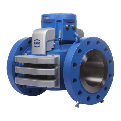
TRZ 03
TRZ 03-K
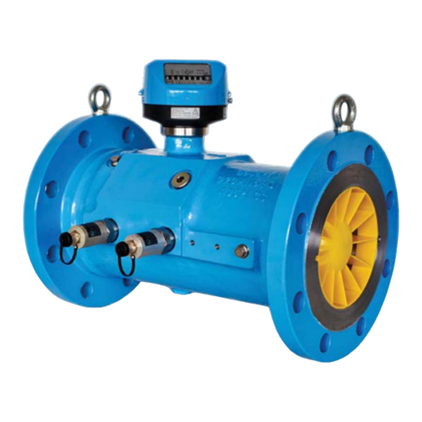
Turbine Meters TRZ 03 and TRZ 03-K
Status: 2018 September, 10th
Version: 08
OPERATING INSTRUCTIONS

Contact
Manual TRZ 03· EN08 2018 September, 10th
Manufacturer
Our customer service is available for technical que-
ries
Address
RMG Messtechnik GmbH
Otto-Hahn-Straße 5
D-35510 Butzbach
Telefon switchboard
+49 6033 897 –0
Telefon service
+49 6033 897 –0
Telefon spare parts
+49 6033 897 –173
Fax
+49 6033 897 –130
E-mail
Original Document
The TRZ03_manual_en_08 from 2018 Septem-
ber, 10th for the turbine gas meter TRZ03 is the
document translated first from the German original
version. Anyhow, this document may serve as ref-
erence for translations into other languages.
Please use in case of any uncertainties the Ger-
man version as main reference.
Note
Unfortunately, paper is not updated automatically,
whereas technical development continuously ad-
vances. Therefore, we reserve the right to make
technical changes regarding the representations
and specifications of these operating instructions.
The latest version of this manual (and other de-
vices) can be downloaded at your convenience
from our Internet home-page
www.rmg.com.
Date created
October 2008
…
5th revision date
November 2017
6th revision date
July 2018
7th revision date
2018 September, 10th
Dokument version and
language
Dokument
Version
TRZ03_manual_en_08
2018 September, 10th
Language
EN

Contents
Manual TRZ 03· EN08 ·2018 September, 10th
I
CONTENTS
1. INTRODUCTION............................................................................................................................1
1.1 OBJECTIVE OFT THE MANUAL............................................................................................................ 1
1.1.1 Abbreviations....................................................................................................................... 1
1.1.2 Symbols................................................................................................................................ 1
1.1.3 Layout of instructions ......................................................................................................... 2
1.1.4 Using the turbine meter TRZ03 ........................................................................................ 3
1.1.4.1 Safety instructions............................................................................................................... 3
1.1.4.2 Hazards during commissioning......................................................................................... 4
1.1.4.3 Danger when using, servicing and maintaining.............................................................. 6
1.1.4.4 Specialized knowledge required....................................................................................... 7
1.1.5 Risk assessment and mitigation ....................................................................................... 8
1.1.6 Validity oft he manual......................................................................................................... 9
1.1.7 Transportation ................................................................................................................... 11
1.1.8 Delivery............................................................................................................................... 11
1.1.9 Dispose of packaging material........................................................................................ 12
1.1.10 Storage............................................................................................................................... 12
1.2 STRUCTURE OF THE MANUAL .......................................................................................................... 13
1.3 OVERVIEW,FUNCTION AND APPLICATION ...................................................................................... 13
1.4 METHOD OF OPERATION.................................................................................................................. 16
1.5 APPROVALS..................................................................................................................................... 17
1.6 STANDARDS /GUIDELINES.............................................................................................................. 18
1.7 VALIDITY OF METER PROVING ......................................................................................................... 18
1.8 MEASURING RANGES....................................................................................................................... 19
1.8.1 Extension of the measuring range.................................................................................. 19
1.9 ACCURACY OF MEASUREMENT........................................................................................................ 20
1.10 TEMPERATURE RANGES .............................................................................................................. 21
1.11 PRESSURE LOSS.......................................................................................................................... 22
1.12 PRESSURE TAP............................................................................................................................ 23
1.13 USING GAS METERS WITH DIFFERENT TYPES OF GASES ............................................................ 23
1.14 INSTALLING THE DEVICE IN THE PIPELINE.................................................................................... 24
2. INSTALLATION AND COMMISSIONING ..................................................................................26
2.1. INSTALLATION.................................................................................................................................. 26
2.2. OPERATING DATA ............................................................................................................................ 28
2.2.1 Threshold........................................................................................................................... 28
2.2.2 Technical Guidline G 13................................................................................................... 29
2.2.3 Perforated-plate straighteners ........................................................................................ 30
2.2.4 Seals................................................................................................................................... 30
2.2.5 Screws................................................................................................................................ 32
3. TYPES OF TOTALIZERS............................................................................................................33
3.1 TYPE „F“ METER HEAD .................................................................................................................... 33
3.2 TYPE “F-D“ METER HEAD ................................................................................................................ 35
3.3 TYPE “A“ METER HEAD .................................................................................................................... 37
3.4 TYPE “D“ METER HEAD.................................................................................................................... 38
3.4.1 Connection of additional equipment............................................................................... 39
3.5 GENERAL......................................................................................................................................... 41
3.6 PULSE TRANSMITTERS .................................................................................................................... 41

Contents
Manual TRZ 03· EN08 2018 September, 10th
II
3.6.1 Connecting additional devices........................................................................................ 43
3.6.2 Pulse transmitters in measuring element (HF 2 and HF 3)........................................ 44
3.6.3 Connector pin assignments............................................................................................. 46
3.7 SPECIFICATIONS OF THE PULSE TRANSMITTERS ............................................................................ 48
3.8 TEMPERATURE MEASUREMENT....................................................................................................... 49
3.9 COMMISSIONING.............................................................................................................................. 50
3.9.1 Filling with oil..................................................................................................................... 50
3.9.2 Connecting the gas flow................................................................................................... 50
4. OPERATION.................................................................................................................................52
4.1 INFLUENCES ON THE ERROR OF MEASUREMENT DUE TO OPERATION............................................ 52
4.1.1 Intermittent operation ....................................................................................................... 52
4.1.2 Influence of pulsations ..................................................................................................... 52
4.1.3 Consequences .................................................................................................................. 53
4.1.4 Limiting values................................................................................................................... 54
4.2 LUBRICATION................................................................................................................................... 55
4.2.1 Lubricator........................................................................................................................... 55
4.2.2 Specification for lubricating oils....................................................................................... 56
4.2.3 Initial lubrication................................................................................................................. 56
4.2.4 Relubrication...................................................................................................................... 56
4.2.5 Lubrication procedure....................................................................................................... 57
4.2.6 Maintenance instructions................................................................................................. 59
5. LABELLING .................................................................................................................................60
6. SPECIFICATIONS........................................................................................................................64
6.1 MEASURING RANGES /DIMENSIONS /PRESSURE CLASSES TRZ03 (PTB) .................................. 64
6.2 MEASURING RANGES /DIMENSIONS /PRESSURE CLASSES TRZ03-K.......................................... 66
6.3 QMIN DEPENDING ON THE OPERATING PRESSURE IN NATURAL GAS ................................................ 68
6.4 VALUES FOR SECONDARY METERING FOR METERS WITHOUT MID APPROVAL.............................. 69
6.5 OVERVIEW OF THE MATERIALS USED.............................................................................................. 70
ANNEX.................................................................................................................................................71
Certificates for LF-/HF-sensors and encoder.............................................................................. 71
Certificates........................................................................................................................................... 73

1 Introduction
Manual TRZ 03· EN08 ·2018 September, 10th
1
1. Introduction
1.1 Objective oft the manual
The manual provides you with the information that is designed for trouble-free and
safe operation.
The TRZ03 is state of the art and conceived and manufactured according to the
recognized safety standards and guidelines. However, risks may arise during use
that can be easily avoided by observing this manual. For this reason, you may only
use the device as intended and in technically sound condition.
Warning
If the TRZ gas meter is not used for its intended purpose, warranty claims
will be void.
1.1.1 Abbreviations
The following abbreviations are used:
ca.
cirka, approximately
as app.
as applicable
max.
maximum
MID
Measurement Instruments Directive
PED (DGRL)
Pressure Equipment Directive (Druckgeräterichtlinie)
min.
minimum
1.1.2 Symbols
The following symbols are used:
1, 2, …
Marks steps within a work operation
..

1 Introduction
Manual TRZ 03· EN08 2018 September, 10th
2
1.1.3 Layout of instructions
The following instructions are used:
Danger
This warning instruction informs you of potentially hazardous situations
that can occur because of incorrect operation or human error. If these situ-
ations are not avoided, they can lead to fatal or severest injuries
Caution
This warning instruction informs you of possible hazardous situations that
can occur because of incorrect operation or human error. If these situa-
tions are not avoided, they can lead to slight or minor injuries.
Notice
This warning instruction informs you of potentially hazardous situations
that can occur because of incorrect operation or human error. If these situ-
ations are not avoided, they can result in material damage to the
device or the vicinity.
This notice may also give to you tips on how to simplify your work. With
this screen, you additionally receive further information on the device or
the work process.
Warning
This warning instruction informs you of possible hazardous situations that
can occur because of incorrect operation or human error. If these
situations are not avoided, they can lead to fatal or severe injuries.

1 Introduction
Manual TRZ 03· EN08 ·2018 September, 10th
3
1.1.4 Using the turbine meter TRZ03
1.1.4.1 Safety instructions
Danger
Observe the following safety instructions!
Non-observance of these safety instructions can lead to a risk of life and
limb and health of the person as well as damage to the environment or
property damage.
Note that the safety instructions in this operating instruction and on the device can-
not cover all possible hazardous situations as the combination of different circum-
stances is impossible to predict. To simply follow the instructions specified may not
normally be sufficient enough to ensure for correct operation. Always be observant
and also consider the following:
•Before working with the device for the first time, read through this operating
instruction and, in particular, follow the safety instructions carefully.
•The operating instruction warns against the residual risks for users, third
parties, devices or other material assets. The safety instructions used refer
to residual risks that cannot be avoided due to the design.
•Operate the device only in a sound state and when observing the operating
instruction.
•Also observe the local legal accident prevention, installation and assembly
guidelines.
Notice
Always keep the operating instructions within reach for use at the place of
installation.
For safe operation, the safety instructions must be observed and followed.
The manufacturer is not responsible for any damage that result as a
consequence of not observing the operating instruction.

1 Introduction
Manual TRZ 03· EN08 2018 September, 10th
4
Danger
Service and maintenance work or repairs that are not described in the
operating instruction must not be carried out without previous
consultation with the manufacturer.
Changes to the device are forbidden.
For safe operation, the technical specifications must be observed and fol-
lowed. Performance limits must not be exceeded
(chapter 6 Specifications).
For a safe operation, the device must only be used in the scope of its
intended use.
Only use the listed set screws, bolts, nuts and gaskets or parts with simi-
lar characteristics for the installation of the meter in the pipeline (chapter
1.14 Installing the device in the pipeline) The device should only be used
under the intended use for safe operation
(chapter 1.3 Overview, Function and Application).
1.1.4.2 Hazards during commissioning
Initial start up
Initial start-up must only be carried out by especially
trained personal (training by RMG) or by service personal
from RMG.
Notice
After the initial start-up an inspection report shall be drawn up. This, the
operation manual and CE declaration of conformity must always be
accessible.
As far as possible all the sharp edges have been eliminated on the device.
Nevertheless, when working on the personal protective equipment must be
used, which must provide the operator.

1 Introduction
Manual TRZ 03· EN08 ·2018 September, 10th
5
Danger
Install the device TRZ03 in accordance with operating instructions. If the
TRZ03 is not installed according to the manual, there is possibly an
insufficient explosion protection.
The explosion protection expires!
Please take care during the installation to the flow direction marked on the
housing by an arrow.
When staff carry out work without sufficient qualification, risks remain
understated when working. Explosion or fire may happen. Perform the
work only if you have the appropriate qualifications and you are an expert.
If you do not use the appropriate tools and materials, components may be
damaged. Use tools that are recommended to you for the job in the
operating instructions.
Mechanical installation
Mechanical installation must only be carried out by the
respectively qualified specialist personnel.
Electrical installation
Installation on components must only be carried out by
qualified electricians.
Mechanical and/or
electrical installation
The specialist personnel require a training especially for
working in potentially explosive environment. Specialist
personnel are persons that can verify a training / further
education according to DIN VDE 0105, IEC 364 or a
similar national standard.

1 Introduction
Manual TRZ 03· EN08 2018 September, 10th
6
Danger
The installation and removal of the TRZ03 or to the TRZ03 connected
convertor may only be carried out in an explosion-free, de-pressurized
atmosphere. It is important to pay attention to the descriptions of the
operation manual during the installation process.
It is generally recommended to ask the RMG Service for any installation or
removal.
After working on pressurized components, a control of leaks must be
carried out.
All points above have to be considered for any repair and maintenance
and in general, when an opening of the meter (convertor) is required.
Parts to lock the flanges, locking screws, fittings and check valves, oil
supply and the pressure tap fittings, valves, HF pulse device, protecting
pipe and rotating adapter may not be opened during operation.
1.1.4.3 Danger when using, servicing and maintaining
Operating personnel
The operating personnel are to use and operate the
device within the scope of the intended purpose.
Maintenance personnel
Work on the device must only be carried out by specialist
personnel that can carry out the respective work assigned
to them as a result of their training, knowledge and
experience as well as the applicable regulations. These
specialist personnel are familiar with the legal guidelines
for accident prevention and can evaluate and avoid
possible risks by themselves.
Maintaining and cleaning
Maintenance and cleaning must only be carried out by the
respectively qualified specialist personnel.
Danger
If staff carry out work without sufficient qualification, risks may be
underestimated when working. Explosion or fire may happen. If work is
carried out in hazardous areas on voltage supporting equipment, resulting
sparks may cause an explosion.

1 Introduction
Manual TRZ 03· EN08 ·2018 September, 10th
7
Danger
If the unit is not cleaned in accordance with the operating instructions, the
device may be damaged. Clean the unit only in accordance with the
operating instructions.
When not using appropriate tools, components can be damaged. The
explosion protection expires.
- Clean with a damp cloth!
Danger
The TRZ 03 may only be used as intended!
(chapter 1.3 Overview, Function and Application).
Avoid any use of the TRZ03 as possible climbing aid or attachments of
TRZ03 as possible handholds!
1.1.4.4 Specialized knowledge required
Notice
Persons working with or on the device must have the following knowledge:
•Training / education for working in potentially explosive environments.
•The ability to correctly assess dangers and risks when using the
device.
•Possible dangers are, e.g., components under pressure or the result of
incorrect installation.
•Recognize dangers that could be caused by the used flow medium.
•Training / education by RMG for working with gas measuring
instruments.
•Education / instruction in all country-specific standards and directives
to be observed for work that is to be carried out on the device.

1 Introduction
Manual TRZ 03· EN08 2018 September, 10th
8
1.1.5 Risk assessment and mitigation
The TRZ03 subjects to risks in its use, which were judged by qualified staff of the
company RMG. Risks may arise due to high pressures, more rarely by too low.
Even work outside the permissible temperature range can lead to danger. Invalid
current and voltage values can trigger explosions in hazardous areas.
The risk assessment assumes that when installing or removing a turbine a drain-
ing and venting of the pipeline takes place. Thus, and only then no explosive gas
mixture is in the pipeline.
Of course (chapter 1.1.4.4 Specialized knowledge required) only work by trained
personnel are permitted, which is also trained to know proper tools and use only
this.
These risks have been considered during the development phase and action were
taken to minimize these risks.
Risk mitigation measures:
- All pressurized parts are designed in accordance to AD 2000 regulations,
PED Annex 1
- The complete design being pressurized is verified by the TÜV Hessen
- All pressurized parts are made with material certificate; there is a
traceability to the batch tracking of all pressurized parts
- The mechanical properties of all relevant pressurized components are
checked by tensile testing, impact testing and hardness testing
- In addition, non-destructive testing was applied: X-ray and ultrasonic
testing of the meter housing for defects in material, surface crack detection
by magnetic particle and dye-penetration
- With pressure tests 1.5 times of the intended operating pressure the
strength of the components were verified; leak test were carried out at 1.1
times of the intended operating pressure. Successful tests were marked
- The maximum operating pressure is stated on the nameplate of the device,
as well as the temperature range. Operation of the device is only permitted
within the indicated ranges.

1 Introduction
Manual TRZ 03· EN08 ·2018 September, 10th
9
Danger
For any work in an explosive atmosphere (all areas):
- The pulse output of the turbine meter has to be connected to
intrinsically safe circuits, only.
- For maintenance and repair work only tool must be used, which is
approved for Ex zone. 1
- Otherwise, work must be carried out only if there is no explosive
atmosphere.
- Danger of ignition caused by impact or friction must be avoided.
- In hazardous areas, the wiring / installation must be performed by
trained personnel in accordance to EN 60079-14 and according to
national regulations
- Skilled persons are in accordance to DIN VDE 0105 or IEC 364, or
comparable standards
- Use only trained and qualified personnel. Work on the measuring
system may only be carried out by qualified personnel and must be
checked by a specialist supervisor.
- Qualified persons are able to carry out such work. Qualification is
valid due to their training, experience or through instruction and
their knowledge of relevant standards, regulations, accident
prevention regulations and plant conditions for the safety of people.
It is essential that these people are able to recognize and avoid
possible dangers.
1.1.6 Validity oft he manual
This manual describes the turbine meter TRZ03. The TRZ03 is only a part of a
complete on-site system. Observe also the instructions of other components of the
site system. If you find contradicting instructions, please contact RMG.
Notice
Make sure that the performance of the power connector corresponds to
the data on the nameplate. Additionally, observe any existing national
regulations in the country. Use cable suitable for the cable glands.

1 Introduction
Manual TRZ 03· EN08 2018 September, 10th
10
Danger
Perform the work only if you have the appropriate qualifications and you
are a trained specialist.
1.1.6.1 Hazards during Operation
Please take care of the information provided by the plant manufacturer and/or
plant manager.
1.1.6.2 Danger during operation in hazardous areas
Operate the device in perfect and complete condition.
When you perform technical modifications to the instrument, a safe operation can
no longer be guaranteed.
Danger
Use the device only in the original condition. The TRZ003 may be operated
in explosion zone 1, but only within the permitted temperatures (chapter
1.10 Temperature ranges).
1.1.6.3 Operator responsibility
Take care as plant manager that only sufficiently skilled personnel will work on the
device. Ensure that all employees who handle the equipment have read and un-
derstood these instructions. Additionally, you are obliged to train staff on a regular
basis and to inform them about any dangers. Ensure that any work carried out on
the device is done by qualified personnel and checked by responsible specialists.
You must establish clearly the responsibilities for installation, operation, trouble-
shooting, maintenance and cleaning.
Point out to your staff any risks involved when using the device.

1 Introduction
Manual TRZ 03· EN08 ·2018 September, 10th
11
1.1.7 Transportation
The device is packaged customized according to the transport requirements.
Warning
Risk of injury during transport
Any foot screws must be fitted, if they are used as transit protection against
rolling and tipping. Take additional care that a rolling and tilting is safely pre-
vented.
To lift the meter only the special lifting eyes / eye bolts may be used. Pay at-
tention to the maximal loads for the lifting devices (chapter 6 Specifications)
–don’t exceed those. Make sure that the load is fastened securely before lift-
ing. Do not stand under lifted loads.
During lifting and/or depositing the device may slip, tip over or fall.
Disregarding the maximum load capacity of the lifting device, the device may
fall down. For any people standing nearby, there is a significant risk of seri-
ous injury.
If the unit is supplied on a Euro pallet, the unit can be transported using a lift
truck or a forklift. During the transport the meter has to be protected against
shock or vibration.
The meter or its additionally mounted spool pieces are equipped with flanges
that are protected with a sticker foil or blind plugs made of plastic. These
must be removed completely before installation in the pipeline. Remaining
rests of these protections may change the flow pattern and may result in a
measurement error! For any transport e.g. for recalibration we ask you to use
these protections.
1.1.8 Delivery
Supplied number of parts may differ depending on the optional customer order.
"Usually" the following is included in the scope of delivery:
Teil
Quantity
Turbine meter TRZ 03
1
1 small bottle of oil for lubrication
1
Manual
1
Test report
1

1 Introduction
Manual TRZ 03· EN08 2018 September, 10th
12
Calibration certificate
1
Certificat for
- Strength 3.1 and
- tightness
…
…
1.1.9 Dispose of packaging material
Dispose the packing material in an environmentally friendly way in accordance to
the national standards.
1.1.10 Storage
Avoid long periods of storage. Check the device after any storage for damage and
functionality. Ask for a check from the RMG service after a storage period for the
device of over one year. In this case please send the device to RMG.
Notice
For storage, a dry and protected space has to be provided.
It is important to ensure that all open pipe pieces must be sealed.

1 Introduction
Manual TRZ 03· EN08 ·2018 September, 10th
13
1.2 Structure of the manual
The introduction of this manual contains two parts. In the first part general guide-
lines are listed; the symbols used and structure of advices are given, but the risk
assessment is also issued. In addition, it contains guidelines for the transport and
storage of the TRZ03. The second part introduces the operation of TRZ03; there
are basic standards listed; pressure and temperature ranges are given limiting the
use of the TRZ03.
The second chapter describes the use of TRZ03. It explains how a high accuracy
can be achieved. The third chapter describes various totalizer heads, their proper-
ties and connection options. The forth chapter provides recommendations on how
the current operation can be ensured. These include the accuracy influencing flow
disturbances as well as regular lubrication of the bearings of the turbine meter.
The fifth chapter describes the marking of the TRZ03 and in the sixth the technical
data of TRZ03 are summarized. The appendix includes details to the previous
chapters, a summary of certificates and approvals.
1.3 Overview, Function and Application
The TRZ 03 turbine meters are flow meters which can be used for custody transfer
metering. Or more precisely for measuring the volume at measurement conditions
of non-aggressive gases and fuel gases. The TRZ 03-K turbine meter can only be
used for secondary metering.
All types of turbine meters measure the quantity of gas flowing through them in
units of volume at prevailing pressure and temperature. Therefore, the units of vol-
ume are determined at flowing conditions. The volume of the gas flowing through
is indicated by a mechanical totalizer in cubic meters at flowing conditions. In addi-
tion, the turbine meters can be fitted with HF or LF pulse transmitters and with
reed contacts. In this way, pulses are obtained whose number is proportional to
the volume which has flowed through. These pulses can be further processed by
volume correctors.
The major differences between types TRZ 03 and TRZ 03-K are as follows:
TRZ 03
•Approved for custody transfer metereing according to DIN 33800
•Installation length: 3 x DN
•Accuracy 0.5% (above 0,2 Qmax)
•Blade monitoring system

1 Introduction
Manual TRZ 03· EN08 2018 September, 10th
14
TRZ 03-K
•For secondary metering
•Installation length: 1,5 x DN
•Accuracy 1% (above 0,2 Qmax)
The following applies to all meter types:
•Maximum operating pressure: 100 bar
(not for gas meters with a plastic turbine wheel)
•Meter sizes from G 40 to G 16000
•Measuring range 1:20 (MID); applying a high-pressure certification, a range
of up to 1:160 is also possible (see data sheets)
•Connections in compliance with DIN or ANSI are available.
•Special designs for aggressive gases are available.
•Available for low temperatures (< 10°C)
•All gas meters can be operated in any position up to the nominal diameter
of DN 200.
The TRZ 03 and TRZ 03-K are used for measuring the volume at measurement
conditions of non-aggressive gases and fuel gases. Measurements of aggressive
gases are only permitted if the special designs are used which have been
developed for this purpose.
The TRZ 03 und TRZ 03-K are approved for the use in explosive areas; the
indication is:
II 1G Ex ia IIC T4 (HF sensors)
The corresponding conformity certificates for the LF und HF sensors can be found
in the appendix.
Information about temperature limits are given in chapter 1.10 Temperature
ranges.
The TRZ 03 meets the standards, guidelines and regulations:
Chapter 1.6 Standards / Guidelines and the Annex
These technical limitations you must comply with the TRZ03 for safe operation:
Chapter 6 Specifications

1 Introduction
Manual TRZ 03· EN08 ·2018 September, 10th
15
The device may only be operated with the following types of gases (chapter 1.13
Using gas meters with different types of gases). Only with these stated gases a
safe operation is ensured:
• Gases of class 1
• Gases of class 2
• Gases of class 3
The friction of the gas components must be within the limits in accordance with the
EN 437:2009 for test gases.
The following instructions must be observed:
Notice
The RMG TRZ 03 und TRZ 03-K can be operated in any mounting
orientation up to DN200, from the DN 250 is a horizontal orientation is
required.
If a mounting orientation is specified when ordering, the meter has to be
installed in this orientation.
It is also important to ensure that the filling port of the lubricator faces
upwards.

1 Introduction
Manual TRZ 03· EN08 2018 September, 10th
16
1.4 Method of operation
The method of operation of the mechanical turbine meter is based on the meas-
urement of the gas velocity. The velocity of the gas flowing through the gas meter
is increased in the flow straightener and the gas strikes the turbine wheel in a de-
fined flow cross section. In the flow straightener, un¬wanted vortices, turbulences
and asymmetries are removed or reduced. The turbine wheel is mounted axially,
while the blades of the turbine wheel are arranged at a certain angle to the gas
flow. Within the measuring range (Qmin - Qmax), the rotational speed of the turbine
wheel is almost proportional to the mean gas velocity and, therefore, to the rate of
flow. The number of rotations is a measure of the volume that has flowed through.
The rotary movement of the turbine wheel is transmitted by a magnetic coupling to
the unpressurized meter head. Downstream of the coupling, there is an HF pulse
transmitter (HF 1) and gearing which reduces the rotational speed of the turbine
wheel to match the mechanical totalizer. An LF pulse transmitter (slot-type initiator
or reed contact) is located on the totalizer.
Figure 1: Sectional drawing of a turbine meter shows a sectional drawing of a tur-
bine meter TRZ03. Downstream of the turbine wheel, a cam wheel (reference
wheel) is located on the same shaft. Two HF sensors (proximity switches) gener-
ate a signal if a blade of the turbine wheel (HF 3) or a cam of the reference wheel
(HF 2) passes them. In this way, two pulse sequences are generated which are
out of phase. The generated pulses can be further processed for secondary vol-
ume measurements or flow measurements.
A counter with an integrated encoder (e.g. ENCO 08) processes the pulse se-
quences. The totalizer (Vo) can be transmitted digitally to a flow computer. The
necessary pressure and temperature values can be recorded in the pr connection
(pressure) and via one (or more) temperature sensors in the immersion pocket.
This manual suits for next models
1
Table of contents
Other RMG Measuring Instrument manuals
Popular Measuring Instrument manuals by other brands
Unimax
Unimax LM 63A user manual

Kyoritsu Electrical Instruments Works, Ltd.
Kyoritsu Electrical Instruments Works, Ltd. KEW 8343 instruction manual

AU Tool
AU Tool X91 TPMS user manual
Phase Technologies
Phase Technologies 70Xi Series Replacement

Homeline
Homeline CL-2 instruction manual

B+K precision
B+K precision PR65 Series user manual

