RMG TERZ 94 User manual

Reliable Measurement of Gas
Electronic Turbine Meter TERZ 94
OPERATING INSTRUCTIO
NS
STATUS: 2017 November, 20
th
Version: 09a

...............................................................................................................................................................................................................
...............................................................................................................................................................................................................
Manual TERZ 94 · EN09a · 2017-11
Manufacturer
Our customer service is available for technical ueries
A ress RMG Messtechnik GmbH
Otto-Hahn-Straße 5
D
-
35510 Butzbach
Telefon
switchboar
+49 6033 897
–
0
Telefon service
+49 6033 897
–
127
Telefon spar
e parts
+49 6033 897
–
173
Fax
+49 6033 897
–
130
E
-
mail
Original Document
The manual TERZ94_manual_en_09a from 2017
November, 20
th
for the electronic gas meter TERZ 94 is
the document translated first from the German original
version. Anyhow, this document may serve as reference
for translations into other languages. Please use in case
of any uncertainties the German version as main
reference.
Note
Unfortunately, paper is not updated automatically,
whereas technical development continuously advances.
Therefore, we reserve the right to make technical
changes in regard to the representations and
specifications of these operating instructions. The latest
version of this manual (and other devices) can be
downloaded at your convenience from our Internet
home-page
www.rmg.com
.
Date create
July
20
09
1
st
revision ate
January
201
1
…
9
th
revision ate
Febr
uary
2015
9
th
a
revision ate
2017 November, 20
th
Document version an
language
Document
version
TERZ94_manual_en_09a
2017 November, 20
th
Language
EN

CONTENTS
...............................................................................................................................................................................................................
...............................................................................................................................................................................................................
Manual TERZ 94 · EN09a · 2017-11
INTRODUCTION .................................................................................. 1
FUNCTIONAL DESCRIPTION .............................................................. 2
Construction............................................................................................................ 2
Meter head ..............................................................................................................
Block diagram .........................................................................................................
SAFETY INSTRUCTIONS ..................................................................... 6
Instructions for the installer .................................................................................. 7
Marking ....................................................................................................................... 7
Use .............................................................................................................................. 7
Installation or remo al ................................................................................................. 8
Installation ................................................................................................................... 8
Commissioning ............................................................................................................ 8
Ser icing and maintenance .......................................................................................... 8
Modifications to the product ........................................................................................ 8
INSTALLATION ................................................................................... 9
Operating conditions .............................................................................................. 9
Permissible types of gases ........................................................................................... 9
Permissible temperature ranges ................................................................................... 9
Pressure loss ........................................................................................................... 9
Installation ............................................................................................................ 10
Seals ......................................................................................................................... 11
Screws ...................................................................................................................... 12
Meter head ............................................................................................................ 1
Electrical connections .......................................................................................... 1
Earthing ..................................................................................................................... 15
Cables ....................................................................................................................... 16
Cable glands .............................................................................................................. 17
Installing the remote totalizing unit .................................................................... 18
START-UP ......................................................................................... 19
Connecting the gas flow ....................................................................................... 19
Initializing the totalizing unit ................................................................................ 19
OPERATION ...................................................................................... 20
Display ................................................................................................................... 20
Programming ......................................................................................................... 22
Principle of programming ........................................................................................... 24
Display alues ............................................................................................................ 24
Parameters and Modes of the TERZ 94 / 94-S ................................................... 25

CONTENTS
...............................................................................................................................................................................................................
...............................................................................................................................................................................................................
Manual TERZ 94 · EN09a · 2017-11
1. Meter factor (pulse alue) TERZ 94 / 94-S ............................................................. 25
2. LF pulse scaler ....................................................................................................... 26
3. Configuration ......................................................................................................... 27
4. Pulse comparator ................................................................................................... 29
5. Flow rate at 4 mA .................................................................................................. 29
6. Flow rate at 20 mA ................................................................................................ 29
7. Current default alue (calibration current) .............................................................. 29
8. Current output mode ............................................................................................. 30
9. Current damping .................................................................................................... 30
10. Correction factors for current offset and current rise ........................................... 30
POWER SUPPLY ............................................................................... 1
MAINTENANCE ................................................................................. 2
Lubrication ............................................................................................................ 2
Changing the battery ............................................................................................
SPECIFICATIONS .............................................................................. 4
Measuring range ................................................................................................... 4
Measuring error .................................................................................................... 4
Temperature ranges ............................................................................................. 4
Inputs and outputs ............................................................................................... 4
Sensor input S1 (Measuring input) ............................................................................ 34
Sensor input S2 (Comparati e input or start/stop/reset) .......................................... 35
HF output .................................................................................................................. 35
LF output ................................................................................................................... 36
Alarm output .............................................................................................................. 36
Vo or RS-485 data interface ....................................................................................... 37
Temperature input (hardware and software options) .................................................. 38
Current-loop connection (TERZ 94-S only!) ................................................................. 38
Data for the use in hazardous areas: .......................................................................... 38
Materials used for the meter case ....................................................................... 8
Examples of connection ....................................................................................... 9
Battery-operated de ice ............................................................................................. 39
Main-powered de ice (Ex design) ............................................................................... 40
Main-powered de ice (Non-Ex design) ........................................................................ 41
ANNEX .............................................................................................. 42
Overview of Parameters for the TERZ 94/94-S .................................................. 42
Standard Parameters (values set in the factory) up to DN 150 ........................ 4
Fault and Event Display (coordinate A09) ........................................................... 45
Reset ...................................................................................................................... 46
Booting .................................................................................................................. 46
Matrix of the TERZ 94 / 94-S ............................................................................... 47

CONTENTS
...............................................................................................................................................................................................................
...............................................................................................................................................................................................................
Manual TERZ 94 · EN09a · 2017-11
TERZ 94 Button Assignments ............................................................................... 48
Converting the TERZ 94 into the TERZ 94-S ........................................................ 49


INTRODUCTION
...............................................................................................................................................................................................................
...............................................................................................................................................................................................................
Manual TERZ 94 · EN09a · 2017-11
1
Introduction
The TERZ 94 / 94-S turbine meter complements the RMG TRZ 03, TRZ 03-L and TRZ 03 K turbine
meters (see RMG Publication Nos. 3.161-E and 3.171-E).
The TERZ 94 / 94-S directly measures the flow rate at measurement conditions and integrates the
measured alues, so that, as a result, the gas olume which flowed through the meter is registered
by an electronic totalizing unit. The gas flow dri es a turbine wheel whose speed is recorded
through non-contact measurement by a sensor. Therefore, the meter is characterized by long-term
stability and low wear.
The TERZ 94 / 94-S is pro ided with HF and LF outputs which allow the de ice to be used as a flow
transducer for control applications and remote transmission.
Features
− For secondary applications
− With electronic totalizing unit
− Flow display
− Display of maximum flow alues
− Alarm output
− Detachable meter head (for use as a remote totalizer)
− Digital transmission of meter readings
The two ariants TERZ 94 and TERZ 94-S differ in the following features:
TERZ 94
− Battery operation
− Electronic suppression of the slow-down effect of the turbine wheel after flow stop by
external shut-down of the totalizer
TERZ 94-S
− External power supply
− 4-20
mA current output for outputting the flow rate
FUNCTIONAL DESCRIPTION
...............................................................................................................................................................................................................
...............................................................................................................................................................................................................
Manual TERZ 94 · EN09a · 2017-11
2
Functional Description
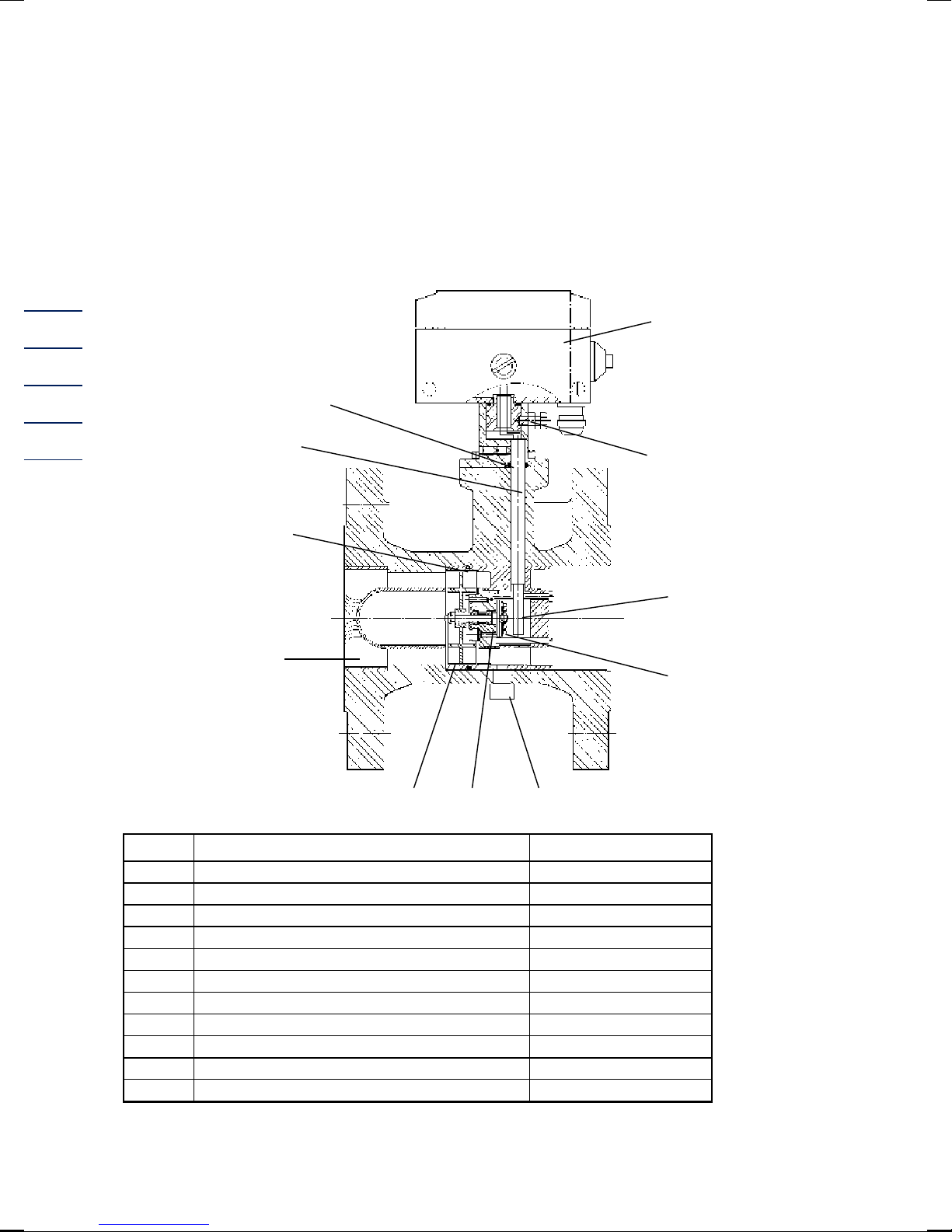
Construction
Part Designation Material
1 Meter head
2 Set screw Steel
3 Sensor WF01 (1-channel) or WF02 (2-channels)
4 Permanent magnet Oerstit 500
5 Lubricator (from DN 200)
6 Radial ball bearing Nirosta steel
7 Turbine wheel Delrin / aluminium
8 Flow straightener Hostaform
9 O-ring
10 Sensor slee e with sensor Nirosta steel
11 O-ring 8x2.5 83FKM592
1
11
2
3
10
9
8
4
7 6 5

FUNCTIONAL DESCRIPTION
...............................................................................................................................................................................................................
...............................................................................................................................................................................................................
Manual TERZ 94 · EN09a · 2017-11
3
The TERZ 94
/
94-S olumeters form a series of uniform construction.
The meters consist of the following principal components:
- meter case
- measuring element (with turbine wheel and sensor) and
- electronic totalizing unit.
An aerodynamic flow straightener (8) fitted into the meter case constricts the effecti e cross
section of the pipe to form a ring-shaped cross-sectional area and substantially eliminates
turbulences. The elocity of the flowing gas increases and the gas is directed to the turbine blades.
The turbine wheel (7) is dynamically balanced and mounted with dust-proof ball bearings (6). A
permanent magnet (4) located at the end plate of the turbine shaft induces the sensor element (3)
to gi e a oltage pulse with each rotation of the turbine wheel. This pulse is further processed by
the electronic system of the meter head (1).
Meter head
Inside the meter head, the number of pulses is di ided by the meter factor (number of pulses per
m3) and the result is used to calculate the olume at measurement conditions. In the main totalizer,
the sum of the olume at measurement conditions which flowed through the meter is formed and
you can read the gas olume which flowed through the meter per time unit on the flow rate display.
At the HF output, the unchanged signal frequency of the sensor element is outputted, whereas, for
the LF output, this HF frequency can be reduced by two programmable scaling factors.
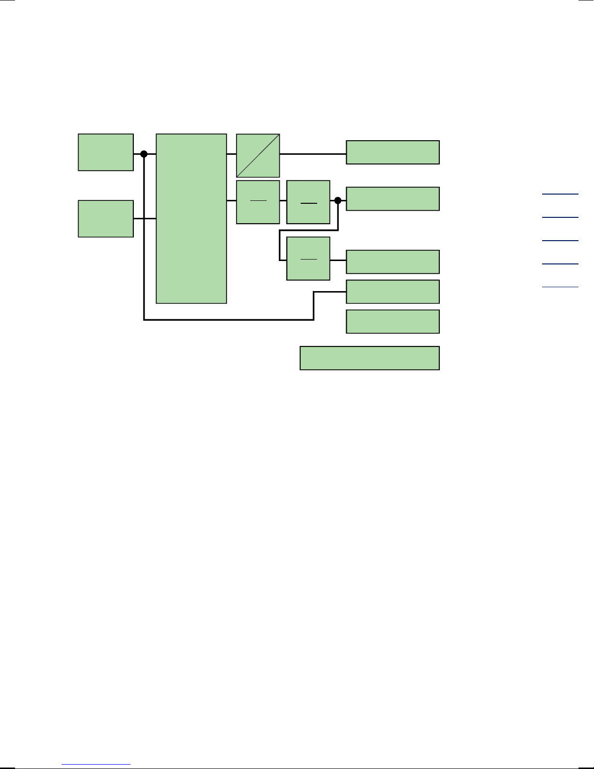
Block diagram
TERZ 94
In the display field of the TERZ 94 (not with the TERZ 94-S), a start-stop totalizer or a resettable
totalizer can be optionally displayed. Through the free sensor input X5, either the olume metering
of the start-stop totalizer is interrupted or the resettable totalizer is reset (depending on the
programming of the TERZ 94).

FUNCTIONAL DESCRIPTION
...............................................................................................................................................................................................................
...............................................................................................................................................................................................................
Manual TERZ 94 · EN09a · 2017-11
4
TERZ 94-S
The TERZ 94-S olumeter has a current-loop connection (X2_0 with current module TERZ94trm)
which ser es as power supply and 4 to 20 mA current output at the same time. For this purpose, a
power supply unit is required which is to be connected to this output.
The TERZ 94-S cannot be battery-operated.
TERZ 94 1-channel
Channel 1
Start/Stop
Reset
1
K
12345678 m3
HF output
LF output
1
n
f
i
Current output
1
n
Alarm contact
Option:
EZD or RS485 interface
FUNCTIONAL DESCRIPTION
...............................................................................................................................................................................................................
...............................................................................................................................................................................................................
Manual TERZ 94 · EN09a · 2017-11
5
TERZ 94 2-channel
Channel 1
Channel 2
1
K
12345678 m3
HF output
LF output
1
n
f
i
Current output
1
n
Alarm contact
Option:
EZD or RS485 interface
With 2 channels:
pulse
monitoring
10 / 10000
180 °
SAFETY INSTRUCTIONS
...............................................................................................................................................................................................................
...............................................................................................................................................................................................................
Manual TERZ 94 · EN09a · 2017-11
6
Safety Instructions
The TERZ 94 / 94-S olumeter is used for measuring the olume at measurement conditions of
non-corrosi e gases and fuel gases. Measurement of corrosi e gases is only permitted if the special
designs are used which ha e been de eloped for such purpose. These meters are not suitable for
measuring liquids, otherwise they will be destructed.
The TERZ 94 / 94-S complies with currently applicable standards and regulations. Howe er, failure
to operate them properly may cause hazards.
Persons who install or operate the TERZ 94 / 94-S olumeter in areas subject to explosion hazards,
must be familiar with the currently applicable explosion protection standards and regulations.
The electronic totalizing unit of the explosion-protected design has been appro ed for use in areas
subject to explosion hazards and its code is:
II 2 G EEx ib[ia] IIC T , T4
The appropriate certificate of conformity can be found in the annex and its reference number is:
TÜV 02 ATEX 1970
Please obser e the following signs:
Danger of explosion
In the manual, this symbol warns you of an explosion hazard. Please obser e the
instructions gi en next to this symbol. As to the danger of explosion, please note the
following in particular:
• Only the explosion-protected design of the TERZ 94
/
94-S may be used in areas
subject to explosion hazards. Connect the pulse outputs of these de ices only to
intrinsically safe circuits.
• The battery must be changed in an area without explosion hazards.
• The specifications on cable type and cable length in this manual and in the ex-
appro al must be obser ed.
• Modifications to the de ice make the Ex appro al in alid and are therefore prohibited.
Damage to property
In the manual, this symbol warns you of possible damage to property. The instructions
gi en next to this symbol inform you about what you can do to a oid damage to the
TERZ 94 olumeter.
It is essential to obser e the warning information in these operating instructions and the generally
applicable safety rules.
No warranty claims can be asserted if there is unauthorized interference with the de ice!

SAFETY INSTRUCTIONS
...............................................................................................................................................................................................................
...............................................................................................................................................................................................................
Manual TERZ 94 · EN09a · 2017-11
7
Instructions for the installer
Marking
II 2 G Ex ib[ia] IIC T4 or T3
TÜV 02 ATEX 1970 / IECEx TUN 09.0002
Ta = -25°C ..... +40 / 60°C
For data, see the EG type examination certificate (see annex)
0044
0085
Manufacturer
RMG Messtechnik GmbH
Otto-Hahn-Straße 5
D-35510 Butzbach (Germany)
Use
Device type Description
TERZ 94*** Volumeter
EA **** Volumeter
EZ **** Volumeter
TRZ 03-*** Turbine meter
ENCO-* Encoder index
EC 21 Temperature corrector
EC 24 Volume corrector
TEC 21 Volumeter + temperature corrector
TEC 24 Volumeter + olume corrector
ETC **** Volumeter + temperature corrector
EVC **** Volumeter + olume corrector
This de ice is an apparatus for areas subject to explosion hazards.

SAFETY INSTRUCTIONS
...............................................................................................................................................................................................................
...............................................................................................................................................................................................................
Manual TERZ 94 · EN09a · 2017-11
8
Installation or removal
When installing the de ice, care must be taken that the degree of protection of the casing is
complied with. Exposure to direct sunlight has to be a oided.
When remo ing the de ice, de-energize the signal circuits connected and remo e the rele ant
cables properly.
Installation
If one or more than one signal circuit is used, make sure when choosing the cables that the
permissible limits as per the EC type examination certificate are not exceeded.
Each explosion-protected signal circuit has to be installed in a separate cable which is to be taken
through the rele ant high-strength cable gland.
It is absolutely necessary that the intrinsically safe cables are permanently installed.
Make sure that the connecting cables are pro ided with wire-end slee es.
Commissioning
Before commissioning this equipment, make sure that all lines ha e been correctly installed and
connected in the terminal compartment.
The casing must be completely closed.
For installation and commissioning, the IEC 60079-14 of 2004 / EN 60079-14 of 2006 standard
has to be complied with.
National norms and/or regulations also need to be taken into consideration.
Servicing and maintenance
The battery may only be changed in a non-incendi e area.
This de ice may be repaired only by RMG Messtechnik.
Modifications to the product
Changes or modifications made to this product by unauthorized persons may lead to incorrect
malfunctions and are prohibited for safety reasons! In this case the [ATEX] appro al will be no
longer alid.
This de ice may be repaired only by RMG Messtechnik!

INSTALLATION
...............................................................................................................................................................................................................
...............................................................................................................................................................................................................
Manual TERZ 94 · EN09a · 2017-11
9
Installation
Operating conditions
Permissible types of gases
The standard design of the TERZ 94 or TERZ 94-S can be used for all non-corrosi e gases, such as
Natural gas Air
Town gas Argon
Methane Helium
Ethane Carbon dioxide (dry)
Propane Nitrogen
Butane Hydrogen
Special designs (PTFE lining, special lubrication, special material, etc.) can be used for corrosi e
and humid gases, such as
Ethylene Digester gas
Biogas Sulphur dioxide
Acid gas etc.
Permissible temperature ranges
For the standard design, the following fluid temperature and ambient temperature ranges are
permitted:
Fluid temperature range: -10°C to +50°C
Ambient temperature range: -20°C to +60°C resp. +40°C
Pressure loss
The pressure loss is calculated using the following formula:
4
2
M
P
DN
Q
Z=p ⋅ρ⋅∆
where
∆p is the pressure loss [mbar]
ZP is the pressure loss coefficient
ρ is the density [kg/m3]
QM is the flow rate at measurement conditions [m3/h]
DN is the nominal diameter of the meter [mm]

INSTALLATION
...............................................................................................................................................................................................................
...............................................................................................................................................................................................................
Manual TERZ 94 · EN09a · 2017-11
10
The pressure loss coefficient ZP is constant for all olumeters of the types TERZ 94 and TERZ 94-S.
It is:
Z
P
= 5040
This is an approximate mean alue. The exact alue is calculated from the pressure loss which is
determined on testing the olumeter.
Example of calculation:
Q
M
= 650 m
3
/h; DN 150; ρ = 1.3 kg/m
3
[natural gas, 600
mbar]
mbar5.5
150
650
3.15040
DN
Q
Z=p
4
2
M
P
4
2
=⋅⋅=⋅ρ⋅∆
Therefore, the pressure loss ∆p with a olumeter of the type TERZ 94 is 5.5 mbar in this case.
Installation
The gas flow must be free of shocks and pulsations as well as free of foreign particles, dust and
liquids. Any components affecting the gas flow must absolutely be a oided directly upstream of the
TERZ 94 olumeter.
To achie e the highest possible accuracy (measuring error <1%), an inlet pipe of 2 DN in length with
a perforated-plate straightener should be installed upstream of the meter.
You can install the meters in any position ( ertical or horizontal) up to and including the nominal
diameter of DN 200. From the nominal diameter of DN 250, only the position stated in the
purchase order is possible.
When you install the volumeter, please observe the direction of flow indicated on the case!

INSTALLATION
...............................................................................................................................................................................................................
...............................................................................................................................................................................................................
Manual TERZ 94 · EN09a · 2017-11
11
Seals
It must be guaranteed that flange seals of RMG turbine meters do not protrude from the flange into
the gas line.
All seals appro ed as per DVGW can be used depending on the requirements for stability and reli-
ability.
We recommend seals with the following maximum material characteristic alues according to the
AD2000 rules:
− gaskets: k
0
x K
D
= 20 x b
D
| k
1
= 1.3 x b
D
[N/mm]
− groo ed seals: k
0
x K
D
= 15 x b
D
| k
1
= 1.1 x b
D
[N/mm]
− spiral seals: k
0
x K
D
= 50 x b
D
| k
1
= 1.4 x b
D
[N/mm]
− octagonal ring joint seal: K
D
= 480 N/mm
2
For recommended dimensions, see the tables below.
Gaskets PN 10 PN 16 ANSI 150
PN 25 PN 40
DN d1 d2
50 2" 77 107 107 105 107 107
80 3" 90 142 142 137 142 142
100 4" 115 162 162 175 168 168
150 6" 169 218 218 222 225 225
200 8" 220 273 273 279 285 292
250 10" 274 328 330 340 342 353
300 12" 325 378 385 410 402 418
400 16" 420 490 497 514 515 547
500 20" 520 595 618 607 625 628
600 24" 620 695 735 718 730 745
Grooved seals ANSI 300
/
ANSI 600 PN 64
DN d1 d2 d1 d2
50 2" 69,8 88,9 65 87
80 3" 98,4 123,8 95 121
100 4" 123,8 154,0 118 144
150 6" 177,8 212,7 170 204
200 8" 228,6 266,7 220 258
250 10" 282.6 320.7 270 315
300 12" 339.7 377.8 320 365
400 16" 422.3 466.7 426 474
500 20" 530.2 581.0 530 578
600 600 631.8 682.6 630 680
1.5 up to 5 mm
d1
d2
INSTALLATION
...............................................................................................................................................................................................................
...............................................................................................................................................................................................................
Manual TERZ 94 · EN09a · 2017-11
12
Spiral
seals
ANSI 300 PN 64 ANSI 600
DN d1 d2 D1 d2 d1 d2
50 2" 69.9 85.9 66 84 69.9 85.9
80 3" 101.6 120.7 95 119 101.6 120.7
100 4" 127.0 149.4 120 144 120.7 149.4
150 6" 182.6 209.6 174 200 174.8 209.6
200 8" 233.4 263.7 225 257 225.6 263.7
250 10" 287.3 317.5 279 315 274.6 317.5
300 12" 339.9 374.7 330 366 327.2 374.7
400 16" 422.4 463.6 426 466 412.8 463.6
500 20" 525.5 577.9 530 574 520.7 577.9
600 24" 628.7 685.8 630 674 628.7 685.8
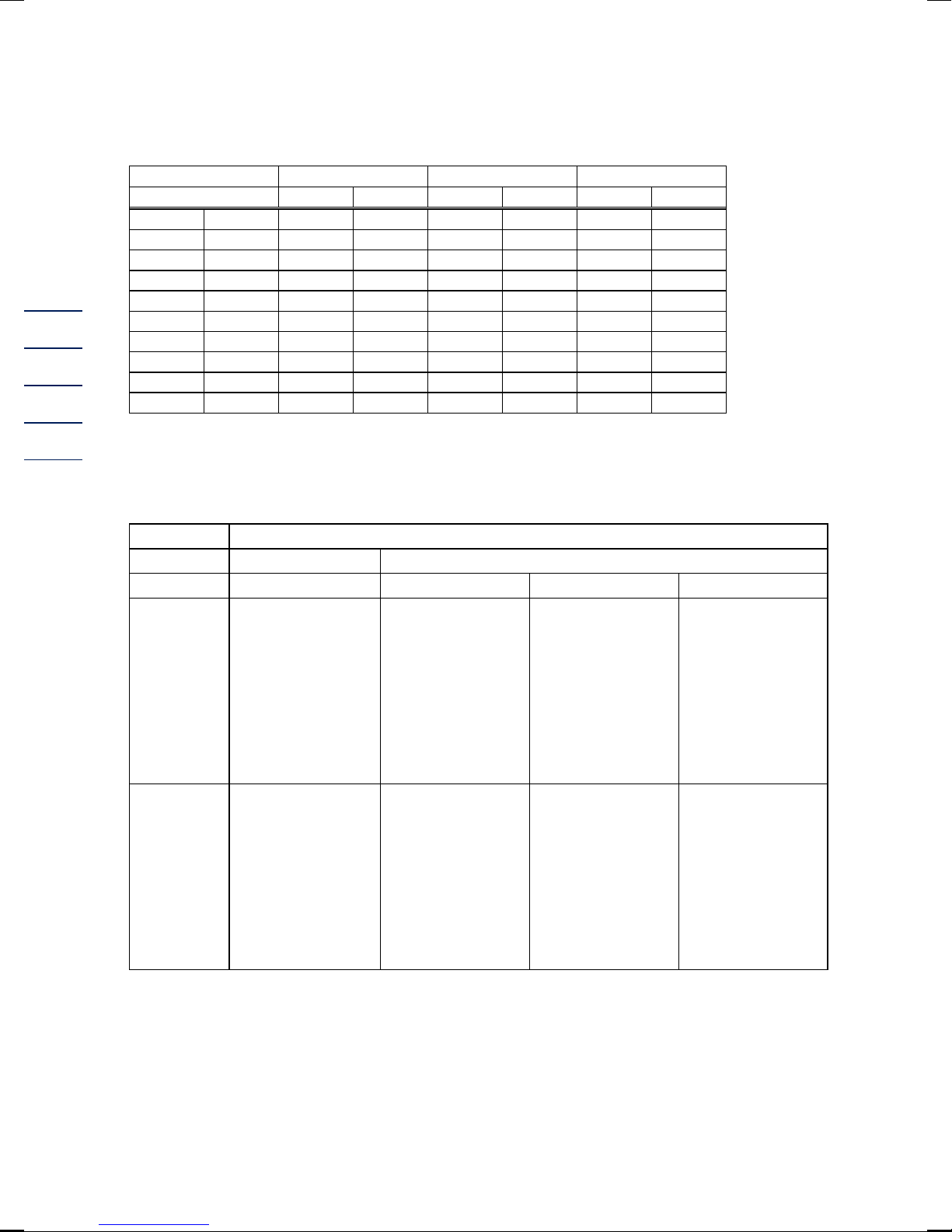
Screws
Temperature ranges for screws and nuts
-10°C to +80°C -40°C to +80°C
Pressure Variant 1 Variant 2 Variant 3
up to and
including
40 bar
Screws complying
with
DIN EN ISO 4014
made of material 5.6,
Nuts complying with
DIN EN ISO 4032
made of material 5-2
Screws complying
with
DIN EN ISO 4014
made of material
25CrMo4,
Nuts complying with
DIN EN ISO 4032
made of material
25CrMo4
from 40 bar
Screw bolts complying
with
ANSI B1.1
made of material
ASTM A193 Grade B7,
Nuts complying with
ANSI B1.1
made of material
ASTM A194 Grade 2H
Screw bolts
complying with
ANSI B1.1
made of material
ASTM A320 Grade L7,
Nuts complying with
ANSI B1.1
made of material
ASTM A320 Grade L7
Screw bolts
complying with
ANSI B1.1
made of material
42CrMo4,
Nuts complying with
ANSI B1.1
made of material
42CrMo4
Anti-fatigue bolts
complying with DIN
2510
made of material
25CrMo4,
Nuts complying with
DIN 2510
made of material
25CrMo4

INSTALLATION
...............................................................................................................................................................................................................
...............................................................................................................................................................................................................
Manual TERZ 94 · EN09a · 2017-11
13
Meter head
The meter head (1) can be turned after the set screw (2) has been loosened. Turn the meter head
by max. 360°, otherwise the signal wires can become twisted and break.
You can install the meter head also ertically. To do this, you must proceed as follows:
• Unscrew the co er of the meter head.
• Disconnect the two wires from terminal X5 (remember the polarity!).
• Loosen the set screw (2). Now you can remo e the case of the meter head and an aluminium
assembly part will appear.
• On the side of the case, there is a hole which is co ered with a screw. Mount the retainer part
to this hole and close the hole in the rear panel by means of the screw.
• Thread the signal wires through the retainer part, place the meter head onto the turbine case,
turn it into the desired position and retighten the set screw (2).
• Connect the signal wires again to terminal X5 (make sure that the polarity is correct!) and screw
on the co er again.
Electrical connections
The LF and HF olume pulses and the alarm output are led out of the meter head by a 7-pin
connector (Binder). All other connections ha e to be made at the terminals on the board.
Standard connection TERZ 94 and TERZ 94-S:
The supply/current-loop (TERZ 94-S only) is connected to the terminals X22 on the transmitter
board TERZ94trm.
In areas subject to explosion hazards, the TERZ 94 must only be connected to certified
intrinsically safe circuits.
Make sure that the limiting alues from the conformity certificate (see appendix) for
the de ices, which ha e to be connected, are not exceeded.
If one or more electric circuits are used, it is to ensure that with the cable selection the permissible
limiting alues according to the EEC design inspection certificate are not exceeded.
Each ex signal circuit has to be wired in its own cable, which is to be led through the appropriate
cable gland.
A fixed installation of the intrinsically safe cables is mandatory.
The connecting cables ha e to be pro ided with core-end slee es.
1
2
3
4
5
PE (Abschirmung)
6
1 - / 4 + LF signal
2 - / 5 + Alarm
3 - / 6 + HF signal
PE (Screening)

INSTALLATION
...............................................................................................................................................................................................................
...............................................................................................................................................................................................................
Manual TERZ 94 · EN09a · 2017-11
14
To reach the electrical connections on the board, you must first remo e the co er of the meter
head.
To con ert from the meter head directly mounted on the meter case to the remote totalizing unit
and ice ersa it is necessary to change the positions of some jumpers (see inputs and outputs in
the annex).
X_S1 X_S2 X_TERZ90
Meter head mounted on
meter case
3-5 and 4-6 3-5 and 4-6 all open
Remote totalizing unit 3-4 3-4 1-2 and 3-4
Start / stop totalizer 3-5 and 4-6 1-3 and 2-4 all open
TERZ 94:
Controlling the start-stop totalizer or resetting the resettable totalizer (depending on the
programming of the electronic totalizing unit) is performed through input X5 terminals 3 and 4.
As soon as input X5 terminals 3 / 4 has been short-circuited through an external contact,
interruption or resetting is performed.
⇒ For this purpose, set jumpers at the positions identified with XS 2 to the “reed contact” function.
Pin connector button on the case
Reset
Terminal X5
Pulse inputs
Plug X2_0
for current module
TERZ94trm and
supply
Terminal block X4
Pulse outputs
Plug X3
Service module
Jumpers X_S1 and X_S2 for
configuratio
n of pulse inputs
Erdungsschr
aube
Programming keys
Other manuals for TERZ 94
1
Table of contents
Other RMG Measuring Instrument manuals


Popular Measuring Instrument manuals by other brands

Valeport
Valeport MIDAS WLR Hardware manual

Siemens
Siemens SITRANS FX330 operating instructions

Hanna Instruments
Hanna Instruments HI 718 quick start guide

Kamstrup
Kamstrup OMNIPOWER installation manual

Riken Keiki
Riken Keiki GX-8000 operating manual

Wavelength References
Wavelength References ClarityPlus Operator's manual


