RMG USM GT400 User manual
Ultrasonic Flowmeter USM GT400
OPERATING INSTRUCTION
Reliable Measurement of Gas
Read the instructions before starting work!

IUltrasonic Flowmeter USM GT400 September, 4th 2018
Manufacturer Our customer service is available for technical queries:
Address RMG Messtechnik GmbH
Otto-Hahn-Str. 5
D-35510 Butzbach
Telephone Switchboard +49 6033 897-0
Telephone Service +49 6033 897-0
Telephone Spare Parts +49 6033 897-173
Fax +49 6033 897-130
E-Mail [email protected]
Original Document
Note
The Ultrasonic Flowmeter USM GT400
OPERATING INSTRUCTION 9/4/2018 is the original document.
This document may serve as a reference for translations into
other languages. Please use in case of any uncertainties the
German version as main reference.
Unfortunately, paper is not updated automatically, whereas
technical development continuously advances. Therefore, we
reserve the right to make technical changes in regard to the
representations and specifications of these operating
instructions. The latest version of this manual (and other devices)
can be downloaded at your convenience from our Internet home-
page:
www.rmg.com
Date created 1/31/2014
1st revision date 5/12/2014
2nd revision date 9/18/2015
3rd revision date 9/29/2017
4th revision date 2/16/2018
5th revision date 09/04/2018
Document version and language Document version Ultrasonic Flowmeter USM GT400
September, 4th 2018
Language EN

Contents
September, 4th 2018 Ultrasonic Flowmeter USM GT400 II
1 About this manual
1.1 Objective of the manual ........................... 1
1.2 Specialized knowledge required .............. 2
1.3 Abbreviations ........................................... 2
1.4 Symbols ................................................... 3
1.5 Validity of the manual .............................. 3
2 Brief instructions
2.1 Mechanical connection ............................ 5
2.2 Electrical connection................................ 6
2.3 Start Up.................................................... 7
2.4 Earthing ................................................... 7
2.5 Parameter setting .................................... 8
3 Device overview
3.1 Main components .................................... 9
3.2 Ultrasonic electronics............................. 11
3.3 Arrangement of the
ultrasonic transducers............................ 15
4 Functional principle - Ultrasonic flow
measurement
4.1 General description................................ 17
4.2 Correction of the base line..................... 21
4.3 Diagnostic function Speed of Sound...... 24
4.4 Import of gas composition data.............. 27
4.5 Batch mode............................................ 36
5 Safety
5.1 Intended use .......................................... 37
5.2 Layout of instructions............................. 38
5.3 Qualification of the personnel ................ 39
5.4 Safety instructions ................................. 39
5.5 Responsibilities of the operator ............. 46
6 Transport and storage
6.1 Transport ............................................... 47
6.2 Packing the device for transportation .... 55
6.3 Storage .................................................. 62
7 Construction and Planning
7.1 Connection flanges ................................ 65
7.2 Seals...................................................... 66
7.3 Screws ................................................... 70
7.4 Installation possibilities .......................... 71
7.5 Flow computer ....................................... 75
8 Installation
8.1 Assembly work preparations ................. 78
8.2 Installation of the device........................ 80
8.3 Connecting the device electrically ......... 84
8.4 Installing the pressure connection ....... 112
8.5 Outdoor installation.............................. 114
9Start Up
9.1 Comparing meter parameters.............. 115
9.2 Checking functions of the USM ........... 115
9.3 Reading out speed of sound................ 116
10 Operation
10.1 Measuring values and parameters ...... 118
10.2 Calling up and changing the parameters
via the ultrasonic electronics ............... 121
10.3 Parameterize the USM interface ......... 131
10.4 Modbus communication in detail ......... 141
10.5 List of the measurement values and
parameters .......................................... 143
11 Maintenance
11.1 Maintenance schedule......................... 146
11.2 Checking the device for leaks.............. 146
11.3 Checking the device for any signs of
damage................................................ 147
11.4 Changing the battery ........................... 147
11.5 Changing the transducer ..................... 147
11.6 Changing the ultrasonic electronics..... 148
11.7 Cleaning the device ............................. 148
11.8 Check the official seal.......................... 149
11.9 Decommissioning and disposal ........... 149
12 Alarm and warning messages
12.1 Alarm messages.................................. 151
12.2 Warning messages.............................. 154
12.3 Notes ................................................... 157
12.4 Troubleshooting................................... 157
13 Technical specifications
13.1 Performance data................................ 160
13.2 Approved gas types ............................ 160
13.3 Approved measuring range according
to MID.................................................. 161
13.4 Type plate............................................ 162
13.5 Weights and dimensions ..................... 163
Contents
III Ultrasonic Flowmeter USM GT400 September, 4th 2018
13.6 Inner diameter of connecting
spool pieces......................................... 168
13.7 Official seal diagram ............................ 169
13.8 Transducer types ................................. 175
14 USM GT400 Approval
14.1 Metrological approvals......................... 177
14.2 Pressure devices approval .................. 177
14.3 Electromagnetic compatibility ..............177
14.4 Explosion protection approval.............. 177
14.5 Standards, directives and guidelines ... 178
15 Index
16 USM GT400 Glossary
17 USM GT400 Attachment
18 Lists of parameters and measured
values

September, 4th 2018 Ultrasonic Flowmeter USM GT400 1
1 About this manual
1
About this manual
In this chapter you will be given information on this manual.
Contents 1.
1.1 Objective of the manual ...................................... 1
1.2 Specialized knowledge required ........................ 2
1.3 Abbreviations ....................................................... 2
1.4 Symbols ................................................................ 3
1.5 Validity of the manual .......................................... 3
1.1
Objective of the manual
The manual provides you with the information that is designed for
trouble-free and safe operation.
The ultrasonic gas meter is state of the art and conceived and
manufactured according to the recognized safety standards and
guidelines.
However, risks may arise during use that can be easily avoided
by observing this manual..
For this reason, you may only use the device as intended and in
technically sound condition.
If the ultrasonic gas meter is not used for its intended purpose,
warranty claims will be void.
2Ultrasonic Flowmeter USM GT400 September, 4th 2018
1 About this manual
1.2
Specialized knowledge required
Persons working with or on the device must have the following
knowledge:
•training / education for working in potentially explosive
environments.
•the ability to correctly assess dangers and risks when using
the device. Possible dangers are, e.g., components under
pressure or the result of incorrect installation.
•recognize dangers that could be caused by the used flow
medium.
•training / education by RMG for working with gas measuring
instruments.
•education / instruction in all country-specific standards and
directives to be observed for work that is to be carried out on
the device.
Further information can be found under:
Chapter 5.3, „Qualification of the personnel“ on page 39
1.3
Abbreviations
The following abbreviations are used:
AGC Automatic Gain Control
ca. circa, approximately
as app. as applicable
max. maximum
MC Measurement Canada
MID Measurement Instruments Directive
min. minimum
SNR Signal to Noise Ratio
SoS Speed of Sound
TD Transducer (ultrasonic transmitter and
receiver)
TNG Transducer of a certain production type.
USE Ultrasonic electronics
USM Ultrasonic gas meter
e.g. For example

September, 4th 2018 Ultrasonic Flowmeter USM GT400 3
1 About this manual
1.4
Symbols
The following symbols are used:
1, 2, ... Marks steps within a work operation.
Marks steps in an illustration that are
described in the text.
(A) Reference to a component (element) marked
with a letter in an illustration.
Marks elements in an illustration. The arrow
points to the element being described.
Marks a cross-reference that refers to
another part in this manual or in another doc-
ument.
Print Screen Marks switches, regulators, slides, buttons
and other terms from the software are
marked by bold text.
1.5
Validity of the manual
This manual describes the Ultrasonic Flowmeter USM GT400.
The Ultrasonic Flowmeter USM GT400 device is only a part of a
complete on site system. Observe also the instructions of other
components of the site system.
If you find contradicting instructions, please contact RMG.

4Ultrasonic Flowmeter USM GT400 September, 4th 2018
1 About this manual
September, 4th 2018 Ultrasonic Flowmeter USM GT400 5
2 Brief instructions
2
Brief instructions
This chapter does not replace the rest of the operating instruc-
tions. It shows only a brief section of the steps necessary in order
to make the device ready for operation.
The chapter is only directed at experienced users.
•Observe the chapter safety.
Section 5, "Safety" on page 37
Detailed information for this content can be found under:
Section 7, "Construction and Planning" on page 65
Section 8, "Installation" on page 77
Section 9, "Start Up" on page 115
Section 12.4, "Troubleshooting" on page 157
2.1
Mechanical connection
2.1.1
Connection flanges
1Make sure that the device and the connection flange have
the same pressure rating / flange standards.
2Make sure that the device is sealed with the appropriate
seals.
2.1.2
Inlet / outlet piping
Operating mode Inlet piping Outlet piping Temperature sensor
position
Unidirectional operation 10 D (no flow conditioner) 3 D 1.5 D to 5 D
Unidirectional operation 3 / 5 D (with RMG or stan-
dardized flow conditioner)13 D 1.5 D to 5 D
Bidirectional operation 10 D (no flow conditioner) 10 D (no flow conditioner) 3 D to 5 D
Bidirectional operation 3 / 5 D (with RMG or stan-
dardized flow conditioner)13 / 5 D (with RMG or stan-
dardized flow conditioner)12 D to 5 D1
1 Depending on the nominal width.
–Seealso"Inner diameter of connecting spool pieces" on
page 168
6Ultrasonic Flowmeter USM GT400 September, 4th 2018
2 Brief instructions
2.1.3
Joining pressure connections
Establish connection with the clamping screw connec-
tion
3Unscrew the union nut of the clamping screw connection.
4Remove the blind plug.
5Push the union nut and clamping rings onto the pipe.
6Push the pipe into the clamping screw connection until the
stop.
7Tighten the union nut in order to fix and seal the pipe.
Establish connection with the female thread
8Unscrew the blind plug.
9Seal the connection in the thread.
2.2
Electrical connection
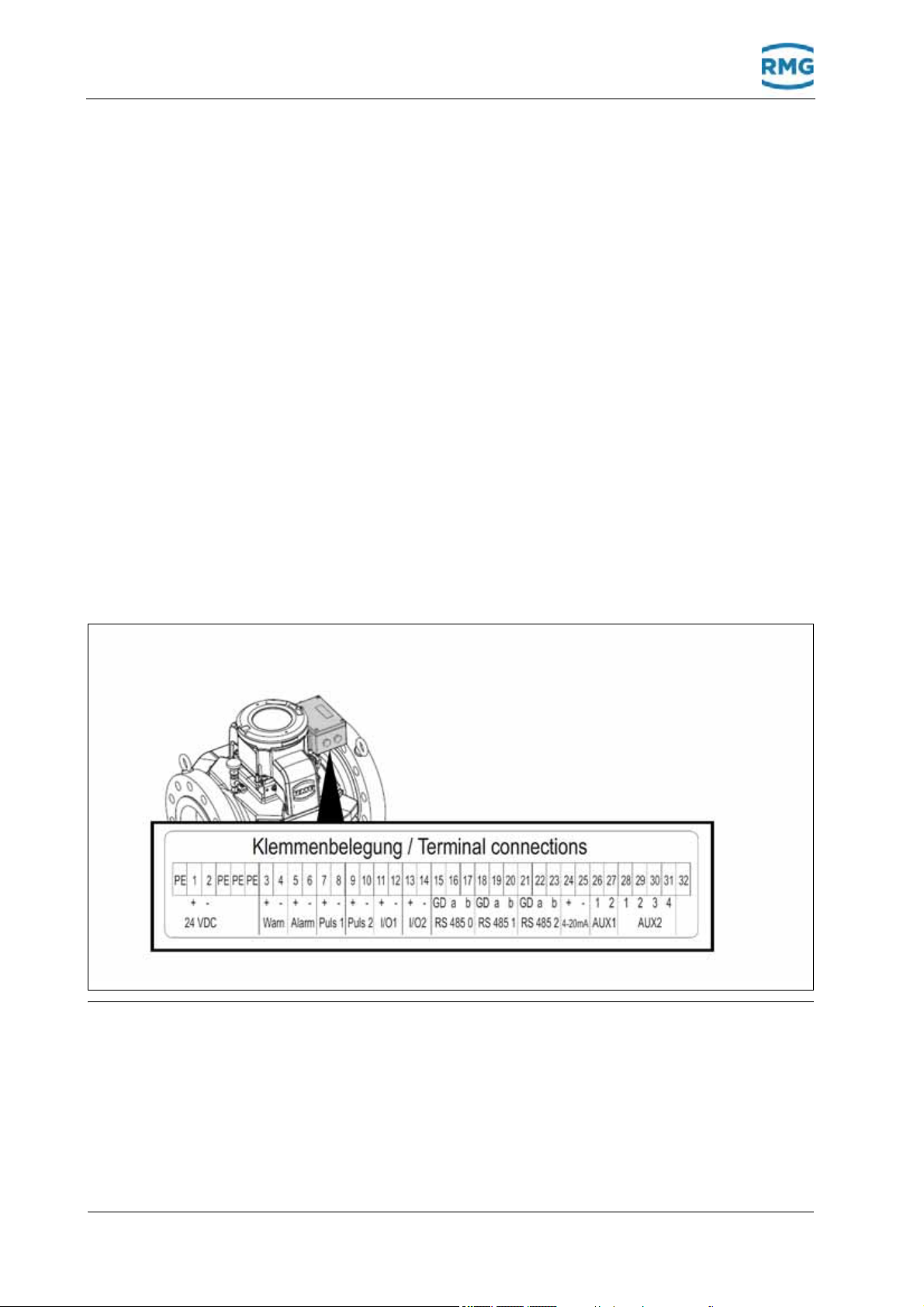
Fig. 2-1: Connection assignment on the terminal strip
10 Connect the computer to the terminals RS 485-0.
11 Allocate the terminal strips according to the applications.
Option: connect ERZ 2000 (-NG) to RS 485-1.
September, 4th 2018 Ultrasonic Flowmeter USM GT400 7
2 Brief instructions
2.3
Start Up
12 Supply the device with power supply (24 V DC) via the
system.
If the power LED illuminates green permanently, the device is
ready for operation.
If the alarm and warning LED do not flash, the device oper-
ates trouble-free.
Section 3.1, "Light emitting diodes" on page 14
The USM-GT-400 is supplied without connection box to the North
American region, the connection is made to cables that are led
through a flame arrester. The marking of the cable (numbers) is
(always) identical to the terminal assignment.
2.4
Earthing
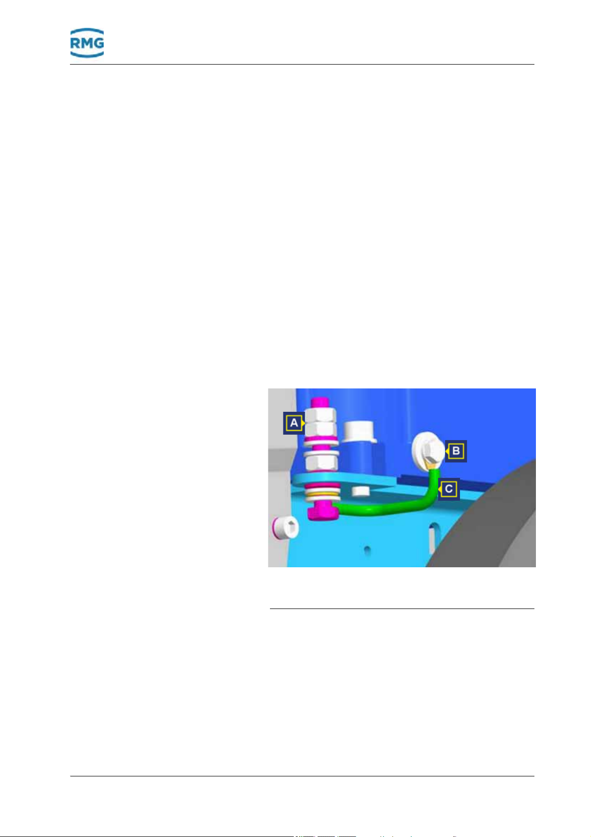
Fig. 2-2: Connect to earth - Ultrasonic gas meters DN150 (6")
and DN100 (4")
AEarthing screw M6 BEarthing screw M6
CEarthing cable

Fig. 2-3: Connect to earth - Ultrasonic gas meter
DN200 (8")
AEarthing screw M6 BEarthing screw M6
CEarthing cable
8Ultrasonic Flowmeter USM GT400 September, 4th 2018
2 Brief instructions
13 Connect the earthing cable according to the ultrasonic gas
meter version DN100 (4") to DN150 (6") or from DN200 (8").
2.5
Parameter setting
The device shall be supplied pre-assembled according to cus-
tomer agreement. Changes to the pre-assembly are more
extensive and are therefore not described in this brief instruction.
If this should be necessary, you will then find the description:
Section 10.1.3, "Calibration and Service Switch" on page 119

September, 4th 2018 Ultrasonic Flowmeter USM GT400 9
3 Device overview
3
Device overview
In this chapter you will receive information on the main compo-
nents of the ultrasonic gas meter and the arrangement of the
ultrasonic transducers in the housing of the ultrasonic gas meter.
Contents 3.
3.1 Main components ................................................ 9
3.2 Ultrasonic electronics ....................................... 11
3.3 Arrangement of the ultrasonic transducers .... 15
3.1
Main components
Fig. 3-1: Main components of the ultrasonic gas meter
ACovers of the transducer and
transducer lines
BCovers of the transducer lines
CUltrasonic electronics DLifting eyes
EJoining flanges FTransducer
GRetaining bolts
The ultrasonic gas meter consists of the following main
components:

10 Ultrasonic Flowmeter USM GT400 September, 4th 2018
3 Device overview
Covers of the transducers (A and B) The covers protect the connections and the lines of the transduc-
er (TD) against contamination and mechanical damage.
Ultrasonic electronics (C) The ultrasonic electronics is in a pressure tight, encapsulated
housing mounted on the ultrasonic gas meter. The ultrasonic
electronics evaluates the data recorded by the transducers. In
addition to the display, the parameters can be shown and evalu-
ated on a computer using the RMGViewUSM software.
Lifting eyes (D) The lifting eyes can be used to safely transport the device using
a suitable lifting gear.
Connection flange (E) The device is bolted onto the gas line using the connection
flanges.
Transducer (F) The transducers are installed in the housing of the ultrasonic gas
meter and are not visible once installed.
Retaining bolts (G) The retaining bolts are mounted when delivering the device. The
retaining bolts secure the product from tipping over or rolling
away. The bolts must be mounted to ensure for a safe installation
or de-installation.

September, 4th 2018 Ultrasonic Flowmeter USM GT400 11
3 Device overview
3.2
Ultrasonic electronics
Fig. 3-2: Ultrasonic electronics and display
AService and calibration switch BControl panel
CDisplay DMagnet for operation
ECover with viewing window FPressure tight housing
Device data (readings and parameters) can be set and evaluated
via the display and the operating elements.
Moreover, the device data (readings and parameters) can also be
shown, evaluated and set using the RMGViewUSM software.
Service and calibration switch (A) The service switch (right switch) is only for RMG service. The ser-
vice switch is, e.g., used to install new firmware.
The calibration switch (left switch) protects the parameters
against unauthorized changes. The device can be configured by
opening the calibration switch.
Control panel (B) The control field comprises buttons that are triggered by pressing
a button or magnetically. Parameters, readings, warning, alarm
and status messages are called up using the button.
Display (C) The display shows the readings, warning , alarm and status mes-
sages as well as the parameters.
Magnet for operation (D) The magnet is used to operate the control panel of the ultrasonic
electronics when the housing is closed. If the magnet is placed
above the symbol on the viewing window, this function is
activated.

12 Ultrasonic Flowmeter USM GT400 September, 4th 2018
3 Device overview
Cover with viewing window and
pressure tight housing (E and F)
The cover and the pressure tight housing encapsulate the ultra-
sonic electronics against the potentially explosive atmosphere.
During operation, information can be read through the viewing
window from the display and status indicators of the LEDs.
Electrical connection
(Terminal strip)
More information on the electrical connection can be found here:
Chapter 8.3, „Connecting the device electrically“ on page 84
Display screen
Fig. 3-3: Example for a possible display
First line Shows the name of the parameter (coordinates) called-up, e.g.,
p-maximum value (maximum pressure value).
Second line Shows the value of the parameter (coordinates) called-up, e.g.,
52.00 bar a.
Third line Shows the coordinate designation, e.g., A-06, thus column A, line
06.
The calibration switch is open. The value of the parameter can be
changed.
The calibration switch is closed. The value of the parameter can-
not be changed.
Forth line Shows the warning, alarm and status messages, e.g., -01 power
failure

September, 4th 2018 Ultrasonic Flowmeter USM GT400 13
3 Device overview
Buttons
When the cover is closed, the buttons can be operated through
the glass using the magnets supplied. The cover must not be
opened.
Change to the columns. Jump, e.g., from A to B and back again.
When holding for a longer time, you can change the columns by
quickly scrolling back.
Change or scroll forwards in the lines step by step, e.g., from A-
01 to A-02.
When holding for a longer time, you can change the lines quickly
scrolling forward.
Change or scroll back in the lines step by step, e.g., from A-01 to
A-02.
When holding for a longer time, you can change the lines with
quick return.
Enter values.
Reset button
The reset button (A) is for RMG service only. If the reset button is
pressed, the ultrasonic electronics is restarted.
Switches
Calibration switch (A): Activate to change parameters.
Service switch (B): For RMG service only. For installing a new
firmware.

14 Ultrasonic Flowmeter USM GT400 September, 4th 2018
3 Device overview
Light emitting diodes
Fig. 3-4: LEDs of the electronic ultrasonic electronics
AFlow BPower (supply voltage)
CAlarm DWarning
EReset FService (service switch state)
GCalibration (calibration switch
state)
HButton states
LED Illuminates con-
tinuously
flashing
Power Voltage supply is
switched on.
—
Flow Gas flow present. —
Alarm Alarm message is
stored.
Alarm is active.
Warning Warning message is
stored.
Warning is active.
Reset Reset is running. —
Calibration Calibration switch is
open.
—
Service Service switch is
open.
—
Control panel Panel is being
pressed.
—
September, 4th 2018 Ultrasonic Flowmeter USM GT400 15
3 Device overview
3.3
Arrangement of the ultrasonic trans-
ducers
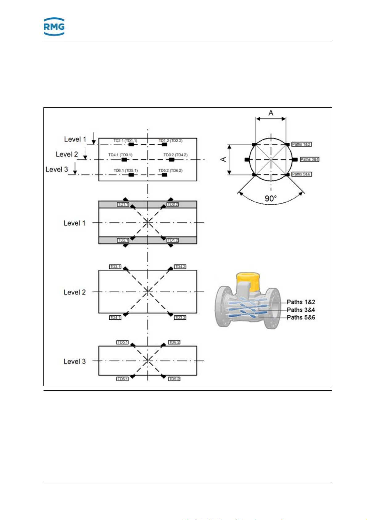
Fig. 3-5: Transducer paths and levels of the ultrasonic gas meter
The figure shows the arrangement of the transducers that are lo-
cated in the ultrasonic gas meter. The arrangement of the
transducers in the three levels is shown in three section
representations.
Four transducers are installed per level. The transducers form
two paths per level for the measurement.

16 Ultrasonic Flowmeter USM GT400 September, 4th 2018
3 Device overview
Other manuals for USM GT400
1
Table of contents
Other RMG Measuring Instrument manuals


