Robland T120 User manual

T120 & T110i 05-V0917 1
–Deutsch
–English
Contents
Contents 1
Ordering spare parts 3
Safety and maintenance instructions 3
User guide 4
Normal and prohibited use 6
Position operator at workstation 7
Noise and dust emission values 7
Application options 9
Types of tools 9
Technical data T-110i 10
General dimensions T-110i 10
Technical data T-120 S 11
Technical data T-120 L 11
Technical data T-120 P 12
General dimensions T-120 13
Transportation of the machine 14
Electrical connection 16
Power supply 16
Dust extraction 17
Operating and locking the sliding table on T110i 17
Starting up the machine 18
Adjustment of the spindle fence 19
Spindle fence protections 20
Removing the spindle fence guide 20
Using the ring guard fence 21
Moving the tenoning table 21
Clamping system 22
Spindle arbor lock 23
Installation of a feeder 24
Independent stops and programmable drawer 24
Changeable spindle (option) 26
Installation of tools 26
Maintenance 28
Problems and troubleshooting 28
Kickback of the workpiece 29
Position of the limit switches 30
Readjusting the engine brake 31
Calibration of the digital readout 31

204-V0917 T120 & T110i
–English
–Deutsch
Bestellung von Ersatzteile 36
Sicherheitsvorschriften 36
Gebrauchsanweisung 37
Bestimmungsgemäß Verwendung 39
Position-Bediener am Arbeitsplatz 40
Lärm und Staub Emissionswerte 41
Beabsichtigte Verwendung 42
Arten von Werkzeugen 43
Technische daten T-110 i 43
Allgemeiner Abmessungen T-110i 44
Technische daten T-120 S 44
Technische daten T-120 L 45
Technische daten T-120 P 46
Allgemeiner Abmessungen T-120 47
Transport und Inbetriebnahme 48
Anschluss an die Hausleitung 50
Netzanschluss 50
Starten der Maschine 51
Absauganlage für Holzstaub und Holzspäne 52
Bedienung und Sperrung von der Schiebetisch T110i 52
Einstellung Fräsanschlag 53
Schutz- und Andruckvorrichtung 54
Entfernung Frässchutz 54
Bogenfräsanschlag 55
Verschieben der Zapfenschneidetisch 56
Werkstück-Spannvorrichtung 56
Frässpindle-arretierung 57
Einbau einer Zuführung 58
Längen-Begrenzungs-Anschlage 58
Austauschbare Spindel (Option) 60
Aufspannen der Fräswerkzeuge 60
Wartung und Pflege der Maschine 62
Fehlersuche und Behebung 62
Rückschlag des Werkstück 63
Function der Endschaltern 64
Nachjustierung der Motorbremse 65
Einstellung Digital Wiedergabe 65

T120 & T110i 05-V0917 3
–Deutsch
–English
Ordering spare parts
Always mention the following items on your order:
- type of the machine
- serial number of the manual
- part number and quantity
- your references: contact name of consignee and address at place of destination.
For your safety and the operating reliability of the machine:
USE ROBLAND PARTS ONLY
Safety and maintenance instructions
Woodworking with machinery is a pleasant job that gives lots of satisfaction. Nevertheless, it requires
constant attention and care. Therefore, for your own safety, pay attention to the instructions
summarized in this chapter.
The machine can only be used safely when the operator strictly follows the operating and safety
instructions. It is essential to read this manual before using the machine to know how the machine
functions and what the limitations are.
Provide for sufficient space around the machine and a good lighting of the workshop.
When changing the tools or performing a maintenance job, the machine has to be disconnected from
the power supply.
Knives and tools which are not correctly sharpened or in a bad condition not only diminish the quality
of the work, but also increase the risk of accidents.
Always make sure that all necessary safety are fitted to the machine and that the machine is
connected to a dust extraction system.
Always wear suitable clothing. Loose or torn clothes are very dangerous while operating the machine.
Keep children away from the machine and the workshop.
Wearing of hearing protection is recommended to prevent noise from damaging your hearing.
When cutting narrow pieces always use a push stick. When damaged replace the push stick at once.
Always use jigs, templates and shaper tools adapted to the work carried out.
Read the recommendations to clean the machine carefully. Clean only when the machine is
disconnected from the power supply line.
It must be taken in account for the determination of the health risks that using, for example, MDF,
various types of impregnation agents, glues, synthetic resins, paints, varnish, abrasive paper and
other elements, which can have harmful effects, are added to the wood. Think of preservatives and
pesticides and certain microorganisms.
Make sure all periodic maintenance is done on time. These maintenances works should only be
carried out with the machine disconnected from the main power supply line thus rendering it
impossible to start the machine involuntary.
Test on a weekly basis the following electrical components: emergency stop buttons, the safety
switches and test if the machine can be started up with an open door.
Test on a weekly basis if the rundown time of the motor brake does not exceed 10 seconds.
Keep this manual where the operator may refer to whenever necessary. This manual must accompany
the machine when it is sold, rented or lent to a third party.
Attention!
Working with woodworking machines can be extremely dangerous if the safety instructions are
not followed.
Therefore use systematically the safety equipment provided on your machine.

404-V0917 T120 & T110i
–English
–Deutsch
User guide
The following recommendations for safe working procedures are given as an example, on top of all
information and characteristics of this machine.
- When working with the machine, safety equipment must be used.
- Nevertheless, the user must also follow the operating instructions to avoid accidents.
Training of the machine operators
It is essential that the machine operator gets enough training regarding operating and adjusting the
machine. In particular:
- the risks involved in working with the machine;
- the operating principles, the correct use and adjustments of the machine;
- the correct choice of the tool for each operation;
- the safe handling of the parts to be processed;
- the position of the hand in relation to the turning parts;
- storing workpieces safely before and after machining them.
Stability of the machine
In order to use the machine safely, it is essential to place it stable on the ground.
Adjustment and installation
- Disconnect the machine from its power supply for each adjustment.
- The recommendations of the manufacturer should be followed when adjusting and installing the
tools.
- The tools have to be suited to the machine in order to assure a safe and efficient usage.
- The tools have to be correctly sharpened and installed with tool holders that are carefully balanced.
Handling of tools
When touching the tool there is always the danger to get hurt by cutting edges.
- Be cautious when unpacking or packing, as well as handling.
- Do not touch tools at the cutting edges.
- Wear safety gloves when handling tools in your workshop.
- Always put the tools on a soft support.
- Transport clamping adaptors and tools only in a suitable packing.
Machine handling
- Choose for each action the most appropriate safety devices.
- Do not remove chippings, cuttings, dust and waste of wood or particle board by hand.
Installing tools
Special equipment, such as tool setting gauges, are to be used only when the machine isn't operating.
Table insert rings have to be used in order to reduce the space between the table and the spindle
shaft to a minimum.
Adjustment of the fences
Working with the spindle fences requires special attention:
- a false or integrated fence should be used to minimize the opening between the tools and the
fences
- a push stick should be used as often as possible
- a wood pusher should be used, together with protection, to push the piece manually
- long pieces need to be supported with roller supports
Direction of rotation and choice of speed
It is very important that the chosen tool turns in the right direction.
When the piece is presented, the operator must take care that the work piece is fed in the correct
direction at the correct chosen speed. The speed also has to be suited to the tool on the machine.
Functioning of the machine, choice of safety equipment and adjustments
Because of the various tasks that are carried out by various spindle shafts, spindle holders and cutter
blocks, different types of safety equipment have to be used. Every operation has to be examined
separately and the appropriate guarding has to be chosen. The minimal opening in the table also
depends on the type of cutter block, the diameter of the knives and the height which the cutter block is
adjusted in. In that way, the opening is as narrow as possible and the work piece no longer can flip

T120 & T110i 05-V0917 5
–Deutsch
–English
over and hit the knives.
Using a power feeder can prevent most serious accidents involving hands. Such feeders easily are
adjusted and adapted to the size of the pieces.
When no power feeder is used, the wood pushers have to be used, the horizontal and vertical springs
making a tunnel where the piece can slide in. This pusher, together with other safety equipment,
reduces the gap between the cutting tool and the guide fences.
Using the spindle fence when the total length of the machine has to be
machined
In most cases a straight guard fence is used. In this way the pieces can be guided in the angle made
by the table and the fence. The vertical and horizontal pushers can be placed in such a way that a
tunnel is formed in which the first piece can be pushed. The second piece is then used to push the
first, the final piece has to be pushed forward with a wood pusher.
Special blocks have to be used relative to the dimensions of the work piece.
When working thin panels, only the top of the spring has to be used, on condition the thickness
matches.
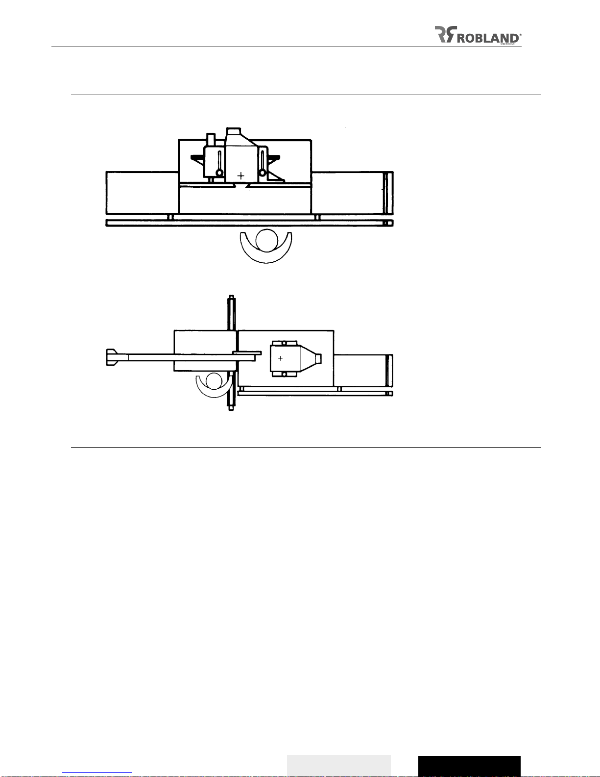
On a spindle-moulder, the distance between the extremities of the spindle guard fences must be large
enough to leave enough space for the cutter block. Thus the knives, the cutter block and the spindle
shaft may be exposed and the extremity of the piece may come in contact with the nose of the exit
guard fence.
These risks can be avoided by using a false fence between the spindle guard fences, thus limiting the
opening between them.
Using the spindle guard fence when only a part of the piece is machined
When using the spindle fence between 2 stops fixed onto the machine table or fences, only a part of
the work piece is machined. By doing so, the cutting tool starts machining the work piece in the full
section of the wood and doesn't start at the front, this way the cutting action is more gradual and less
severe, and the cutting action is stopped before the workpiece end is reached. This action is very
dangerous and needs special attention and care.
A stop solidly fixed at the front and back has to be used (see the example used further in this manual).
A piece may only be guided by hand when it is sufficiently large. In all other cases a gauge or a
support with protection has to be used in order to avoid serious accidents. By means of the gauge, the
piece can quickly and precisely be put in place and firmly be held there. A quick clamping system,
working with tumblers or cams, is the most practical to hold the piece. When front and backstops are
fixed to the spindle guard fence or to the table, a better control of the gauge is possible.
Working with the ring guard
When working with the ring guard, a support has to be used, unless a certain process doesn't allow
this, i.e. when the work piece is too large or too small, or when too difficult to machine it cannot be
held in the support without danger. The final shape is obtained by holding the gauge against a
guidance bearing which is fixed to the spindle while the piece is held against the tool. The gauge can
be part of the support.
Chamfering
When chamfer7ing a solid support or a tilt adjustable spindle, a guard fence has to be used. A wood-
pusher has to be used for the final part of the machining.
Working in the direction of the tools
It is extremely dangerous to work in the direction of the tools, as the operator cannot exert force to
resist the strong movement of the piece when the tool comes into contact. Working in the direction of
the tools is forbidden, even when a support is used.
Other machining
For other types of work, e.g. tenoning, special gauges or supports can be used in order to avoid
accidents.
The following safety accessories can be used to help the operator during his work:
- supports,
- wood pushers,
- power feeders,
- rollers,
- stops.
Reasons for tool rupture
Following reasons may lead to a tool rupture:

604-V0917 T120 & T110i
–English
–Deutsch
- grinding cracks or a change of the cutting geometry due to improper sharpening
- jerky movements of the work piece
- jamming of tool by waste piece
- overheating by friction due to slow feed rate or too low cutting depth, as well as due to dull cutting
edges
- too high feed rate
- too large cutting depth
- insufficient clamping of the tool
- vibration of the machine.
Operation
- Danger of injuries or crushing by the rotating tool
- Do not touch the rotating tool
- Do not slow dawn the tool by lateral pressure against the body
- Do not work without the necessary safety guard.
Normal and prohibited use
With the T120 and the T110i spindle-moulder the operator can mould and form straight and curved
pieces, and almost any task in woodworking can be executed in massive wood, wood-based panels
and certain plastics.
It is strictly forbidden to process ferrous and non-ferrous materials. It is also forbidden to make
changes to the machine in order to execute other tasks than those described above.
Moulder-shaper
The shaper assembly is assigned to the following tasks and equipped with protective devices. Other
tasks than listed below are therefore prohibited.
NORMAL USE
- mould and form straight and curved pieces on the vertical spindle;
- shaping of curved work pieces using a ring guard fence;
- tenoning and panel edge shaping using corresponding safety devices.
PROHIBITED USE
The following tasks are prohibited on the moulder-shaper unit:
- down-cut shaping, i.e. when feed and tool rotation direction is the same;
- slotting with saw blades;
- using tool diameters that are not adapted to the spindle by using reducing sleeves;
- using larger tool diameters and higher speeds than shown in the diameter-speed diagram;
- the use of ferrous and non-ferrous.
REMAINING RISKS
Spindle shapers are one of the main causes of injuries in woodworking. Nearly all accidents result in
hand injuries. Due to contact with the rotating tool when the work piece is fed by hand, a kickback
occurs.
The main danger areas on the shaper-moulder are:
- the moving machine and tool parts;
- the kickback area.
Always use the appropriate protection devices and observe the specific regulations for accident
prevention.
Despite the use of specific protection devices and the application of the hygiene and safety
instructions, some risks remain when working with the moulder-shaper:
- risk of accidents in the insecure area of the tools;
- risk of wounding while replacing tools;
- risk of wounding by the piece of wood itself;
- crushing of the fingers;
- risk of jamming of the hand in the machine, when using a removable pusher;
- risk of back kicked pieces of wood;
- health risk through prolonged inhalation of particles, especially oak, beach or exotic sorts of wood
- deafness through prolonged exposition to noise.

T120 & T110i 05-V0917 7
–Deutsch
–English
Position operator at workstation
A) Moulding (T120 en T110i):
B) Tenoning:
Noise and dust emission values
Most workshops are likely to have a noise exposure over 85 db. That means noise controls should
be introduced by repositioning noise sources such as machines, exhaust systems, radio, etc...
Reduction of noise
The state of the tools is important to minimize the noise. The material and positioning of the
protector must be so that they reduce the noise level. The use of personal protective equipment
should not be an alternative to what is mentioned above.
If noise levels are still too high after you have done what you can to reduce the noise at the source,
you need to provide ear protection and ensure that operators use it. Hearing protection only provide
the right level of protection when worn properly and for the whole time, the users are exposed to
high noise levels.
Hearing protection should at least reach the volume to reduce the ear below 85 db. However, you
should not try to reduce the level at the ear, under 70 db, thus, difficulties with communication and
operators cannot hear warning signals.
Acoustic levels
The values given are the output levels, these are not necessarily the levels on which the operator
can work safely. Although there is a link between the output values and the safe working levels, it
cannot be used in a reliable way to determine whether supplementary measures should be taken.

804-V0917 T120 & T110i
–English
–Deutsch
Dust emission limit values
The harmful effects of wood dust when inhaled are known. This is especially true for the substance
produced in the processing of carcinogenic hardwoods, such as oak or beech. In addition, the
inhalation of wood dust can cause asthma and allergic reactions to the skin during prolonged
contact.
For (hard) wood dust, a limit value in the air of 2 mg/m³ is applied at the workplace as an average at
8 hours of exposure. When acquiring new woodworking machines, it is assumed that no more dust
is released in operations than a maximum of 1 mg/m³ (emission value).
When ventilation air is recirculated, the air may never contain more wood dust than 10% of the limit
value after filtering. For the concentration of wood dust in return air this is therefore 0.2 mg/m³.
This means that we must first take the source measures (avoid dust emissions) and also take other
measures, such as the shielding of workers and the extraction of the wood dust.
In principle, a minimum air flow of 20 m/s must be ensured in the suction pipe. In certain cases (e.g.
high machining volumes, high feed speeds or wet chips), there may be higher air speeds (up to 28
m/s) required for effective suction. However, suction speeds above 28 m/s are generally not
technically feasible.
Personal Protective Equipment
If exposure to wood dust cannot be avoided, the employer must provide the employees with
personal breath protection and ensure that they are actually used. They must be sufficiently present
in the workplace. Of course, these must meet a number of requirements, such as fitness for the
purpose, comfort, hygiene, etc.
Wood dust, however, causes other risks. In addition to a layer of dirt that precipitates in the
workshop, the wood dust can block machines, bearings and motors and hinder the overall progress
of work.
Recommended measures for the handling of wood dust are:
Choose (wood) material that causes as little substance as possible;
Choose a working method that distributes less dust;
Choose tools with a good (point) suction;
Care for maintenance of suction equipment and tools;
Clean the workplace regularly by sucking, so do not swipe;
Use for removing wood dust an industrial vacuum cleaner and not compressed air.
Provide information and instruction on wood dust and preventive measures
Work station
under load
Level continuous
acoustic pressure
as
per index A dB(A)
Level acoustic
power
dB(A) (MW)
Max value acoustic
pressure as per
index C
(instantaneous) dB
Moulding
84
97 (3,2)
< 130
Tenoning
86
97 (5)
<130

T120 & T110i 05-V0917 9
–Deutsch
–English
Application options
The T120 with fixed or interchangeable vertical spindle and T110i with tilting vertical spindle under
angle (-5° /+ 45°).allow the user profiling, shaping and tenoning of wood.
All the tasks of woodworking, the furniture factory and shaping can be carried out, but only in solid
wood, wood-based panels and certain plastics.
Safe use requires special knowledge and skill, but accidents cannot be completely avoided. There are
obvious solutions to reduce human failure or at least the consequences of human failure. However,
none of these solutions offers warranty. Both man and machine are not 100% reliable or safe to get. If
we want to improve security, we need to find it elsewhere. Although human failure is often a direct
cause of many accidents, more factors play a role. We call these underlying causes 'latent factors'. It
is these factors that determine whether the circumstances are unfavorable or not.
It is therefore strongly advised to use all the protections that are mounted on the machine, and to read
carefully the advices given in this guide.
When using electrical tools, basic safety precautions should always be followed to reduce the risk of
fire, electric shock and personal injury.
Take notice of the given warnings and advices. They serve your safety and the good working order of
the machine.
This operating instruction manual is intended for all persons who carry-out work with this tool. It must
be read before using and it always must be easily accessible for all persons.
Attention!
Please note that in the versions T120S and T120L cannot be adapted to a T120P - chariot-version,
i.e. the version with table. Because of the different adjustments that must be made, it is impossible to
assemble the table on the basic versions S and L. On the other hand, the S version of the T120
mouldling machine can be adjusted to a L-version, by mounting 2 table extensions and a telescopic
extension at the front of the machine.
Types of tools
Cutter blocks and the tool holders with interchangeable blades are frequently used when moulding.
The cutter blocks can be made in one piece, the cutting part being fitted in a body of hard steel, mostly
chromium steel. The tool holders consist of the part on which the knives are fitted mechanically. Their
cutting part is made out of hard metal (HSS) or calcium-carbide (K), as is the case for the cutter
blocks.
Important
For each tool and for each diameter, the correct speed must be chosen.

10 04-V0917 T120 & T110i
–English
–Deutsch
Technical data T-110i
Table dimensions
1000 x 520 mm
Table height
920 mm
Diameter spindle
30 mm (option : 50mm/40mm/1 ¼”)
Spindle length
150 mm
Spindle stroke
140 mm
Speed spindle
3000/4500/6000/7000/10000 RPM
Standard motor
7,5pk (5,5kW S1) - option 10pk S1 (7,5kW S1)
Option motor up/down & front/back
0,1kW
Max. diameter depth table opening
260 x 60 mm
Nett weight
530 kg
Tilting
-5° / +45°
length chariot
1400 mm
Dust extraction
2x 120 mm
Robland RAL colour
RAL7021 & RAL7035
Standard equipment
- Spindle: 30 mm
- Set of tools
- Fences in MDF
- 7,5 HP motor
Options
- 10 HP motor
- Fences in aluminum / Aigner integral fence
- Elektric connection for feeder
- Elektric up/down, tilting
General dimensions T-110i

T120 & T110i 05-V0917 11
–Deutsch
–English
Technical data T-120 S
Table dimensions
1200 x 705 mm
Table height
920 mm
Diameter fixed spindle
50 mm–(option: 30 mm / 40 mm / 1¼”)
Spindle length
180 mm
Spindle stroke
205 mm
Speed spindle
3000/4500/6000/7000/10000 RPM
Standard spindle motor power
7,5pk (5,5kW S1) - option 10pk (7,5kW S1)
Option motor up/down
0,1kW
Max. diameter and height table opening
320 x 95 mm
Net weight
560 kg
Dust extraction
2x 120mm
Robland RAL colour
RAL7021 & RAL7035
Standard equipment
- Fixed spindle: 50 mm
- Set of tools
- Fences in MDF
- 7,5 HP motor
Options
- Changeable spindles, diameter on request
- 10 HP motor
- Fences in aluminium / Aigner integral fence
- Electrical connection for feeder
Technical data T-120 L
Table dimensions
1200 x 705 mm
Table height
920 mm
Diameter spindle
50 mm –(option: 30 mm / 40 mm / 1¼”)
Diameter fixed spindle
180 mm
Spindle stroke
205 mm
Speed spindle
3000/4500/6000/7000/10000 RPM
Standard spindle motor power
7,5pk (5,5kW S1) - option 10pk (7,5kW S1)
Option motor up/down
0,1kW
Max. diameter and height table opening
320 x 95 mm
Total length with extensions
2600 mm
Total length width telescopic extension
1315 mm
length telescopic extension front
2050mm
Net weight
655 kg
Dust extraction
2x 120mm
Robland RAL colour
RAL7021 & RAL7035
Standard equipment
- Fixed spindle: 50 mm
- Set of tools
- Fences in MDF
- 7,5 HP motor
Options
- Changeable spindles, diameter on request
- 10 HP motor
- Fences in aluminium / Aigner integral fence
- Electric connection for feeder

12 04-V0917 T120 & T110i
–English
–Deutsch
Technical data T-120 P
Table dimensions
1200 x 705 mm
Dimension carriage
770 x 500 mm
Stroke carriage
1050 mm
Table height
920 mm
Diameter fixed spindle
50 mm–(option: 30 mm / 40 mm / 1¼”)
Length spindle
180 mm
Stroke spindle
205 mm
Speed spindle
3000/4500/6000/7000/10000 RPM
Max. admitted speed tenoning
3000 RPM
Standard motor power
7,5HP (5,5kW S1) - option 10HP (7,5kW S1)
Option motor up/down
0,1kW
Max. diameter and depth table opening
320 x 95 mm
Total length with table extension
2700 mm
Max. diameter tool in tenoning guard
360 mm
Net weight
1000 kg
Dust extraction
2x 120mm
Robland RAL colour
RAL7021 & RAL7035
Standard equipment
- Fixed spindle: 50 mm
- Set of tools
- Fence in MDF
- 7,5 HP motor
- Tenoning unit
Options
- Changeable spindles, diameter on request
- 10 HP motor
- Fences in aluminium / Aigner integral fence
- Electric connection for feeder
Attention
For tenoning, the speed is limited to 3000 rpm, for the spindle moulder there is a choice of speeds.

T120 & T110i 05-V0917 13
–Deutsch
–English
General dimensions T-120

14 04-V0917 T120 & T110i
–English
–Deutsch
Transportation of the machine
Depending on the method of transport or shipping, you will retrieve the machine in a crate or on transport
blocks protected by a plastic foil.
Remove the sides of the crate or cover.
The machine can be lifted with a small crane, or by sliding the forks of a forklift into the opening in the
frame (Fig 1), but severe shocks should be avoided.
Attention!
When uploading the machine with a forklift, please raise the spindle arbor completely.
The spindle must protrude at least 10 cm at the top when the forks of the forklift are
pushed into the opening and the forks of the forklift must go so far as to support the
front and back of the frame).
Place the machine on a concrete base, and level the machine in both directions.
The packing itself, made of fireboard and wooden beams, can easily be recycled. Take the
sides off the crates and remove the cardboard and parts fastened to the bottom of the crate. For
will pick up, the assembled machine is mounted securely on transport blocks.
The table surface and all exposed parts are covered with a protective plastic film.
Avoid any impact when unloading the machine and never pull the worktable.
Use a wooden ramp made of thick board and wooden beams and secure the ramp to the pallet
to avoid slipping of the ramp. Never try the machine on rollers when it's on an incline. Once the
machine is on ground level, move it with a pallet jack or forklift.
Take the machine off the pallet by means of lever bands (Fig 2), always ensure that these are
not able to shift or loosen. Keep in mind the balance during the lifting, possibly provide a
counterweight (extra attention T120 P version).
Attention!
Make sure the loading capacity is sufficient. Place the lever bands in a way they don't put
pressure on the tables. Lift the machine a few centimeters to remove the bottom of the
crate.
Start up
Make sure the machine was not damaged during transportation or whilst uploading. Position the
machine in a stable position on solid underground and make sure there is enough space around
the machine to use safely.
It is necessary to ensure that all operating instruments are easily accessible, and that there is
enough space around the machine to be able to use them in all safety.
After that, the 4 height control bolts (Fig. 3) must be tightened and the machine must be set in
the 2 directions. Preferably let the machine rest on rubber plates, which then serve as shock
absorbers.
The machine is constructed in a way that it is not necessary to attach the machine to the
ground, but if you wish to do so, it is possible by means of a set screws.

T120 & T110i 05-V0917 15
–Deutsch
–English
Fig.1a Fig.1b
Fig.2 Fig.3

16 04-V0917 T120 & T110i
–English
–Deutsch
Electrical connection
The electrical connection has to be carried out by a qualified electrician who is able to calculate the
required wire section and amperage of the fuses.
- confirm that the main voltage of your machine corresponds with the voltage in your workshop;
- the open the electrical components box at the back of the machine (fig 3);
- connect the 3 phases to the terminals marked L1, L2, L3 (fig 4);
- if there is a neutral conductor (blue) it has to be connected to the terminal N;
- connect the earth (green + yellow) to the terminal marked with the earth symbol;
- make sure the spindle runs free prior to starting up the motor.
Attention
- First, make sure that the spindle runs free and all necessary protective equipment is in place before
starting up.
- Should the direction of rotation be incorrect, the wires L1 and L2 must be exchanged. For safety,
this must be carried out without tools on the spindle. Check the direction of rotation of the motor. This
test should be carried out on the spindle-motor at 3000 RPM. The direction of rotation must be, seen
from above, anticlockwise.
Power supply
Electric potential motor spindle: 7,5pK (5,5kW S1) - option 10pK (7,5kW S1)
Electric potential motor up/down –front/rear : 0,1kW
Wire section connection wires: 2,5 mm2
Nominal current: 11A (5,5 kW S1), 15A (7,5 kW S1)
Internal fuse head current: 3x230V –25A of 3x400V –16A
Connection: 3x230V + earth of 3x400V + earth
Frequency: 50 Hz
Abb.3

T120 & T110i 05-V0917 17
–Deutsch
–English
Dust extraction
For your health and to avoid risk of fire and dust explosion, the machine should be connected to a dust
extraction system. When using the machine, the dust extraction system must always be turned on.
The machines are provided with a 120mm exhaust section on the spindle protection (above the working
table) and a 120mm disposal opening on the frame (under working table). It is advisable to connect the
disposal pipes as close as possible to the exhaust openings of the machine to direct the dust and the chips
in a joint pipe (160mm) to the dust extraction/disposal system.
We recommend an extraction speed of 25m/s. The flow rate of the air in the joint pipe (160mm) must
be higher than 1800 m3/h. To prevent wood waste in the piping, a sufficiently high transmission speed
must be guaranteed throughout the system. A minimal airspeed of about 20 meters per second for wood
dust, 25 m/s for dry shavings and 28 m/s for wet shavings is sufficient in most cases. Suction speeds
above 28 m/s are generally not technically feasible.
Operating and locking the sliding table
on T110i
The sliding table can be blocked in 2 positions by means of a latch system. This is used when workpieces
to be modified are loaded against the parallel conductor. The latch system is located on the front of the
sliding table. Pull the knob (1) in your direction and turn to the right to free the sliding table. Pull the sliding
table backwards. At the end pull the button and turn to the left to block the sliding table.
By the repeated movements of the sliding table it is possible that the bearing cage between the two profiles
moves a little. This is also noticeable by a reduced travel distance of the sliding table. To proceed working
and restore the normal travel distance of the sliding table, you can adjust the position of the bearing cage.
Push the table with a few short, light pushes, back against the rubber end buffers.
Cleaning and maintaining the sliding table
It is important to remove on a regular basis the sawdust and other dust particles that get collected between
the trolley and the bearings cage. Push the sliding table to the end to get a better reach to the bearings
cage and gliding tracks. Lubricant, such as WD40, is extremely suitable for lubricating the rails and
provides an extra guarantee for good use and function.

18 04-V0917 T120 & T110i
–English
–Deutsch
Starting up the machine
- Turn on the main switch (fig 4.1), which can be padlocked, on “1” to put the machine under tension.
- Make sure the brake release switch (fig 7.2) is in position ”0”.
- When the yellow indicator lights up (fig 7.3) the machine cannot be started up.
- Put the star-delta switch (fig 5.4) on “star” and push the start button (fig 5.5). The motor starts up in
“star”, but must be switched to “delta” after about 10 seconds.
- The motor can be switched off by the “stop” button (fig 5.6 / fig 6.6 / fig 8.6) or by the “emergency
stop” button (fig 5.7 / fig 6.7 / fig 8.7).
Fig.4 Fig.5 Fig.6 (T110i)
Attention
- When the machine is stopped, the motor automatically brakes.
- It is not possible to start the machine while the access door is opened or when the brake release
switch (fig 7.2) is on “1” and the yellow indicator (fig 7.3) lights up.
- The control lights (fig 7.9) indicate the speed of the spindle.
- The switches (fig.6.9 / fig.8.10) determines electric up or down movement of the spindle (option) and
functions only when the main motor is switched off.
- Switches (fig 6.8) move the spindle under angle.
- When using automatic star delta (fig 7.8) the direction of the rotation is determined by the switch
(fig.6,5/fig.8,5).
- To prevent the machine from turning the wrong direction there is an additional security feature:
should the machine turn in the opposite direction a yellow indicator lights up (fig 5.11 / fig 7.11).
Fig.7 Fig.8 (T120)

T120 & T110i 05-V0917 19
–Deutsch
–English
Adjustment of the spindle fence
Basic version
- The body of the spindle fence is attached to the table with 2 bars (fig 9.1).
- The infeed fence can be arranged micrometric relative to the body of the fence by a screw
(fig 9.3).
- the position is locked by a knob (fig 9.2) on the side of the spindle fence.
Fig. 9
PRO version
- The body of the spindle fence is located on a guide plate and moves on linear guides.
- This plate is attached to the table by 2 locking pins (fig 10.1).
- The spindle fence is moved by using a hand-wheel (fig 10.2).
- Use the other hand-wheel to control the infeed fence (fig 10.3).
- Use the locking screw (fig 10.4) to lock the infeed guide in position.
- The body of the spindle fence is attached to the table with a bar (fig 10.5).
Fig.10

20 04-V0917 T120 & T110i
–English
–Deutsch
Spindle fence protections
Adjustments:
- Adjust the fences as close as possible to the tools and adjust the horizontal wood-pusher (fig 10.2) according to
the width of the piece of wood. Adjust the vertical wood-pusher (fig 10.3) according to the height of the piece of
wood that is machined, but make sure the wood is placed as close as possible to the fences.
- When the protection is placed correctly, the wood-pushers exert enough pressure and the wood can be put put
against the fences while it is supported between the clamps.
- It is advised to use a push-stick while working with the spindle protection.
- If only part of the wood is machined (see “operating instructions”) it is easier to push the piece of wood against
the stop when the horizontal wood-pusher screen is turned away.
- To remove the entire system from the vertical axle, it is needed to remove the knob..
Fig.11
Removing the spindle fence guide
- When the machine is equipped with a lift arm (option) the spindle fence guide can be removed easily.
- Move the protection forward on the guide plate and place the infeed guide backwards as far as possible. Proceed to
slide the superstructure forward to disassemble the guides.
Warning!
- When the machine is not equipped with a lift-arm (option), the removal of the spindle fence guide (weighting nearly
100 kg / 220 lb) is at your own risk and it is necessary to take adequate safety measures.
Important
- Start by unscrewing the 2 barring pens (fig 11.2) that hold the guiding plate when the lift arm is mounted.
- Then proceed to screw the lift arm (fig 11.2) onto the lifting block (fig 11.3).
- Once the spindle fence is completely lifted, the whole system can be pivoted away.
- To post the system back, just push the spindle fence back into place. Repair points are provided on the guiding
plate.
This manual suits for next models
1
Table of contents
Languages:
Other Robland Industrial Equipment manuals