Roc Hobby DPROC001RS User manual

Length:530.5mm
Width: 258mm
Height:270mm
Wheelbase: 324mm
Ground clearance: 39.5mm
Approach angle: 58°
Departure angle: 22°
Breakover angle: 36°
PARAMETERS
1:6 1941
mb scaler
PNP version does not include transmitter and receiver .Manuel d’utilisation
Instruction Manual
Bedienungsanleitung
操作手册


Safety precautions
Radio system manual
ESC system manual
Vehicle setup
Wiper installation,Lifting and retracting the windshield
Opening the hood
Setting up the canvas bracket
Operating the vehicle
General list of accessories (I)
General list of accessories (II)
3
4
8
12
13
13
14
14
53
54
55
55
56
57
58
59
60
61
62
63
TABLE OF CONTENTS
02
.......................................................................
.......................................................................
.............................................................................
........................................................................
....................................
............................................................
.....................................................................
Car body assembly 1
Car body assembly 2
Car body assembly 3
Chassis exploded-view
.....................................................................
.....................................................................
.....................................................................
...................................................................
.............................................................
............................................................
General list of accessories (III) 64
............................................................
Front and rear wheel assembly
Front axle assembly
Oil shock absorbers assembly
Main gear box assembly
Rear axle assembly
Transmission gear box assembly
...........................................................
............................................................
..................................................................
.......................................................................
.......................................................................
.........................................................
....................................................................
EN

Introduction
This model is a sophisticated hobby product and not a toy. It must be operated using caution and common sense. Beginners
should seek the advice of experienced hobbyists to ensure that the model is properly built, run and maintained.
Some mechanical knowledge and ability is expected of the hobbyist, as failure to operate and maintain this model may result
in property damage, serious injury or even death.
This model is not intended for use by children without proper adult supervision.
Please follow the instructions and all posted warnings within this manual in order to properly assemble, setup, use and main-
tain this model.
Safety, precautions and warnings
CE compliance information for the european union
This model is controlled by a radio signal that is subject to interference from many sources outside your
control. This interference can cause momentary loss of control so it is necessary to always keep a safe
distance in all directions around your model, as this will help to avoid collisions or injury.
Always operate your model in an open area away from cars, traffic, or people.
•
Never operate your model with low transmitter batteries.
•
Carefully follow the directions and warnings for this product and any optional support equipments (chargers, rechargeable
battery packs, etc.) that you use.
•
Keep all parts, chemical solvents, oils and electrical components out of the reach of children.
•
Moisture may cause damage to electronic components over time. Ensure that all electronic components, even waterproof
components, are fully dried out after every run. Never run your model in salt-water.
•
The associated regulatory agencies of the following countries recognize the noted certifications for this product as
authorized for sale and use.
Declaration of Conformity
Products: 2.4GHz Controller
Equipment Class: 2
The objects of declaration described above are in
conformity with the requirements of the specifications
listed below.
Item Name : 2.4GHz Controller
The RED Directive 2014/53/EU
EN 60950-1:2006 + A11:2009 + A1:2010 + A12:2011 + A2:2013
EN 300 328 V2.1.1:2016
EN 301 489-1 V2.1.1:2017
EN 301 489-17 V3.1.1:2017
UK DE DK BG SE GZ ES NL SK HU RO FR PT
FI EE LV LT PL AT CY SI GR MT IT IE LU
SAFETY PRECAUTIONS
03
EN

RADIO SYSTEM INSTRUCTION MANUAL
This product is not a toy! (14+) Recommended for ages 14 and up. Adult supervision
required for ages under 18 years old. Contains small parts, keep out of reach of children
3 years of age and younger.
Please read this manual carefully prior to using.We are not responsible for any intention-
al damage or improper use.lf you require any additional information or have any
quesions adout he product or its use,please contact us via(www.rochobby.com).
Your model is equipped with an advanced 2.4GHz radio system. This system uses a frequency hopping spread
spectrum technology that allows for minimal interference operation.
Prior to operating your new radio system, please take a few minutes to familiarize yourself with the various
features and functionality of the system by reading this instruction manual thoroughly.
Statement - This device complies with Part 15 of the FCC Rules.
Operation is subject to the following two conditions:
FCC ID 2ARE7-91805
This equipment complies with FCC radiation exposure limits set forth for an uncontrolled environment. And should be operat-
ed with minimum distance of 20 cm between the antenna & your body.
RF Exposure Warning:
1. this device may not cause harmful interference, and.
2. this device may not cause harmful interference, and.including interference that may cause undesired operation.
Changes or modifications not expressly approved by the party responsible for compliance could void the user’s authority to
operate the equipment.
AA x4
4CH
Pistol grip
2.4 GHz
Configuration
Model TX
Frequency Band
Channels
Output Power
Frequency Range 2405.0~2478.0
0.0054Watts
Battery
Dimensions
Length(mm)
Height(mm)
Width(mm)
155.10
193.70
81.30
MADE IN CHINA
Specifications
04
AUX 3 2 1
34mm
18mm
LED>
4CH 2.4GHz
WATERPROOF RECEIVER
SW>
155.1mm
81.3mm
193.7mm
13.5 mm
EN

RADIO SYSTEM INSTRUCTION MANUAL
Warranty
The ROCHOBBY 4 channel radio system is guaranteed to be free from defects in materials and workmanship within 30 days
of the purchase of the product. If the product has been mishandled, abused, used incorrectly or used for an application other
than its intended purpose- ROCHOBBY is not liable for any loss or damage, whether direct or indirect, incidental or conse-
quential, or from any special situatuon, arising from the use, misuse, or abuse of this product.
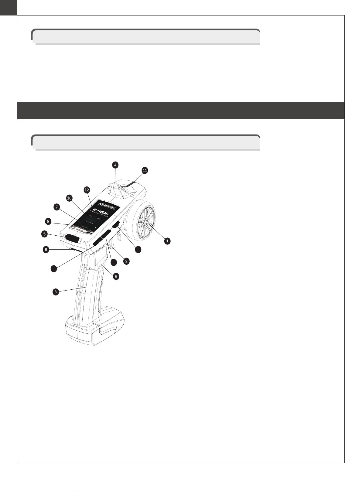
3. Hand Grip: For holding the transmitter.
Steering Wheel: Controls the steering function of the
model.
1.
Throttle Trigger: Controls forward / reverse / brake
motion(designed to be operated with index finger).
2.
Antenna:Transmits signal to the receiver located in the
vehicle.
4.
Battery compartment: Houses [4] AA batteries9.
10. Channel 3 key.
11. LED.
Channel 4 key.15.
7. CH3-EPA+/-
8. CH4-EPA+/-
12. Reverse:
1:Turn and hold the steering wheel to the left or right
while simultaneously pressing the REV button. An
audible note is emitted and the steering channel will be
reversed.
2:Push or pull the throttle trigger to its maximum
position while simultaneously pressing the REV button.
An audible note is emitted and the throttle channel will
be reversed.
3:Press CH3 and REV simultaneously. An audible
note is emitted and CH3 will be reversed.
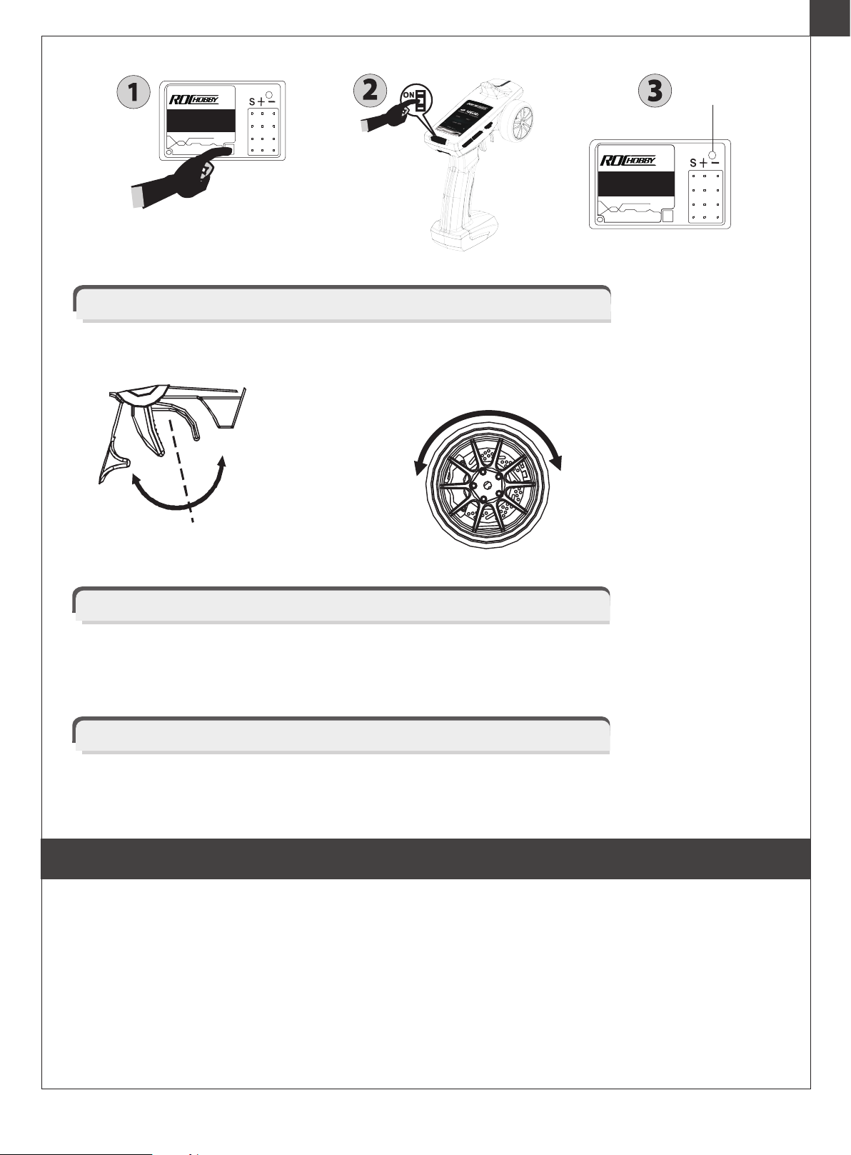
13. ST DR/ST TRIM: Please turn the wheel to left or right
with Max angle, and press ST-TRIM+ or ST-TRIM-,
then adjust the angle of ST.
14. TH DR/ TH TRIM: Please pull or push the throttle to its
maximum position, then press the TH-TRIM+ or
TH-TRIM - button to adjust the maximum output of the
throttle channel.
When adjusting the trim, the transmitter will emit an
audible note for every click of trim. When the trim has
been centered, the transmitter will emit two audible
notes.
When adjusting the dual rates, an audible note will be
emitted with every click of the dual rate. Two notes
signify the dual rate is at its maximum or minimum.
6. Handle release latch.
Power switch:Turns the transmitter ON / OFF.5.
Function operation introduction
05
13
14
15
EN

1.Pull the handle release latch.
2.Pull back on the handle to release the handle from the
transmitter itself.
3.To replace the handle, pull back on the handle release
latch and push the handle back onto the transmitter.
This transmitter accepts alkaline or NiMH AA batteries. There is a built in low voltage warning where when the
voltage is lower than 4.5V +/- 0.2, the buzzer will sound continuously and the LED will flash. This is to remind the
user to change the batteries for fresh units.
3. Reinstall the battery cover.
Remove the battery cover from the transmitter.1.
Insert four new AA batteries according to the polari-
ty markings on the battery holder.
2.
Warning: do not attempt to charge non-rechargeable batteries,
you may cause an explosion.
Warning: please don't reserve the battery,or it will burn out
the PCB.
06
Removing or replacing the handle
Battery installation
EN

AUX 3 2 1
Channel connection
Channel 1: Controlled by the wheel, connect to a servo for steering.
•
Channel 2: Controlled by the trigger, connect to the ESC or a servo for throttle/brake.
•
Channel 3: Controlled by the adjustment knob (0-100%) for optional use. This port can also be used to connect a transpon-
der device used in racing.
•
AUX (Channel 4): Controlled by button (ON/OFF) for optional use. This port is most commonly used for LED light kits. Use
this port to connect an external battery for use with gas powered vehicles.
•
Pairing the transmitter & receiver
Note: Radio systems installed in RTRs have already been paired. Only when installing a new transmitter
or receiver is the above process necessary.
2. Turn on the transmitter.
3. When the LED on the receiver becomes solid,the binding process is completed.
1. Turn on the receiver power. Press the SW switch.The receiver’s LED should start flashing.
Receiver installation & connection
Receiver
CH1
CH2
CH3
CH4
Throttle Servo
Channel 3 Servo
Channel 4 Servo
Connect to
receiver battery
Y-line
07
Ensure there are no kinks in the antenna or antenna tube.
•
Never fold the end of the antenna over the tube, this will reduce the operating range of the system and damage the antenna.
•
Ensure the receiver is mounted securely or padded against hard impacts.
•
To achieve full operating range with your radio system it is critical that the receiver antenna be undamaged and
installed properly. It should be installed with as much of the antenna as possible in a vertical position. The end of
the antenna should be contained inside an antenna tube. When installing:
Installation
EN

Operation
A. THROTTLE TRIGGER B. STEERING WHEEL
1. Push the trigger
forward to slow down
or brake.
2. Pull the trigger backward
to accelerate.
Forward/
Speed increase
Brake/Speed
decrease Reverse
Neutral
Left
Neutral
Right
08
Fail safe function setting
Turn on the TX, keep the throttle at the fail safe point, press the SW button on the receiver for about 2 seconds. The LED
should flash for 5 seconds, release the SW button and TH trigger, then turn off the TX.
General care
1. Always use clean, dry cloth or soft bristle brush to clean your equipment.
2. Never use chemical cleansers, as these could damage the sensitive electronics and plastics.
ESC SYSTEM MANUAL
Features
1. Waterproof and dust-proof for all weather operations.
2. Compact sizing with built in capacitor module.
3. Automatic throttle range calibration.
4. Multiple protections: Low voltage cut-off protection for Lipo or NiMH battery / Over-heat protection / Throttle signal loss
protection.
5. Easily programmed with the jumpers.
AUX 3 2 1
LED>
4CH 2.4GHz
WATERPROOF RECEIVER
SW>
AUX 3 2 1
LED
LED>
4CH 2.4GHz
WATERPROOF
RECEIVER
SW>
EN

09
Specifications
ESC setup
Motor Limit
Cont. / Burst Current
Input
Forward: 60A / 360A Backward: 30A / 180A
2-3S Lipo, 5-9 Cells NiMH
Vehicles applicable
Resistance
Built-in BEC
Dimension&Weight
1:10 on-road, off-road Buggy, Truggy, SCT 1:10 Crawlers, Tank &Boat
2S Lipo or 5-6 cells NiMH
3S Lipo or 7-9 cells NiMH
540 or 550 size motor ≥ 8T or RPM <45000 @7.2V
540 or 550 size motor ≥13T or RPM <30000 @7.2V
Fwd: 0.0008 Ohm, Bwd: 0.0016 Ohm
3A/6V (Switch mode BEC)
36*30*18, 40g
Model WP-1060-BRUSHED
1. Connect the ESC, motor, receiver, battery and servo according to the following diagram
Ensure that the + and - wires of the ESC are connected to the battery pack.
The control cable of the ESC is connected to the throttle channel of the ESC (Usually CH2).
The motor + and motor - cables are connected to the motor in any order, if the motor runs in reverse, reverse the cables.
Attention: The incorrect polarity will damage the ESC immediately.
Please set the “D/R”, “EPA” and “ATL” to 100% for throttle channel (for transmitter without LCD, please turn the
knobs to the maximum value), and set the “TRIM” of the throttle channel to 0 (for transmitter without LCD, please
turn the TRIM knob to its neutral position).
For Futaba TM and the similar transmitters, the direction of throttle channel shall be set to “REV”, while other
radio systems shall be set to “NOR”. The “Fail Save” function of the radio system is strongly recommended to be
activated. Please make sure that the motor can be stopped when the “Fail Save” happens.
2. Set the Transmitter
Servo
To “Throttle” channel
Motor + (Yellow)
Batter + (Red)
Batter + (Black)
Brushed Motor
Motor - (Blue)
Receiver
Switch
LED
EN

10
3.
Throttle Range Setting (Throttle Range Calibration)
In order to make the ESC match the throttle range of different transmitters, the calibrationof the ESC is necessary. To
calibrate the ESC, please turn on the transmitter, keep throttle stick at its neutral position, wait for 3 seconds to let the ESC
execute self-test and automatic throttle calibration. When the ESC is ready to run, a long beep sound is emitted from the
motor.
Note: Please calibrate the throttle range again when using a new transmitter or changing the settings of the neutral position
of throttle channel, D/R, ATV, ATL or EPA parameters,otherwise the ESC may not work properly.
Audible warnings and LED status
Throttle stick position
Set the ESC
Top point of backward directionTop point of forward directionNeutral point
When the throttle stick is in neutral range, red LED
is off
Forward, brake or reverse at partial throttle, red
LED blinks
Forward, brake or reverse at full throttle, red LED is
solid
1 short beep: The battery is NiMH/NiCd
2 short beeps: The battery is 2S Lipo
3 short beeps: The battery is 3S Lipo
4 short beeps: The battery is 4S Lipo
1 long beep: Self-test and throttle calibration is
OK, the ESC is ready to run
Beep meaning LED Status
•
•
•
•
•
•
•
•
1. The ESC is programmed by the jumpers (Tweezers are is recommended to plug and unplug the jumper).
MODE
BATT
F/B/R F/B/R F/B/R
Lipo NiMH
F/B/R:Forward, brake and reverse
F/B/R:Forward with brake
F/B/R:Forward and reverse (Crawler mode)
D:WP-1060-BRUSHED
EN

11
3. Throttle signal loss protection: The ESC will cut off the output power if the throttle signal has been lost for 0.1 second. The
“Fail Save” function of the radio system is strongly recommended to be activated.
2. Over-heat protection: When the internal temperature of the ESC is higher than 100 Celsius degree or 212 Fahrenheit
degree for 5 seconds, the ESC will reduce and cut off the output power.
When the car stops, the red LED blinks to indicate the over-heat protection has been activated. If the ESC cools down to
80 Celsius degree (176 Fahrenheit degree) the output power is recovered to normal state.
Troubleshooting
Protection functions
1. Low voltage Cut-off (LVC) protection: If the voltage of battery pack is lower than the threshold for 2 seconds, the ESC will
enter the protection mode.
When the car stops, the red LED blinks to indicate the low voltage cut-off protection has been activated.
Table A:LVC protection for WP-1060-BRUSHED
2S Lipo 3S Lipo
Output reduces 50% at 6.5V Output cuts
off at 6.0V, cannot be recovered.
Output reduces 50% at 9.75V Output cuts
off at 9.0V, cannot be recovered.
Fault Possible Reason Drivetrain fault Solution
After power on, motor doesn’t
function, no sound is emitted and
LED is off.
After power on, motor doesn’t
function; red LED blinks.
The model reverses when throttle
is given ( the motor runs in the
opposite direction).
The ESC isn’t receiving enough
voltage or the connection between
the battery pack and ESC is broken.
Throttle signal is abnormal.
Switch is damaged. Replace the switch.
Automatic throttle calibration has
failed.
Check the battery wires connection or
replace the defective connectors.
Check the throttle wire connection;
make sure it is plugged into the throttle
channel of the receiver.
Set the “TRIM” of throttle channel to 0
or turn the knob to its neutral position.
Swap two wire connections between
the ESC and the motor.
The wire connections between ESC
and the motor need to be changed.
The model only reverses.
The motor doesn’t work, but the
LED in the ESC works normally.
Replace the motor.
Reset the direction of throttle
channel from original “NOR” to “REV”,
or from original “REV” to “NOR”.
The direction of throttle channel is not
correct.
The connections between motor and
ESC are broken.
Motor is damaged.
Check the connections and replace
the defective connectors.
The model does not reverse.
Check the jumper and plug it to the
correct position.
The jumper position is wrong.
Set the “TRIM” of throttle channel to 0
or turn the knob to its neutral position.
The neutral point of throttle channel
is changed or drifted.
EN

Connecting the battery
VEHICLE SETUP
12
Fault Possible Reason Drivetrain fault Solution
The motor suddenly stops running
while in working state.
The throttle signal is lost.
Motor is cogging when accelerated
quickly.
Check the drivetrain of the vehicle.
Check the transmitter and the receiver.
Check the throttle wire connection.
Check the settings.
Set D/R, EPA, ATL to 100% or turn the
knobs to maximum value.
Set TRIM to 0 or turn the knob to its
neutral position.
Replace the battery pack, or cool
down the ESC.
Use battery with better discharge
ability.
The battery has limited discharge
ability.
The transmitter is improperly setup.
Low voltage cut-off protection or
Over-heat cut-off protection has
been activated.
Motor RPM is too high, the gear ratio
is too aggressive.
Use motor with lower RPM, or use
smaller pinion to get softer gear ratio.
Something wrong in the driving
system of the car.
The model cannot reach its
maximum speed and the red LED
does not become solid at full
throttle.
STEP 2: Lift the vehicle body and place the brace rod
between the chassis and body.
STEP 3: Place the battery in the battery box then
connect the battery plug (T-plug or XT60 plug).
STEP 1: Release the two body clips.
EN

13
WIPER INSTALLATION,LIFTING AND RETRACTING THE WINDSHIELD
Step1: Please install the wipers in the diagram2 position.
Step2: Lift the windshield assembly.
Step3: Gently press on the center of the windshield, the
component will bend and lock onto the hood.
Pressing on the center of the windshield again will allow
for the windshield to be retracted.
Install the windshield wipers by referencing the diagram
below.
OPENING THE HOOD
Step1: Lift the hood up.
Step2: Move the hood strut onto the engine compartment to keep the hood in place.
EN

OPERATING THE VEHICLE
Step 1: Turn on the transmitter- the status LED will turn blue and an audible tone will be emitted.
Step 2: Power on the vehicle by turning on the ESC switch. The front lights will illuminate and an audible sound will be emitted.
After the receiver confirms that a transmitter signal has been received, it will emit another audible tone.
The above guidelines, must be installed the battery.
This vehicle is equipped with a slipper. If the vehicle loses transmission traction, please check the slipper tension and replace
if necessary.
Spare parts C1067 SLIPPER PAD.
14
SETTING UP THE CANVAS BRACKET
Step1: Pull out the canvas bracket.
Step2: Insert the canvas bracket into the bracket mount.
EN

TABLE OF CONTENTS
15
Sicherheitshinweise
Bedienungsanleitung Fernsteuerung
Bedienungsanleitung Fahrtenregler (ESC)
Setup Fahrzeug
Demontage der Windschutzscheibe
Öffnen der Motorhaube
Montage des Verdeckgestänges
Betrieb des Fahrzeuges
Teileliste (I)
Teileliste (II)
16
17
21
25
26
26
27
27
53
54
55
55
56
57
58
59
60
61
65
66
Explosionszeichnung der Karosserie 1
Explosionszeichnung der Karosserie 2
Explosionszeichnung Karosserie 3
Explosionzeichnung des Chassis
Explosionszeichnung der Vorder- und Hinterräder
Explosionszeichnung der Vorderachse
Explosionszeichnung der Stoßdämpfer
Explosionszeichnung des Getriebes
Explosionszeichnung der Hinterachse
Explosionszeichnung der Getriebebox / Achsabtrieb
.......................................................................
...............................................
...........................................................................
...................................................................
......................................................
..........................................................
..................................................................
....................................................
....................................................
.......................................................
.........................................................
...............................................................................
...............................................................................
Teileliste (III) 67
...............................................................................
........................................
...................................................
......................................................
....................................................
....................................................
......................................
......................................................
DE

Introduction
This model is a sophisticated hobby product and not a toy. It must be operated using caution and common sense. Beginners
should seek the advice of experienced hobbyists to ensure that the model is properly built, run and maintained.
Some mechanical knowledge and ability is expected of the hobbyist, as failure to operate and maintain this model may result
in property damage, serious injury or even death.
This model is not intended for use by children without proper adult supervision.
Please follow the instructions and all posted warnings within this manual in order to properly assemble, setup, use and main-
tain this model.
Safety, precautions and warnings
CE compliance information for the european union
This model is controlled by a radio signal that is subject to interference from many sources outside your
control. This interference can cause momentary loss of control so it is necessary to always keep a safe
distance in all directions around your model, as this will help to avoid collisions or injury.
Always operate your model in an open area away from cars, traffic, or people.
•
Never operate your model with low transmitter batteries.
•
Carefully follow the directions and warnings for this product and any optional support equipments (chargers, rechargeable
battery packs, etc.) that you use.
•
Keep all parts, chemical solvents, oils and electrical components out of the reach of children.
•
Moisture may cause damage to electronic components over time. Ensure that all electronic components, even waterproof
components, are fully dried out after every run. Never run your model in salt-water.
•
The associated regulatory agencies of the following countries recognize the noted certifications for this product as
authorized for sale and use.
Declaration of Conformity
Products: 2.4GHz Controller
Equipment Class: 2
The objects of declaration described above are in
conformity with the requirements of the specifications
listed below.
Item Name : 2.4GHz Controller
The RED Directive 2014/53/EU
EN 60950-1:2006 + A11:2009 + A1:2010 + A12:2011 + A2:2013
EN 300 328 V2.1.1:2016
EN 301 489-1 V2.1.1:2017
EN 301 489-17 V3.1.1:2017
UK DE DK BG SE GZ ES NL SK HU RO FR PT
FI EE LV LT PL AT CY SI GR MT IT IE LU
SICHERHEITSHINWEISE
16
DE

BEDIENUNGSANLEITUNG FERNSTEUERUNG
This product is not a toy! (14+) Recommended for ages 14 and up. Adult supervision
required for ages under 18 years old. Contains small parts, keep out of reach of children
3 years of age and younger.
Please read this manual carefully prior to using.We are not responsible for any intention-
al damage or improper use.lf you require any additional information or have any
quesions adout he product or its use,please contact us via(www.rochobby.com).
Your model is equipped with an advanced 2.4GHz radio system. This system uses a frequency hopping spread
spectrum technology that allows for minimal interference operation.
Prior to operating your new radio system, please take a few minutes to familiarize yourself with the various
features and functionality of the system by reading this instruction manual thoroughly.
Statement - This device complies with Part 15 of the FCC Rules.
Operation is subject to the following two conditions:
FCC ID 2ARE7-91805
This equipment complies with FCC radiation exposure limits set forth for an uncontrolled environment. And should be operat-
ed with minimum distance of 20 cm between the antenna & your body.
RF Exposure Warning:
1. this device may not cause harmful interference, and.
2. this device may not cause harmful interference, and.including interference that may cause undesired operation.
Changes or modifications not expressly approved by the party responsible for compliance could void the user’s authority to
operate the equipment.
AA x4
4CH
Pistolensender
2.4 GHz
Konfiguration
Modell TX
Frequenzband
Kanäle
Ausgangsleistung
Bandbreite 2405.0~2478.0
0.0054Watts
Batterien
Abmessungen
Länge(mm)
Höhe(mm)
Breite(mm)
155.10
193.70
81.30
MADE IN CHINA
Spezifikationen
17
AUX 3 2 1
34mm
18mm
LED>
4CH 2.4GHz
WATERPROOF RECEIVER
SW>
155.1mm
81.3mm
193.7mm
13.5 mm
DE

BEDIENUNGSANLEITUNG FERNSTEUERUNG
Warranty
The ROCHOBBY 4 channel radio system is guaranteed to be free from defects in materials and workmanship within 30 days
of the purchase of the product. If the product has been mishandled, abused, used incorrectly or used for an application other
than its intended purpose- ROCHOBBY is not liable for any loss or damage, whether direct or indirect, incidental or conse-
quential, or from any special situatuon, arising from the use, misuse, or abuse of this product.
3. Senderhandgriff.
Lenkrad: Kontrolliert die links / recht Steuerfunktion
des Modells.
1.
Gashebel: Kontrolliert die vorwärts / rückwärts /Brems-
funktion. (Wird mit dem Zeigefinger bedient).
2.
Senderantenne: Die Antenne überträgt das Fernsteuer-
signal zu dem im Fahrzeug montierten Empfänger.
4.
Batteriefach: Für vier (4) AA Batterien.9.
10. Kanal 3 Taster.
11. LED.
Channel 4 key.15.
7. CH3-EPA+/-
8. CH4-EPA+/-
12. Reversieren (Umdrehen) der Fernsteuerfunktionen
1:Halten Sie das ganz nach links oder rechts einges-
chlagende Lenkrad und drücken gleichzeitig den REV
Button. Sie hören dann einen Ton und der Steuerkanal
ist reversiert.
2:Drücken oder ziehen Sie den Gashebel bitte ganz
zum Anschlag und drücken gleichzeitig den REV
Button. Sie hören dann einen Ton und der Gaskanal ist
reversiert.
3:Drücken Sie den Kanal 3 Taster und drücken
gleichzeitig den REV Button. Sie hören dann einen Ton
und der Kanal 3 ist reversiert.
13. ST DR/ST TRIM: Einstellen des maximalen Lenkaus-
chlages Drehen sie das Lenkrad zum maximalen
Ausschlag und stellen dann mit Druck auf die Tasten
ST-TRIM+ oder ST-TRIM- den maximalen Lenkauss-
chlag der Vorderachse ein.
14. DR/ TH TRIM: Drücken oder ziehen Sie den Gashebel
auf die maximale Position und drücken dann den
TH-TRIM+ oder
TH-TRIM -Button um die maximale Leistung des
Gaskanals einzustellen.
Bei dem Einstellen der Trimmfunktionen hören Sie für
jeden Klick einen Quittungston. Steht die Trimmung in
der Mitte hören Sie zwei Töne.
Bei dem Einstellen der Dual Ratefunktion hören Sie für
jeden Klick einen Quittungston. Befindet sich diese
Position auf Minimum oder Maximum hören Sie zwei
Töne.
6. Hebel zum lösen des Griffes.
owerschalter: Schaltet die Fernsteuerung Ein (ON) und
Aus (OFF)
5.
Die Funktionen im Überblick
18
13
14
15
DE

Die Fernsteuerung ist für den Betrieb mit Alkaline Batterien oder NIMH Akkus der Größe AA ausgelegt.
Die eingebaute Unterspannungswarnung wird aktiv wenn die Spannung unter 4,5V +/- 0,2 fällt. Zur Erinnerung,
dass die Akkus geladen oder Batterien gewechselt werden müssen ertönt ein Piepton und die LED blinkt.
19
Entfernen des Handgriffes
Einsetzen der Batterien in die Fernsteuerung.
1. Drücken Sie die Öffnungslasche.
2. Ziehen Sie den Griff von dem Oberteil der Fernsteuer-
ung nach hinten.
3. Um den Griff wieder einzusetzen drücken Sie bitte
erneut die Öffnungslasche runter und schieben den Griff
wieder in das Oberteil der Fensteuerung.
1. Nehmen Sie den den Batteriefachdeckel vom Sender ab.
2. Setzen Sie vier (4) neue AA Batterien polrichtig in die
Fernsteuerung ein und achten dabei auf die Plus (+) und
Minus (-) Markierungen im Deckel.
3. Setzen Sie den Batteriefachdeckel wieder auf.
Warnung: Versuchen Sie niemals nicht aufladbare Battereien
aufzuladen, es besteht dabei akute Explosionsgefahr!
Warnung: Bitte reservieren Sie den Akku nicht, da sonst die
Platine durchbrennt.
(Note to FMS: The yellow mark says reserve, the correct
english word should be reverse.)
DE
Table of contents
Languages:
Other Roc Hobby Motorized Toy Car manuals

Roc Hobby
Roc Hobby SCALER MB 1941 User manual

Roc Hobby
Roc Hobby 1:12 TYPE82 KUBELWAGEN User manual

Roc Hobby
Roc Hobby 1:18 Fire Horse User manual

Roc Hobby
Roc Hobby ROC11242RTRCE User manual

Roc Hobby
Roc Hobby 11241 User manual

Roc Hobby
Roc Hobby 1:10 Atlas 4x4 User manual

Roc Hobby
Roc Hobby 1:18 Fire Horse User manual
Popular Motorized Toy Car manuals by other brands

Kogan
Kogan KARCTTRAILA manual

Associated Electrics
Associated Electrics SC10GT Manual & catalog

Traxxas
Traxxas STAMPEDE 4x4 67014-4 Assembly manual

Walthers
Walthers SceneMaster 949-11001 manual

REVELL
REVELL Corvette C6 Convertible Assembly manual

RC4WD
RC4WD TRAIL FINDER 2 CHEVROLET K10 SCOTTSDALE owner's manual