Roc Hobby 1:18 Fire Horse User manual

INSTRUCTION MANUAL
1:18 Fire Horse
We,
Phone:0769-86976655
Web:www.rochobby.com
declare under our responsibility that the product:
Type of Equipment: Driving System & 2.4GHz Control System
Brand Name: ROCHOBBY
Compatiable for cars: 1:18 Land Cruiser 80
EN 301 489-1 V2.2.3
EN 301 489-17 V3.2.4
EN 300 328 V2.2.2
EN 62479:2010
EN 62368-1:2014+A11:2017
IEC 62321-2:2013, IEC 62321-1:2013, IEC 62321-3-1:2013,
IEC 62321-5:2013, IEC 62321-4:2013, IEC 62321-7-2:2017,
IEC 62321-7-1:2015, IEC 62321-6:2015
ETSI EN 301 489-1 V2.1.1
ETSI EN 301 489-17 V3.1.1
EN 55032:2015
EN 610003-2: 2014, EN 61000-3-3: 2013
EN 55035:2017
Equipment Model: 11802 ROC004RTR
EN
Declaration of Conformity (DoC)
MADE IN CHINA
to which this declaration relates is in conformity with the essential requirements and other relevant
requirements of the Directive 2014/53/EU, EMC Directive 2014/30/EU, EMC Directive 2014/53/EU, FCC
Indentifier N4ZMG400 , EU RoHS Directive 2011/65/EU and Council Directive 2014/30/EU. The product is in
conformity with following standards and/or other normative documents:
Add:Room701,Block B, Luo Tian Community
Xiangshan Road142,Songgang Street,Shenzhen
Baoan District China

[1] 方向手轮,左右各 35 度(CH1) [10] 方向舵量调节旋钮(ST.D/R)
[2] 油门扣机,前 25 度后 12.5 度(CH2) [11] 油门舵量调节旋钮(TH.D/R)
[3] 按键开关(CH4)[ 按键功能为翻转式 ] [12] 拨码开关(切换电调的工作模式)
[4] 三档拨动开关(CH3) [13] 油门倒置开关(TH.REV)
[5] 挂绳孔 [14] 状态指示灯绿色 LED(G.LED)
[6] 手柄,4*AAA 电池仓 [15] 对码按键(BIND)
[7] 方向倒置开关(ST.REV) [16] 方向微调旋钮(ST.TRIM)
[8] 电源指示灯红色 LED(R.LED) [17] 油门微调旋钮(TH.TRIM)
[9] 电调电池电量显示双色灯(RX.BATT) [18] 电源开关
发射机概览
产品介绍
CN
ROCHOBBY全新攀爬车1:18赤兔Fire Horse
静态模型级别的全比例攀爬车,从车身准确线条,驾驶舱内饰、中控台、座椅、脚踏板、等比例备胎、散热
格栅、进气管等静态细节,到仿真伞齿驱动车轴、转向联动的方向灯组等功能细节。
不仅有漂亮的外观,作为迷你硬派越野攀爬车, 1:18赤兔亦有硬派底盘与悬吊。铝合金大梁确保即便在崎
岖地形中车架依旧保持良好的刚性。多连杆悬吊与止推杆设计有效精准舵机动作。超高扭力的齿轮箱与尼龙传动
轴将动力传递到车轴,再通过抓地力强的夹胎式软胎传递至地面。此外,宽大的车身设计能有效降低整车的重心
、增加行驶的稳定性。车架全封闭式设计,可以保证车辆涉水行驶。
1:18赤兔使用 ROCHOBBY一贯的防溅水电子系统,即独立舵机、二合一接收与电调、 050 大扭力电机、
7.4V 380毫安时锂电池,可以在任何天气和地形下行走。续航力长达30分钟!
ROCHOBBY 1:18赤兔,一款你不能错过的性价比优越的越野攀爬车!
[1] [12]
[2] [13]
[3] [14]
[4] [15]
[5] [16]
[6] [17]
[7] [18]
[8] [19]
[9] [20]
[10] [21]
[11] [22]
接收机概览
发射机电池安装
CN
CH1 通道接口 接收机天线
CH3 通道接口 LED 指示灯
CH4 通道接口 电池线“-”
左转灯接口 电池线“+”
右转灯接口 马达线 “M-”
前大灯接口 马达线 “M+”
后尾灯接口 电源开关线
氛围灯接口 贴纸
车顶灯接口 通道接口 “S ”端
车灯接口“-”端 通道接口“+”端
车灯接口“+”端 通道接口“-”端
电池类型使用:AAA电池
1. 打开电池仓盖。
2. 将4颗电量充足的AAA电池装入电池仓内,确保电池上的金属端子与
电池仓内的金属端子接触。
3. 盖好电池仓盖。
低电量报警:当电量低于4.2v时,面板上的G.LED慢闪报警提示。
注:注:安装电池时,请留意电池正负极,避免安装错误。(如右图所示)
请按照以下步骤安装发射机电池:
1 2

警告
开机操作
CN
本产品非玩具级别,不适合14岁以下的儿童操作使用。未成年人应在有经验的成年人陪同下操作
使用。
请使用原厂部件更换损坏的部件。特别注意所有车辆接线的正负极。
只能使用2节锂聚合物电池。不要过度充电或过度放电,以免电池泄露或损坏产生火灾隐患。如
果电池在充电过程中温度过热,请立即停止充电,并将电池与充电器断开。请勿在无人看管的情
况下给电池充电。
如果您不确定如何安全地进行充电,请向经验丰富的遥控模型产品玩家寻求建议。不要让孩子在
没有成人监督的情况下给电池充电。
由于电机在使用过程中会发热,两次操作中要留出大约10-15分钟的时间冷却电机,以延长产品
的使用寿命。
务必选择合适的环境操作遥控模型,所选环境需远离电缆、无线电塔、深水及不稳定地形。 本品
操作者对其行为全权负责。的环境中,请确保将电子部件完全晾干以后再使用。
确保每次操作前检查车辆的无线接收范围,以防止无线信号丢失或受干扰。
在您的能力范围内操作此产品。在任何时候,如果车辆操作有危险,则绝对不值得冒险。
通电方式:务必先开遥控器再将车子通电。断电方式:务必先将车子断电再关遥控器。以上顺序如逆
转,则可能引起遥控模型失控, 导致人身伤害或财产损失。
遥控器电池低电时,不要操作模型车,以免造成失控。
模型产品.上的塑胶件容易因极冷或极热气候出现变形或损坏的状况。所以请将模型产品存放在气
候受控的室温环境中,切勿靠近任何热源,如烤箱或加热器等。
切勿更改接收机天线的长度,以免影响无线电系统的接收范围。
仅使用厂家指定的电池。
请勿打开、拆卸或自行维修电池。
请勿挤压、刺穿或接触电池的金属端子。
请勿将电池置于高温环境或液体中。
请注意防止电池跌落、碰撞或振动。
请将电池存放在干燥阴凉的环境中。
如果电池损坏,请立即停止使用。
1. 检查系统状态,确保:
• 电池电量充足且安装正确。
2. 将开关拨到【ON】 位置,R.LED灯常亮。
3. 连接接收机电源。
• 为保障模型及人员安全,
使用时请先打开发射机再给接收机上电
•
•
此时系统已启动,请谨慎操作,
否则可能导致产品损坏或人员伤亡。
警告
为了您的安全请将发射机开关和油门
打到安全位置。
LED指示
对码
摇杆校准
CN
发射机和接收机在出厂前已对码成功。
该功能可以用于方向手轮和油门扳机的中位角度修正。
发射机在出厂前已校准完成,如需要重新校准,请按照一下步骤进行:
如需更换其他发射机或接收机,请按如下步骤进行对码:
1. R.LED: 红色电源指示灯;
2. G.LED: 绿色状态指示灯;
3. Car Battery:电调电池电量显示双色灯
• 电量高时,D3绿色常亮
• 电量中时,D3橙色常亮
• 电量低时,D3红色常亮
• 电量无时,D3红色慢闪
• 接收机掉码时,双色灯全灭
1. 将发射机按住对码键开机进入对码状态,此时G.LED快闪;
• 进入对码状态后松开“BIND”键
2. 接收机上电等待1秒没有连接将自动进入对码;
3. 对码成功后,接收机及发射机指示灯常亮;
注:对码时请先将发射机进入对码状态,再将接收机进入对码状态。
1. 同步将手轮顺时针打到最大、扣机往前推到底并开机,进入校准模式功能;
• R.LED和G.LED二闪一灭
• Car Battery双色灯黄色常亮
2. 手轮校准:操作手轮顺时针和逆时针转到最大最小;
• R.LED灭
• Car Battery双色灯红色常亮
3. 扣机校准:往前往后推到最大最小;
• G.LED灭
• Car Battery双色灯绿色常亮
4. 手轮扣机均校准通过
• Car Battery 显示灯均灭
5. 校准完成后按“BIND”键退出并保存数据。
3 4

关机
通道说明
通道反向
微调
舵量调节
模式切换
CN
警告
关闭时,请务必先关闭接收机电源,再
关闭发射机,否则可能导致模型损坏、
人员受伤。
1. 断开接收机电源。
2. 将开关拨到 【OFF】 位置,使发射机关闭。
该发射机共输出4个通道,分配如下:
• CH1:方向手轮
• CH2:油门扣机
• CH3:三档开关
• CH4:按键开关
注: CH4按键开机默认输出1000us,
按压操作一下通道值翻转一次,
数值在1000us/2000us之间互相
切换。
该功能用于调整舵机或马达的动作方向。
旋钮ST.REV/TH.REV分别为CH1、CH2通道反向按键,开关上拨表示反向,下拨表示正常。
ST.TRIM为CH1方向微调,可复用为CH3微调;
TH.TRIM为CH2油门微调,可复用为CH4微调;
调节范围:-120us-+120us;
ST.TRIM/TH.TRIM:逆时针调节,增大微调值,最大为120us;
ST.TRIM/TH.TRIM:顺时针调节,减少微调值,最小为-120us。
ST.D/R 为CH1方向舵量调节,可复用为CH3舵量调节;
TH.D/R 为CH2油门舵量调节,可复用为CH4舵量调节;
调节范围:0-120%;
ST.D/R:逆时针调节,增加舵量,最大为120%
ST.D/R:顺时针调节,减小舵量最小为0%。
TH.D/R:逆时针调节,增加舵量,最大为120%
TH.D/R:顺时针调节,减小舵量最小为0%。
此功能用于将ST.TRIM及ST.D/R旋钮复用于CH3、CH4通道
功能设置:
正常开机状态下快速短按两下对码按键(BIND)(1S 内)即可循环切换模式一、二,开机默认为模式一。
失控保护
初学者模式
电调参数设置
CN
功能设置:
模式一:R.LED常亮,G.LED不亮,ST.TRIM为CH1微调,ST.D/R为CH1舵量调节;TH.TRIM为CH2油门
微调,TH.D/R为CH2油门舵量调节;
模式二:R.LED和G.LED交替闪烁,ST.TRIM为CH3微调,ST.D/R为CH3舵量调节;TH.TRIM为CH4微调,
TH.D/R为CH4舵量调节。
初学者模式比较适合入门级玩家,通过对油门幅度的控制来提高操作的安全性。
初学者模式模式油门输出仅为50% ,即 CH2通道范围默认为1250~1500~1750us。
功能设置:
1. 按住CH4按键,同时方向手轮逆时针打到底
2. 维持以上动作同时开机
以上步骤可用于切换初学者模式和正常模式。
注:出厂默认为正常模式,开机时G.LED灯二闪一灭持续3S,代表此次进入初学者模式。
此功能用于当接收机无法正常收到发射机的信号时,对应通道舵机移动至预先设定的位置,保护模型和操
作人员的安全。
发射机开机正常通讯状态下,将需要设置的通道保持在需要设定的失控保护值位置保持不动,同时长按
对码键(BIND)3S,G.LED闪烁2S表示设置成功,即接收机无法接收信号后,将按照设定的失控值输出。
注:失控保护出厂默认无任何设置,无设置时失控接收机无有效信号输出。
拨码开关标识
发射机上的拨码开关用于设置电调参数,即拨码开关位于不同位置对应参数值不同。
5 6

CN
设置方法:
该电调有三个参数项可以设置,分别是“运行模式(Running Mode)”、“电池类型(Battery Type)”、
“拖刹力度(Drag Brake)”。遥控器面板上有一列编号为1 2 3 4的拨码开关,通过上下拨动可以实现对上述参数项的
设置,具体操作如下:
当遥控器面板上编号为1的拨码开关位于下侧时,表示运行模式设置为前进后退带刹车(FWD/REV/BRK)。
当遥控器面板上编号为1的拨码开关位于上侧时,表示运行模式设置为直接正反转(FWD/REV)。
当遥控器面板上编号为2的拨码开关位于下侧时,表示电池类型设置为锂电池(Lipo)。
当遥控器面板上编号为2的拨码开关位于上侧时,表示电池类型设置为镍氢(NiMH)。
当遥控器面板上编号为3的拨码开关位于下侧,编号为4的拨码开关也位于下侧时,表示拖刹力度设置为0%。
当遥控器面板上编号为3的拨码开关位于下侧,编号为4的拨码开关位于上侧时,表示拖刹力度设置为50%。
当遥控器面板上编号为3的拨码开关位于上侧,编号为4的拨码开关位于下侧时,表示拖刹力度设置为75%。
当遥控器面板上编号为3的拨码开关位于上侧,编号为4的拨码开关也位于上侧时,表示拖刹力度设置为100%。
参数解释:
1. 运行模式(Running Mode)
前进后退带刹车(FWD/REV/BRK): 此模式采用的是“双击式倒车”,即油门扳机在第一次从中点区域推至反向
区域时,电机只是刹车,不会产生倒车动作;当油门扳机回到中点区域并第二次推至反向区域时,则产生倒车动作。
此模式适用于一般车型。
直接正反转(FWD/REV):此模式采用“单击式”倒车方式,即油门扳机从中点区域推至反向区域时,电机立即产生
倒车动作,该模式一般用于攀爬车等特种车辆。
设置该参数的方法:
当遥控器面板上编号为1的拨码开关位于下侧时,表示运行模式设置为前进后退带刹车(FWD/REV/BRK)。
当遥控器面板上编号为1的拨码开关位于上侧时,表示运行模式设置为直接正反转(FWD/REV)。
2. 电池类型(Battery Type)
有锂电和镍氢两种选择,根据实际使用情况设置即可。
设置该参数的方法:
当遥控器面板上编号为2的拨码开关位于下侧时,表示电池类型设置为锂电池。
当遥控器面板上编号为2的拨码开关位于上侧时,表示电池类型设置为镍氢。
3. 拖刹力度(Drag Brake)
拖刹是指当油门扳机从正向区域或反向区域转入中点区域内时,对电机产生一定的刹车力,这样做可以模拟有刷电机
的碳刷对电机转子的阻力,适合减速入弯及攀爬车应用。
设置该参数的方法:
当遥控器面板上编号为3的拨码开关位于下侧,编号为4的拨码开关也位于下侧时,表示拖刹力度设置为0%。
当遥控器面板上编号为3的拨码开关位于下侧,编号为4的拨码开关位于上侧时,表示拖刹力度设置为50%。
当遥控器面板上编号为3的拨码开关位于上侧,编号为4的拨码开关位于下侧时,表示拖刹力度设置为75%。
当遥控器面板上编号为3的拨码开关位于上侧,编号为4的拨码开关也位于上侧时,表示拖刹力度设置为100%。
CN
警告
齿轮齿盒设置
电池充电
齿轮啮合是模型车内小齿轮和直齿轮之间的间隙配合。如果更换电机或齿
轮传动部件,请检查齿轮咬合是否过于紧密,如过于紧密,则可能导致过
早出现磨损。
1.长期不使用时,应拔开并取出
电池,以防电池漏液.
2.请勿打开、拆卸或维修电池。
1.将充电器连接到USB端口,然后将电池连接到充电器电源线上。
2.充电时,LED灯状态为红色,充电完成时,LED灯状态为绿色 。
3.请勿在无人看管的情况下充电!
4.如果发现电池或充电器温度过热,请立即断开电池和充电器,因为这可能是由内部短路引起的。
电池
电机
电调和接收器
LED
舵机
7 8

CN
配件表
C2078
C2079
C2080
C2081
C2082
C2083
C2084
C2085
C2086
C2045
C2046
C2052
C2087
C2051
C1210
C1169
C2049
C2057
C2058
C2088
1:18 赤兔 引擎盖
1:18 赤兔 前/后灯杯组
1:18 赤兔引擎盖连接座
1:18 赤兔 备胎架及梯子
1:18 赤兔 雨刮器及后视镜
1:18 赤兔 防撞
1:18 赤兔 灯镜片
1:18 赤兔 车壳
1:18 赤兔 扶手
1:18 Teraz 轮胎
1:18 星状风格轮毂
7.4V 380maH电池
1:18 赤兔 灯线组
USB 平衡充电器 7.4V 1000mA
11221 接收板
HT-TX01 2.4G
1:18 050电机 +电机齿
1:18 塑胶齿轮
1:18 传动轴
1:18 赤兔 螺丝
C2056
C2060
C2089
C2063
C2090
C2065
C2066
C2067
C2068
C2069
C2091
C2071
C2073
C2074
C2075
C2076
C2021
1:18 桥轴金属齿轮
1:18 螺母 M2 & M2.5
1:18 赤兔 车窗
1:18 避振器 13圈弹簧
1:18 赤兔 连杆
1:18 M4铝波
1:18 球轴
1:18 C座胶件
1:18 前/后桥胶件
1:18 舵机摇臂
赤兔 镜片
1:18 车轮六角接合件
1:18 轴承
1:18 后轮轴
1:18 前轮转向轴
1:18 牙箱胶件
1:18 1kg 舵机
Transmitter Overview
Introduction
EN
Here comes the ROCHOBBY 1:18 Fire Horse!
From vents on the vehicle body, detailed scale interior and center console with seats, foot pedals, scale spare tire,
cooling grille, air intake and many more scale touches all make the Fire Horse as detailed as a static-model.
Incredible functional details like realistic pinion & ring gear axle and functioning indicators blend seemlessly.
A feature-packed trail-proven chassis drives the Fire Horse. Aluminum rails provide a rigid platform while a multilink
geometry with panhard bar chassis design allows for maximum axle articulation. Power is delivered from the super
high-torque gearbox to beadlock wheel mounted ultra grippy tires via nylon driveshafts.
Equipped with fully enclosed waterproof frame, Fire Horse’s lower chassis center of gravity provides greater driving
stability.
Water-resistant 2S 7.4V electronics consists of an independent servo, 2-in-1 receiver/ESC, 050 motor and 7.4V 380mAh
battery; all provide a high power-to-weight ratio for all weather operation with up to 30-mins running time!
There is no other crawler like ROCHOBBY 1:18 Fire Horse—a cost-effective scaler that can’t be missed!
[1] Traversing handwheel, 35 degrees on
each side(CH1) [10] ST.D/R
[2] Throttle button, 25 degrees in front and
12.5 degrees at rear(CH2) [11] TH.D/R
[3] Push button switch (CH4) [Push button [12] Switch to the electric adjustment mode
[4] Three-position toggle switch(CH3) [13] TH.REV
[5] Lanyard hole [14] G.LED
[6] Handle, 4*AAA battery compartment [15] BIND
[7] ST.REV [16] ST.TRIM
[8] R.LED [17] TH.TRIM
[9] RX.BATT [18] Power Switch
9 10

EN
[1]
[2]
[3]
[12]
[4]
[13]
[5]
[14]
[6]
[15]
[7]
[16]
[8]
[17]
[9]
[18]
[10]
[19]
[11]
[20]
[21]
[22]
CH1 Antenna
CH3 LED
CH4 Battery line“-”
Left Light port Battery line“+”
Right Light port Motor line“M-”
Head Light port Motor line “M+”
Tail Light port Power switch line
Ambient Light port Stickers
Roof Light port Channel port “S ”
Light port“-” Channel port“+”
Light port “+” Channel port“-”
Receiver Overview
Transmitter Battery Installation
Battery Type:AAA
Battery Installation:
1. Open the battery compartment cover.
2. Insert 4 fully-charged AAA batteries into the compartment. Make sure that the
battery makes good contact with the battery compartment's contacts.
3. Replace battery compartment cover.
Low battery alarm: When the battery is lower than 4.2v, the G.LED on the
panel will flash slowly.
Note: When installing the batteries, be careful to handle the positive and
negative poles. (As shown in the picture on the right)
Power On
Note
Warnings
EN
This vehicle is not intended for those under 14 years of age without proper adult supervision.
It is not a toy!Failure to operate or maintain this vehicle in a safe manner can result in bodily harm.
Replace damaged components with original factory-parts. Pay special attention to the polarity of
all vehicle wiring.
Only use approved 2 cell lithium polymer batteries. Do not over-charge or over dis-charge the
battery as doingso may cause the battery to become a fire hazard. If the battery should become
hot during charging,discontinue charging immediately and disconnect the battery from the charger.
Never leave the battery unattended while charging. If you are unsure of how to charge this battery,
please seek the advice of experienced RC users. Never let children charge the battery without
adult supervision.
The motor will become hot during use. Allow 10-15 minutes between runs for the vehicle to cool
down. Doing so will prolong the life of your vehicle.
Use common sense when selecting the environment to operate your vehicle. Do not operate near
power cables, cellular/radio towers, deep water or unstable terrain. The operator is solely
responsible for their actions.
The product is composed of precision electrical components. It is critical to keep the product
away from moisture and other contaminants. If exposed to a humid environment, make sure the
electronics are fully dried prior to using them again.
Always check the radio range of the vehicle prior to operation in order to prevent radio loss or
interference.
Operate this product within your ability. If the vehicle is dangerous to retrieve, it's never worth the risk.
Always turn on the transmitter before connecting the battery on the model. When turning off the
model, always disconnect the battery first, and then turn off the model, always disconnect the
battery first, and then turn off the transmitter. If this order is reversed, the model may become
uncontrollable and cause serious damage.
Never allow transmitter batteries to run low as it may cause loss of vehicle control.
Plastics on the vehicle are susceptible to damage or deformation due to extreme heat and cold
climate. Do not store the model near any source of heat such as oven or heater. Store the model
indoors, in a climate-controlled, room temperature environment.
Never shorten the receiver antenna; this may affect the transmitting range of the radio system.
Only use specified battery (X4 AAA batteries).
Do not open, disassemble, or attempt to repair the battery.
Do not crush/puncture the battery, or short the external contacts.
Do not expose to excessive heat or liquids.
Do not drop the battery or expose to strong shocks or vibrations.
Always store the battery in a cool, dry place.
Do not use the battery if damaged.
Follow the steps below to turn on the transmitter:
1. Check to make sure that that battery is fully charged and installed correctly.
2. Toggle the switch to the [ON] position. When active the R.LED will be lit.
3. Connect the receiver to power.
• For safety always power on the transmitter before the receiver.
Operate with caution in order
to avoid damage or injury.
Make sure that the throttle is
at its lowest position and the
switches are set to their up
position.
11 12

EN
LED Indicator
Binding
Stick Calibration
1. R.LED: The red power indicator;
2. G.LED: The green status indicator;
3. Car battery: Two colors light for battery volume display (hereinafter referred to as D3)
• When the power is high, the D3 green keeps on
• When the power is medium, the D3 yellow keeps on
• When the power is low, the D3 red keeps on
When the power is off, the D3 red slow flash
When the receiver drops the code, the tow-colors light is off
•
•
The transmitter and receiver have already been bound at the factory.
This function is used to set the neutral position for throttle and wheel.
Every transmitter is calibrated before leaving the factory, however if recalibration is required,please follow
these steps:
1. Turn and hold the wheel as far clockwise as it will turn, hold the throttle all the way forward, then turn on the
transmitter in calibration mode.
1. Turn on the transmitter while holding the bind button to enter bind mode. G.LED will start flashing quickly.
• Once in bind mode release the bind button.
2. The receiver will power on and wait for 1 second ,if without connection, it will enter the matching code
automatically;
3. Once binding is successful the receiver’s LED will keep on.
Note: When binding, put the transmitter into bind mode first, then the receiver.
The R.LED and G.LED will flash twice.
Car Battery the D3 yellow keeps on
•
•
When calibration is completed the R.LED will be off.
Car Battery the D3 red keeps on
•
•
2. Calibrate wheel: Turn the wheel completely clockwise, then completely counterclockwise.
When calibration is completed the G.LED will be off.
Car Battery the D3 Green keeps on
•
•
3. Trigger calibration: Pull the trigger back then forward as far as it will go.
the two-colors light is of•
4.Both Wheel and rigger are Calibration passed
5. Once calibration is complete press the bind key to save and exit.
However if the receiver needs to be replaced or additional receivers bound follow these steps:
Note
Power Off
Follow the steps below to turn off the system:
1. Disconnect the receiver power.
2. Toggle the transmitter's power switch to the off position.
Channel Description
Channel Reverse
The transmitter outputs a total of 4 channels, which are allocated as follows:
This function is used to adjust the action direction of the servo or motor
The ST.REV / TH.REV switches are the reverse buttons for CH1 and CH2. If the switch is up it indicates reverse, and
the down indicates normal.
Trims
The ST.TRIM is the trims for CH1 (steering ),and can be multiplexed as Trims of CH3 ;
The TH.TRIM is the trims for CH2(throttle).and can be multiplexed as Trims of CH4 ;
For multiplexing switching mode, see [5.5 Mode Switching].
Adjustment range: -120us- + 120us;
ST.TRIM/TH.TRIM: counterclockwise adjustment to increase the trim value. The maximum value is 120 us.
ST.TRIM- / TH.TRIM-: clockwise adjustment to decrease the trim value. The minimum value is -120 us.
D/R
The ST.D/R is the trims for CH1 (steering ),and can be multiplexed as Trims of CH3 ;
The ST.D/R is the trims for CH2(throttle).and can be multiplexed as Trims of CH4 ;
For multiplexing switching mode, see [5.5 Mode Switching].
Adjustment range: 0-120%;
ST.D/R: counterclockwise adjustment to increase the ser vo amount . The maximum value is 120%.
ST.D/R: clockwise adjustment to decrease the ser vo amount . The minimum value is 0%.
TH.D/R: counterclockwise adjustment to increase the servo amount. The maximum value is 120%.
TH.D/R: clockwise adjustment to decrease the servo amount. The minimum value is 0%.
Mode switching
This function is for reusing the ST.TRIM and ST.D / R buttons for different channels
Function setting:
Under normal power-on condition, press the BIND button twice (within 1S) to switch between mode 1 and mode 2.
By default, mode 1 is used.
Mode 1: R.LED is always on. G.LED is off. ST.TRIM is for CH1 trim. ST.D/R is for CH1 ser vo adjustment . TH.TRIM is for
CH2 throttle trim. TH.D/R is for CH2 throttle ser vo adjustment .
Mode 2: R.LED and G.LED are flashing alternately. ST.TRIM is for CH3 trim. ST.D/R is for CH3 ser vo adjustment .
TH.TRIM is for CH4 trim. TH.D/R is for CH4 ser vo adjustment .
Note: By default the output of CH4 is 1000us, after which pressing the button will toggle between 1000 and 2000us.
• CH1:Steering Wheel
• CH2:Throttle Trigger
• CH3:Three-position Switch
• CH4:Key Switch
Make sure to disconnect the receiver power
before turning off the transmitter. Failureto
do so may lead to damage or serious injury.
EN
13 14

Failsafe
This function dictates what the receiver will do in the event that it loses signal from the transmitter, this includes servo
position etc.
Dial Switch sign
Beginner Mode
ESC Parameter Setting
Beginner mode is designed for people new to the hobby.
In this mode the throttle will be limited to 50 percent, The channel range defaults to 1250~1500~1750 us.
Setup:
To switch between beginner and normal modes press and hold the channel 4 button as the transmitter is turned on.
Note: By default, the system is set to normal mode. The GLED will flash slowly for 3 seconds during power on if the
system is set to beginner mode.
The Dial Switch on the transmitter is used to set ESC parameters, that is, the Dial Switch is located at different
positions and the corresponding parameter values are different.
Setting Method:
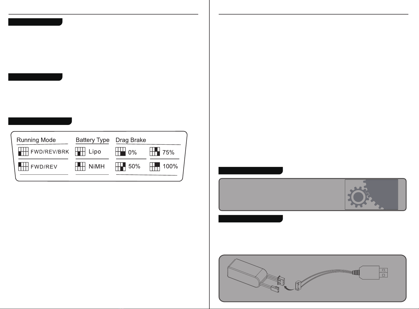
There are three parameters can be set for the ESC, which are "Running mode", "Battery type", "Drag brake", There
are slide switches numbered 1 2 3 4 on the radio panel . The above parameters can be set by dialing down and up.
The specific operation is as follows:
When No. 1 slide switch is on the down, it indicates that the operation mode is set to FWD / REV / BRK.
When No. 1 slide switch is on the up, it indicates that the operation mode is set to FWD/REV.
When No. 2 slide switch is on the down, it indicates that the battery type is set to Lipo.
When No. 2 slide switch is on the up, it indicates that the battery type is set to NiMH.
When No. 3 and No.4 slide switch are on the down, it indicates that the drag brake force is set to 0%.
When No. 3 slide switch is on the down and No.4 slide switch is on the up, it indicates that the drag brake force is set
to 50%.
When No. 3 slide switch is on the up and No.4 slide switch is on the down, it indicates that the drag brake force is set
to 75%.
When No. 3 and No.4 slide switch are on the up, it indicates that the drag brake force is set to 100%
When the transmitter is switched on in normal communication state, keep the channel to be set at the position of the
failsafe setup, and press and hold the BIND button for 3S. The G.LED flashes for 2S, indicating that the setting is
successful. That is, when the receiver cannot receive the signal, it will output the set failsafe value.
Note: The fail-safe function has no default set at the factory and as such must be set manually. If no failsafe setting
has been set, then the receiver will not output anything when signal is lost.
Setup:
EN
Parameter Explanation:
1. Running Mode
FWD/REV/BRK: This mode adopts "double click” reverse mode, that is, when the throttle trigger is pushed from netural
range to the reverse area for the first time, the motor is only braking and will not reverse; when the throttle trigger is
moved back to the netural range and pushed to the reverse area for the second time, it will reverse. This mode is
applicable to general models.
FWD/REV: This mode adopts "one click" reverse mode, that is, when the throttle trigger is pushed from netural range to
the reverse area, the motor immediately generates reverse action, which is generally applied to rock crawler.
Parameter setting method:
When No. 1 slide switch is on the down, it indicates that the operation mode is set to FWD / REV / BRK.
When No. 1 slide switch is on the up, it indicates that the operation mode is set to FWD/REV.
2. Battery Type
There are LiPo and NiMH cells. The low-pressure protection value is different under different types. It can be set according
to the actual use.
Parameter setting method:
When No. 2 slide switch is on the down, it indicates that the battery type is set to Lipo.
When No. 2 slide switch is on the up, it indicates that the battery type is set to NiMH.
3. Drag Brake Force
The drag brake means that when the throttle trigger moves from the forward or reverse area to netural range, it will
produce certain braking force to the motor, the larger the value is, the greater the drag brake force is. Select proper
braking force according to the actual situation.
Parameter setting method:
When No. 3 and No.4 slide switch are on the down, it indicates that the drag brake force is set to 0%.
When No. 3 slide switch is on the down and No.4 slide switch is on the up, it indicates that the drag brake force is set
to 50%.
When No. 3 slide switch is on the up and No.4 slide switch is on the down, it indicates that the drag brake force is set
to 75%.
When No. 3 and No.4 slide switch are on the up, it indicates that the drag brake force is set to 100%.
EN
Setting the Gear Mesh
The gear mesh is the clearance between the pinion and spur gears in your
vehicle. If the motor or gearing components are replaced,check that the
gears are not meshing too tightly as this may cause premature wear.
Charging the Battery
1.Connect the charger to a USB port then connect the battery to the charger.
2.When charging,the Green LED is flash, when charged, the Green LED is stable.
3.Do not let the battery charge unattended!
4. If the battery or charger is hot,disconnect the battery and charger immediately as this may be caused by an internal
short-circuit.
1. Connect the charger's USB port to a power source.
2. Connect the battery to the charger.
15 16

C2078
C2079
C2080
C2081
C2082
C2083
C2084
C2085
C2086
C2045
C2046
C2052
C2087
C2051
C1210
C1169
C2049
C2057
C2058
C2088
C2056
C2060
C2089
C2063
C2090
C2065
C2066
C2067
C2068
C2069
C2091
C2071
C2073
C2074
C2075
C2076
C2021
NOTE
EN
Always charge LiPo batteries on non-flammable, heat-resistant surfaces.
Always use a LiPo-safe bag or container while charging. Do not allow LiPo cells to overheat at any time.Cells which
reach greater than 140 Fahrenheit(60°C) will usually become damaged and will catch fire.
Do not charge the LiPo pack while it is still in the model. Never charge or store battery packs in a vehicle.
Do not discharge LiPo; doing so will damage the battery.
Do not expose LiPo cell to water or moisture at any time.
Do not store battery near open flame or heater.
Do not assemble LiPo cells or pre -assembled packs together with other LiPo cells or packs.
Always store LiPo battery in a secure location away from children.
Always remove the LiPo battery if model is involved in any kind of crash.
Carefully inspect the battery and connectors for even the smallest damage.
CAUTION:Cells may become hot after usage.Allow the pack to cool to room temperature prior to recharging.
Do not allow the electrolyte to get into eyes or on skin.Wash affected areas immediately if they if they come into
contact with electrolyte.Do not alter or modifv connectors or wires of a LiPo battery pack.
Always inspect the condition of the battery before charging and operating.
Do not short circuit the LiPo battery.
Do not have contact with a leaky/damaged battery directly.
Do not charge battery out of recommended temperature range(O°C 45°C).
1.If it is not in use for a long time, unplug and take off the battery to prevent batery leakage
2.Do not open, disassemble, or attempt to repair the battery.
EN
The antenna(s) used for this transmitter must be installed to provide a separation distance of at least 20 cm from all
persons and must not be co-located or operating in conjunction with any other transmitter. End-users and installers
must be provided with antenna installation instructions and transmitter operating conditions for satisfying RF
exposure compliance.
FCC ID: N4ZMG400
This equipment has been tested and found to comply with the limits for a Class B digital device pursuant to part
15 of the FCC rules. These limits are designed to provide reasonable protection against harmful interference in a
residential installation. This equipment generates, uses and can radiate radio frequency energy and, if not installed
and used in accordance with the instructions, may cause harmful interference to radio communications. However,
there is no guarantee that interference will not occur in a particular installation. If this equipment does cause
harmful interference to radio or televison reception, which can be determined by turning the equipment off and on,
the user is encouraged to try to correct the interference by one or more of the following measures:
To assure continued compliance, any changes or modifications not expressly approved by the party responsible for
compliance could void the user's authority to operate this equipment.
This equipment complies with Part 15 of the FCC Rules. Operation is subject to the following two conditions:
(1) This device may not cause harmful interference.
(2) This device must accept any interference received, including interference that may cause undesired operation.
Caution!
The manufacturer is not responsible for any radio or TV interference caused by unauthorized modifications to this
equipment. Such modifications could void the user authority to operate the equipment.
1. The antenna(s) used for this transmitter must be installed to provide a separation distance of at least 20 cm
from all persons and must not be co-lacated or operating in conjunction with any other transmitter.End-users
and installers must be provided with antenna installation instructions and transmitter operating conditions for
satisfying RF exposure compliance.
2. Move all your channels to the desired position.
3. Select [All channels] and then [Yes] in the confirmation box.
• Reorient or relocate the receiving antenna.
• Increase the separation between the equipment and receiver.
• Connect the equipment into an outlet on a circuit different from that to which the receiver is connected.
• Consult the dealer or an experienced radio/TV technician for help.
FIRE HORSE Hood
FIRE HORSE Front and Rear Light Cup Set
FIRE HORSE Hood Mount Set
FIRE HORSE Spare Tire Bracket
FIRE HORSE Rearview Mirror And Wiper
FIRE HORSE Bumper set
FIRE HORSE Lens set
FIRE HORSE Body SHELL
FIRE HORSE handle set
Teraz Tire 19.2 x 13.5 x 56
1:18 Star Style Wheels plastic parts
FMS LIPO Battery 2S LIPO 380mAh
1:18 FIRE HORSE Light set
FMS USB Charger
11221 RECEIVER
HT-TX01 2.4G TRANSMITTER
1:18 050 Motor set
1:18 Plastic Gear set
1:18 Transmission Shaft full set
1:18 FIRE HORSE Screw set
1:18 Drive axle Metal Gear
1:18 M2&M2.5 SCREW NET
1:18 FIRE HORSE Window
1:18 SHOCK PLASTIC PARTS
1:18 FIRE HORSE Connecting Rod
1:18 M4 ALLY BALL
1:18 BALL HEAD
1:18 Steering Hub & Spindle
1:18 FRONT/REAR AXLE parts
1:18 SERVO HORN
1:18 FIRE HORSE MIRROR LENS
1:18 Wheel Hex
1:18 BEARING Set
1:18 Rear Wheel Shaft
1:18 FRONT OUTDRIVE SHAFT
1:18 Gear Box Plastic Parts
1:18 1KG High Torque 3wire Servo
Spare parts list
CE Warning
Appendix 1 FCC Statement
Battery
Motor
ESC&RX
LED
Servo
17 18
Other manuals for 1:18 Fire Horse
1
Table of contents
Other Roc Hobby Motorized Toy Car manuals

Roc Hobby
Roc Hobby 11241 User manual

Roc Hobby
Roc Hobby SCALER MB 1941 User manual

Roc Hobby
Roc Hobby 1:10 Atlas 4x4 User manual

Roc Hobby
Roc Hobby ROC11242RTRCE User manual

Roc Hobby
Roc Hobby 1:12 TYPE82 KUBELWAGEN User manual

Roc Hobby
Roc Hobby 1:18 Fire Horse User manual

Roc Hobby
Roc Hobby DPROC001RS User manual
Popular Motorized Toy Car manuals by other brands

Meccano
Meccano AUTOCROSS RC instructions

Fisher-Price
Fisher-Price Power Wheels DC Super Friends Batman Lil' Quad... Owner's manual with assembly instructions

Mattel
Mattel Hot Wheels MOTORIZED KART MANIAX Stunt Pit instructions

WELD
WELD GALM OVERDOSE Assembly manual

Tamiya
Tamiya 58657 manual

Jamara
Jamara 461835 instructions