Roca BROADWAY SPA Guide
1
Instructions for Installation
BROADWAY SPA

2
TABLE OF CONTENTS
GENERAL SPECIFICATIONS .............................................................................................................................. 3
1. RECEIVING THE EQUIPMENT ...................................................................................................................... 4
2. PREPARING THE PLACE FOR THE INSTALLATION ................................................................................. 4
3. POSITIONING THE SPA ................................................................................................................................... 4
4. ELECTRICAL CONNECTIONS ......................................................................................................................... 4
4.1. GROUNDING CABLE CONNECTION................................................................................................. 5
4.2. MAINS CONNECTION............................................................................................................................ 5
5. HYDRAULIC CONNECTION ........................................................................................................................... 5
6. FILLING AND EMPTYING THE SPA .............................................................................................................. 5
7. VENTILATION ..................................................................................................................................................... 6

3
CONGRATULATIONS AND THANK YOU FOR
PURCHASING THIS ROCA PRODUCT
This spa has been designed, manufactured and checked by our technical
staff. It must be fitted in compliance with the regulations in force, and
the corresponding instructions should be followed.
BREACH OF THIS CONDITION RENDERS THE PRODUCT WARRANTY
NULL AND VOID.
This spa has been designed for private use.
GENERAL SPECIFICATIONS
AIR MASSAGE:
- blower with air heater 1,1 kW (0,8 kW blower and 0,3 kW air heater),
- 75 holes.
WATER MASSAGE:
- Massage & ltration pump - 1,8 kW,
- Jets:
- fixed mini jets (A) - 16 pcs
- large rotary jets (B) - 2 pcs
- large fixed directional jets (C) - 6 pcs
- directional mini ozone jet (D) - pcs
- 4 air regulators:
DISINFECTION:
- 1 ozone generator (10W) 250mg/h,
- UV lamp (optional) – no ozone jet.
FILTERING:
- Filter cartridge.
WATER HEATER ELEMENT:
- 2 x 3 kW electric heater.
SPECIFICATIONS:
- Capacity - 880 litres.
- Dimensions - 1930/1930/870 mm.
- Depth - 750 mm.
- Weight - 300 kg (without water).
- Power consumption:
8,9 kW (L1-13 A, L2-13 A, L3-13,8 A) - version 3N 400V AC 50Hz,
- white underwater LED light,
- multi-color light (optional),
- LED spotlight – 24 points (optional),
- 3 polyurethane cushions (gray in a standard option),
- wooden panel in mahogany or pine colour (optional),
- plastic panel in gray, mahogany or pine (optional),
- wooden stairs in mahogany or pine colour (optional),
- thermal cover (optional),
Material and construction:
Acrylic strengthened by laminated polyester on an aluminum frame.
SPAs with panels are installed on wooden frame only.
G
G
A
A
A
G
Skimmer filter
E
E
C
D
B
C
C
C
G
A-
-
-
-
-
- control panel
-
fixed mini jets
large rotary jets
large fixed directional jets
directional mini ozone jet
water suction
aeration regulators
B
C
D
E
F
G
STANDARD
SETHEAT
F
80
750
600
15
806
+20
0
845
20
600
750
80
4
1. RECEIVING THE EQUIPMENT
The spa should reach its destination in its original packaging. Once the
packaging has been removed, check the spa fully before it is installed
and report any anomaly.
Do not lift the spa using the lter equipment or the pipes.
Do not stand the pool on its edge. Always stand it on its legs.
During the installation, check that the interior of the spa is protected by
the covering included with the equipment.
The electrical installation and pipe connections must be carried out by
authorised installers.
2. PREPARING THE PLACE FOR THE INSTALLATION
The Broadway SPA can function indoors and outdoors. It must be
installed on a firm base to prevent it from sinking.
When choosing the location for the spa, a series of requirements must
be taken into account:
- If you have decided to install the spa indoors, bear in mind the
thoroughfares required for transporting it to its final location.
- Proper electrical supply and ensured efficiency of the electrical
connection in respect of the equipment - for standard equipment the
rated power consumption is ab 8,9 kW, 3N 400V AC, 50 Hz (5x4 mm2) -
with regard to the safety of the users, in all cases the supply cable must
be protected by means of a differential-current switch with the standard
rated switch off current of 30 mA),
- An earth connection compliant with current legislation is essential.
- Access to interior components through the side panels for post-
installation maintenance.
- You must also bear in mind how you are going to fill and empty the
spa. The floor must be level.
- There must be adequate ventilation in closed interior locations.
- You must bear in mind the materials used on the wall and ceilings, since
the humidity generated by the spa requires steam-resistant materials.
- Due to unavoidable splashing, the floor must be highly-resistant to
water, such as tiles or plastic coverings. If carpets are used, they must
be treated to avoid bacteria from damp. Use special sailing carpets or
rugs. Parquet or wooden floors are not advisable unless they have been
duly treated for this kind of use, such as wood for gardens or outdoor
buildings. In any case, make sure that the floor has a gradient of 2%
towards a drain installed in the room.
3. POSITIONING THE SPA
- When installing the spa in a corner or next to a side wall, remember
to leave 0,5 metres or connection or installation work or fit trap doors
with a minimum size of 1700x700 mm for accessing all the sides for
post-installation maintenance.
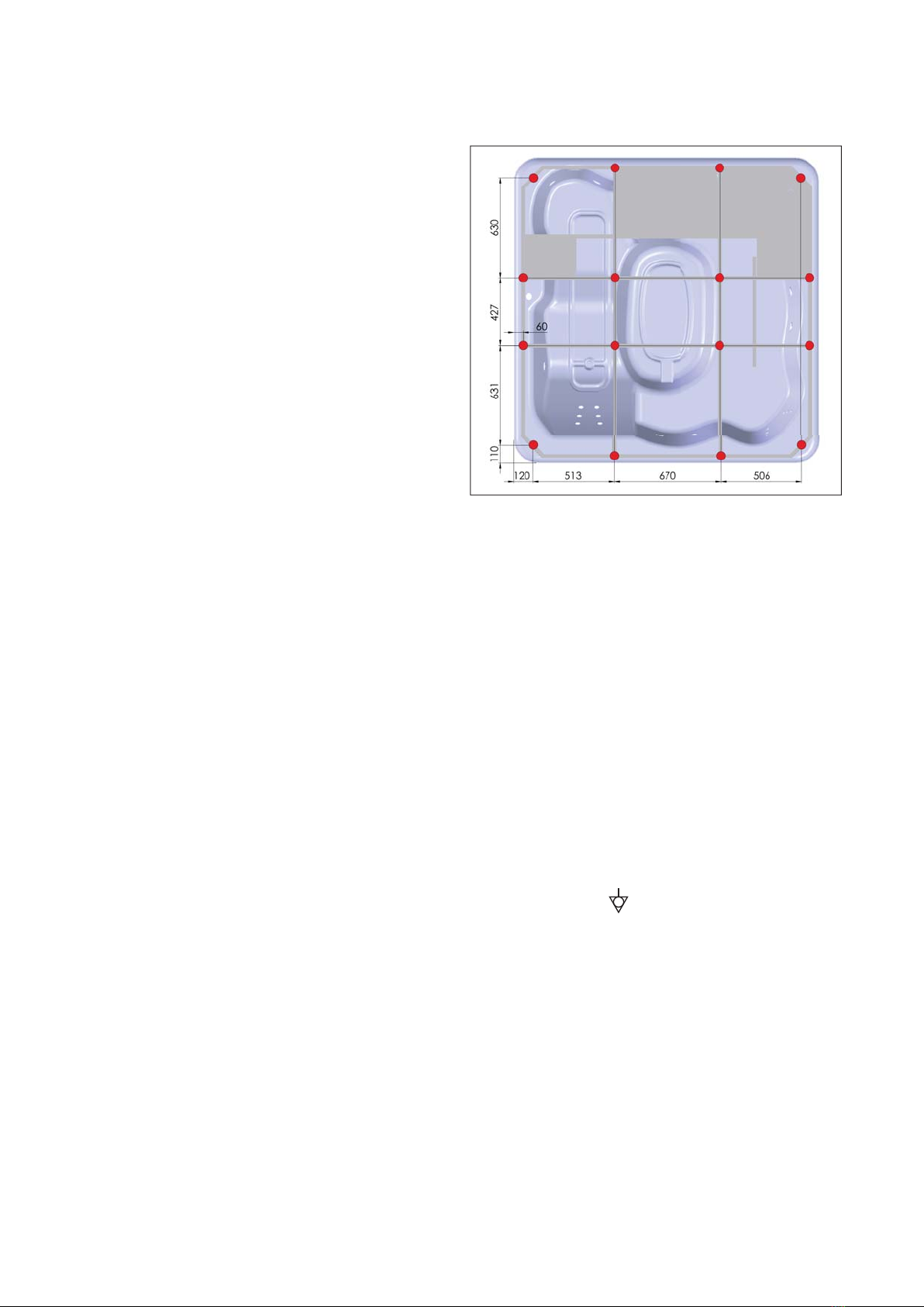
- The floor should be very well leveled. All the bath legs should be on a
solid and hard surface. The total weight of the bath with water is about
1350 kg. The weight of the bath should be equally spread over the 16
bath legs. The surface load is 362 kg/m2.
- This spa cannot be embedded. Do not obstruct access to the side
panels.
4. ELECTRICAL CONNECTIONS
Broadway SPA requires at most ca. 8,9 kW of power. In both cases,
the minimum cross-section of the cord should be at least 5x4 mm2. In
the case of tubs installed outdoors, a cord with insulation resistant to
deterioration caused by weather conditions is required. Protect the
cord against mechanical damage. If the insulation or cord is damaged,
always replace it due to the risk of electric shock.
For 5x4 mm2cords, protect the tub’s power cord with a C-type residual
current device and a trigger current of 16 A. For safety reasons, always
connect the tub’s power cord to the mains using an electrical connection
protected by a residual current device with a rated cut-off current of 30
mA. It is recommended to check the residual current device periodically,
according to the guidelines for testing and resetting such devices.
The SPA tub should be connected to the building’s electrical wiring
permanently. The electrical wiring should be equipped with the
appropriate manualcut-off mechanism,enabling theopening ofcontacts
on each power supply pole. In addition, equipotential bondings must
be made using the clamp located on the tub support frame. The
minimum cross-section of the equalizer power cord is 4 mm2.

5
Skimerfilter
1930
1930
Sewage connection,
50 mm
Water connection,
1/2", for water filling
Control panel
100
350
550
1300
3N 400 AC
8 9
(5x4 mm )
V electric connection
with , kW efficiency protected
2
STANDARD
SETHEAT
All electrical connections should be made by a qualified
electrician.
For safety reasons, check the effectiveness of the anti-
electric shock protection from time to time by pressing the
TEST button on the residual current device. If the power is
not turned off immediately after pressing the button,
unplug the tub manually and contact a qualified specialist.
Do not use the SPA tub if the protections do not function
properly.
To prevent activation of the bath without water, switch off the electrical
power by pressing the test button on the differential-current switch.
4.1. GROUNDING CABLE CONNECTION
In order for the residual current device and the
tub it self to function properly, a grounding
cable with a cross-section of at least 2,5 mm2
must be installed. Connect the cable to the
frame, as illustrated. Connect the other end of
the cable to the protective grounding of the
building’s electrical wiring.
4.2. MAINS CONNECTION
As the bathtub is protection class I equipment it has to be permanently
connected to power supply (TN-S type) using IP X5 junction box. It is
recommended to install the connection box in area I (under the bath-
tub) close to other electrical devices of the bathtub (more than 20 cm
above the floor).
The bathtub must never be connected using a plug.
Zone 0 is the area inside the bath.
Zone 1 is the zone 0 area plus the space up to 2,25 m above the floor.
Zone 2 is the zone 1 area extended by 0,6 m, again up to 2,25 m above
the floor.
Zone 3 is the area reaching 2,4 m beyond zone 2, up to 2,25 cm above
the floor.
2,4 m
2,4 m
Zone 1 Zone 1
Zone 0
Zone 3
Zone 3
Zone 3
Zone 2
Zone 2
2,25 m
0,6 m 0,6 m
0,2 m
5. HYDRAULIC CONNECTION
For the connection, use PVC pipes and appropriate adhesive for this
type of material. Do not use metal pipes.
Make sure that there are no accumulated bags of air or water in the
fill or empty connection. The emptying circuit must guarantee perfect
emptying and, if the use of the drain so allows, a U-bend to prevent
bad smells.
Also, where required, the fill and empty circuits must also be fitted with
anti-backflow devices to prevent retrosuction..
Once the installation is complete, start up the equipment and check that
the joints are watertight. Mark the water level in the spa, leave it for 24
hours and check that it has not gone down.
6. FILLING AND EMPTYING THE SPA
Never use the air blower circuit to fill the spa.
The bath can be connected to the water and sewage systems
permanently or the bath can be filled and drained by means of flexible
hoses disconnected after each operation. The flexible hose set of
the bath includes a T-pipe with a 1/2” coupling for filling of the bath
through the hydro-massage jets. The fixed piping system includes
release valves located near the skimmer-filter; at the outlets of which
fixed or removable hose connection with the sewage system should
be provided.
It is recommended that the bath is permanently connected to the
sewage system due to the risk of water overflowing through the
emergency overflow system.

6
7. VENTILATION
The possible high temperature of the water in the spa (approximately
39 ºC) leads to steam condensation.
The spa room must have adequate ventilation. If it does not, it is rec-
ommended that you install a dehumidifier to keep the air humidity at
a constant temperature and prevent steam from condensing on the
ceiling and on the floor.
For the correct maintenance of the wood, the relative air humidity in
the room must be kept below 65% when the spa is not being used.
During use and due to the evaporation caused by the hydromassage
and the movement of the water, this value normally reaches 90 or 95%.
The air humidity can be kept constant by the use of fans controlled
by hygrostats or dehumidifiers adapted to the size of the room. Your
installer or distributor can offer you advice on this. If the room has air
conditioning, the condenser is not necessary. If the spa is outdoors or
in an open space, these apparatuses are not necessary.

7

8
20150707
8S0035000
Roca S.R.L.
Via Leonardo da Vinci, 24
20080 Casarile (Milano)
Italia
Tel. +39.02.900.251
Fax.+39.02.905.21.74
Roca S.A.
Apartado 575
Ponte Madalena
2416-905 Leiria
Portugal
T.: +351 244 720 000
F.: +351 244 722 373
Roca Limited
Samson Road
Hermitage Ind. Estate
Coalville, Leics. LE67 3FP
United Kingdom
Tel. +44.(0)1530.83.00.80
Fax.+44.(0)1530.83.00.10
ROCA Maroc, S.A.
Route de Marrakech, km 2.5
B. P. 571 - 26000 - Settat
Maroc
Telf : +212.(0)23.40.59.41
+212.(0)23.40.03.39
Fax : +212.(0)23.40.59.42
Roca GmbH
Feincheswiese 17
56424 Staudt
Deutschland
Tel. +49.(0)2602.93610
Fax.+49.(0)2602.936.122
Roca Polska Sp. z o. o.
ul. Wyczolkowskiego 20,
44-109 Gliwice
Polska
Tel. +48.(0)32 339 41 00
Fax.+48.(0)32 339 41 01
Roca Argentina S.A
Camino General Belgrano, 2873
1824 - Lanús Este
Buenos Aires
Argentina
Tel. +54.(0)114.230.96.39
Fax:+54.(0)114.246.95.56
Roca S.A.R.L.
BP 90422
95005 Cergy Pontoise Cedex
France
Tél. +33.(0)1.34.40.39.00
Fax.+33.(0)130.37.02.65
+33.(0)134.64.13.55
Kalevit Roca Saniter Seramik Sanayi, A.S.
Büyükdere Cad.
Kaleseramik Binasi
80620 Levent – Istanbul
Turkey
Tel. +90.212.270.70.00
Fax.+90.212.268.68.89
(available in Spain only) (available in Spain only)
Table of contents
Other Roca Hot Tub manuals

Roca
Roca LINEA A24T0 0 Series User manual

Roca
Roca SPA BROADWAY ROUND Instruction Manual

Roca
Roca BROADWAY COMPACT Instruction Manual

Roca
Roca BROADWAY Instruction Manual

Roca
Roca Broadway Round User manual

Roca
Roca Broadway Maxi Instruction Manual

Roca
Roca SPA BROADWAY ROUND User manual

Roca
Roca BROADWAY COMPACT User manual

Roca
Roca Broadway Maxi User manual

Roca
Roca BROADWAY FAMILY User manual
Popular Hot Tub manuals by other brands

Bestway
Bestway Lay-Z-Spa 54189 manual

Jacuzzi
Jacuzzi ARGA ARG101C0110 Use & maintenance

Morphy Richards
Morphy Richards Essentials PC4006 user manual

Softub
Softub PRESTIGE Owners Manual Water Treatment Guide

JNJ SPAS
JNJ SPAS SPA-318 Programming instructions

KIRAMI
KIRAMI Comfort Family Instructions for use
 owner's manual")


