4
2. PREPARING THE PLACE FOR THE INSTALLATION
The Broadway Round spa can function indoors and outdoors. It must
be installed on a firm base to prevent it from sinking.
When choosing the location for the spa, a series of requirements
must be taken into account:
- If you have decided to install the spa indoors, bear in mind the
thoroughfares required for transporting it to its final location.
- The electrical connection of the equipment must be carried out
with a 3 conductor cable with a section of 4 mm2and ready for 230
VAC (the nominal power consumed by the standard equipment is
equal to 5,0 kW).
- An earth connection compliant with current legislation is essential.
- Access to interior components through the side panels for post-
installation maintenance.
- You must also bear in mind how you are going to fill and empty
the spa. The floor must be level. (Fig. 3).
- There must be adequate ventilation in closed interior locations.
- You must bear in mind the materials used on the wall and ceilings,
since the humidity generated by the spa requires steam-resistant
materials.
- Due to unavoidable splashing, the floor must be highly-resistant
to water, such as tiles or plastic coverings. If carpets are used, they
must be treated to avoid bacteria from damp. Use special sailing
carpets or rugs. Parquet or wooden floors are not advisable unless
they have been duly treated for this kind of use, such as wood for
gardens or outdoor buildings. In any case, make sure that the floor
has a gradient of 2% towards a drain installed in the room.
3. POSITIONING THE SPA
- For appropriate operating conditions, the spa must be positioned
on a carefully levelled, firm base.
- The weight of the full spa and with three people in it is approxima-
tely 1000 kg. This weight is supported on 9 points - the legs - with a
load on the floor of 400 kg/m2.
- Level the spa by adjusting the legs (Fig. 3).
- Position the spa in a way that best enables maintenance through
the wooden panels.
-When installing the spa in a corner or next to a side wall, remember
to leave 0.5 metres or connection or installation work or fit trap doors
with a minimum size of 1700x700 mm for accessing all the sides for
post-installation maintenance.
- This spa cannot be embedded. Do not obstruct access to the side
panels.
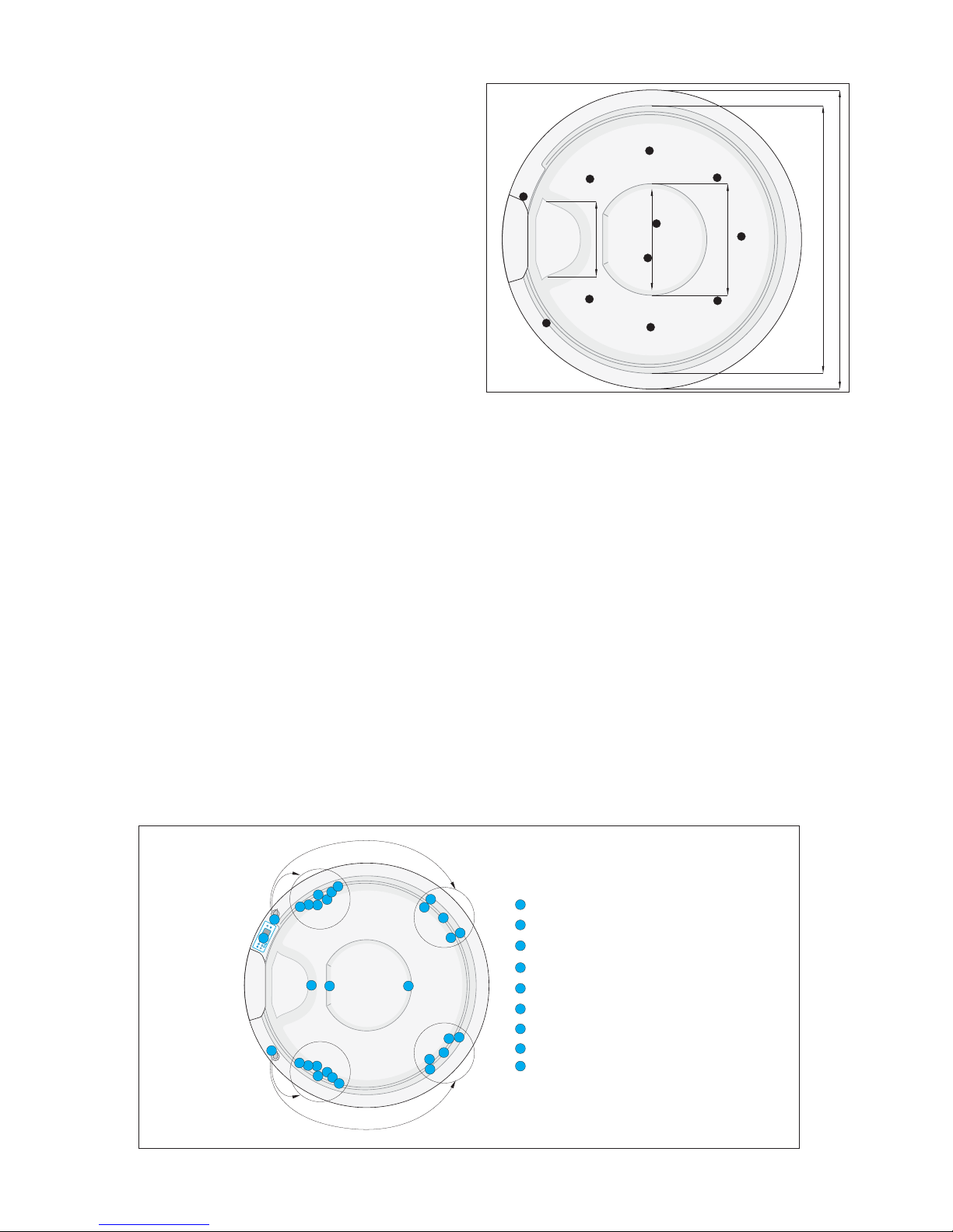
The following diagrams show the distribution of the support points
and the position of the spaces inside the spa.
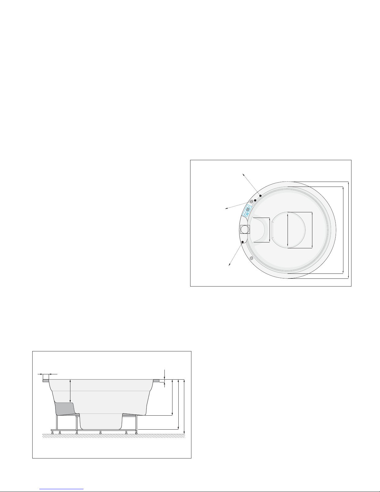
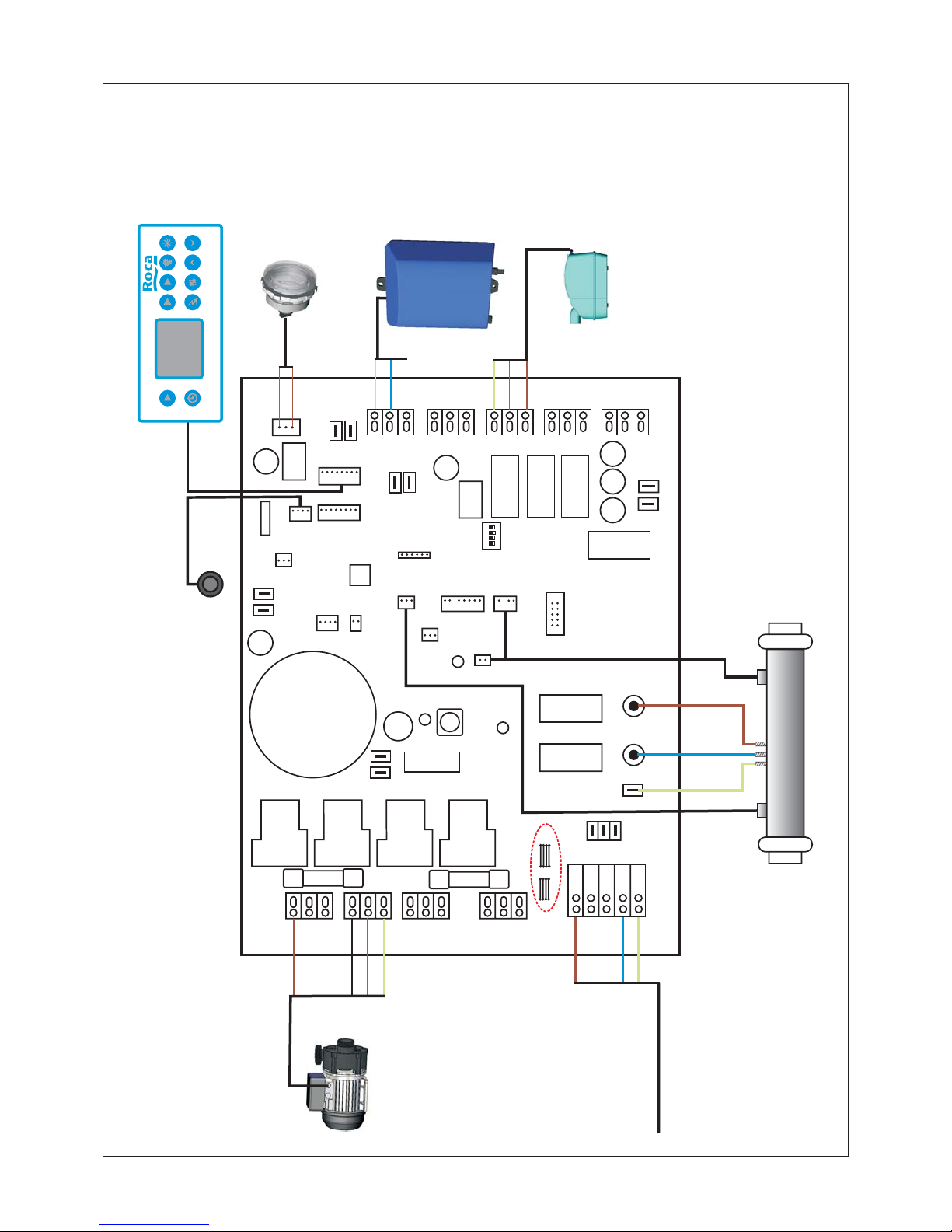
4. ELECTRICAL CONNECTIONS
The electrical installation must be carried out by an authorised elec-
trician. The internal connections of the equipment have been made
at the factory (Fig. 4). The electrical installation of the spa must be
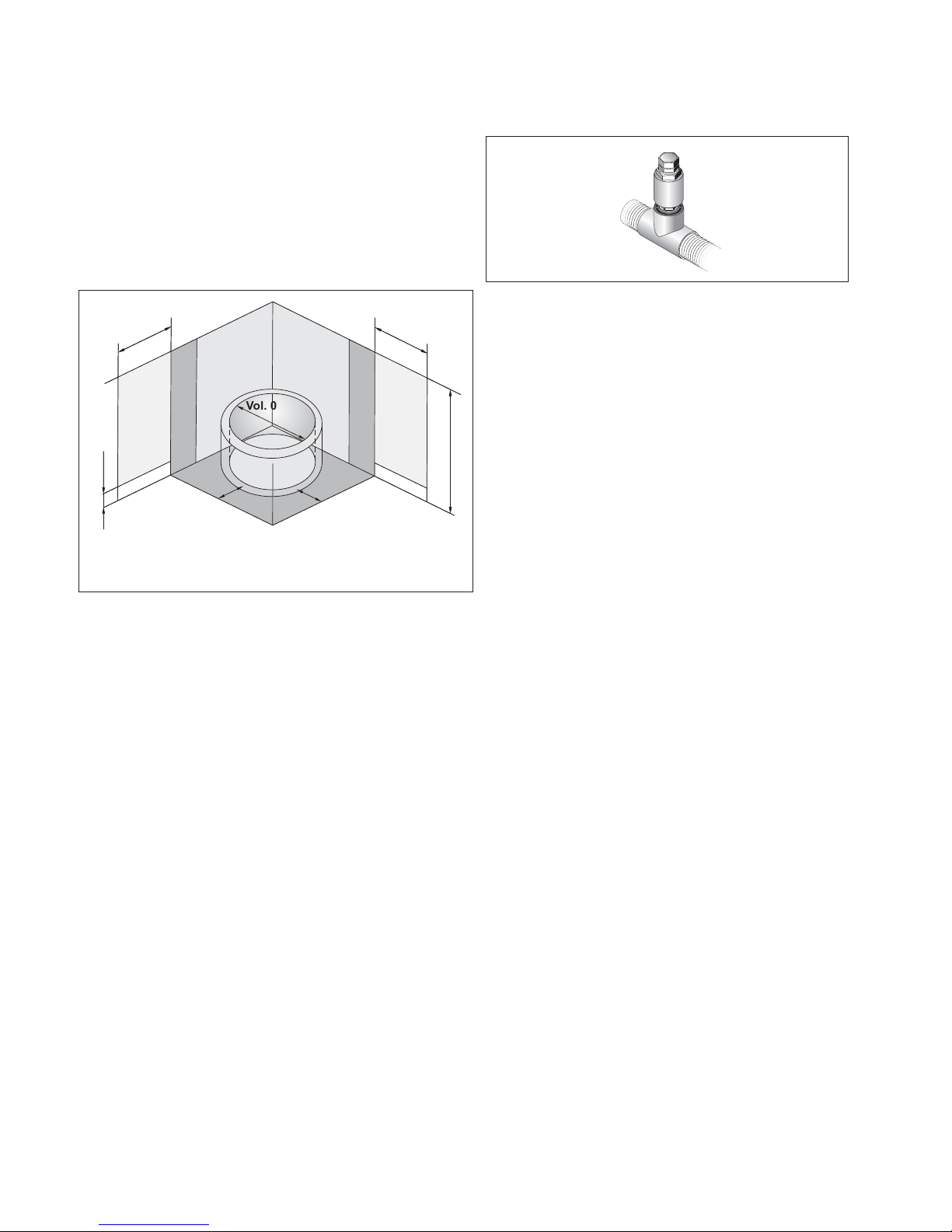
protected by a 30 mA differential switch and a 25 A magnetother-
mal switch with omnipolar disconnection devices and a distance
between contacts of at least 3 mm. Both switches must be situated
outside the volumes as shown in fig. 5.
1765
1580
660
600
440
Skimerofiltr
Electric connection
1 phase 230V 3 x 4 mm2
FILTER
LIGHT
JETS2
JETS3JETS1
DOWN
UP
AIR
CLOCKECONO
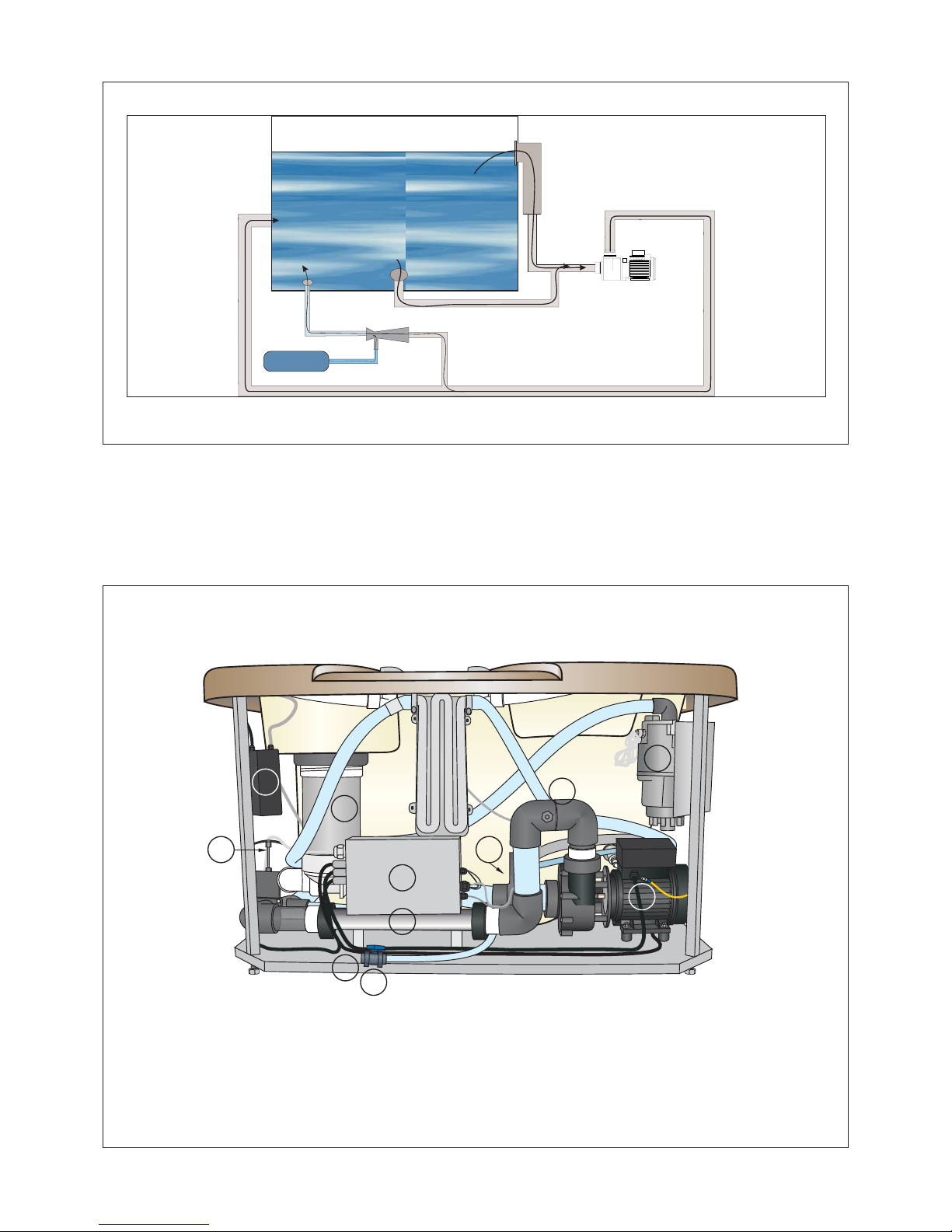
2
1
3
Sewage connection
50 mm
Water connection 1/2”
for water filling
4.1. EARTH CONNECTION
For the circuit-breaker to function correctly, there must be an insta-
llation with an earth connection in the home.
4.2. EQUIPOTENTIAL CONNECTION
The spa has a terminal for a 4 mm2section cable which joins all the
metal parts of the apparatus electrically and which must be connec-
ted to the equipotential connections grid of the home. This terminal
must not be connected to the mains supply earth of the spa.
4.3. MAINS SITUATION
The mains supply cable of the spa must be connected to a fixed
installation. A plug is not acceptable.
The electrical installation must be compliant with current legisla-
tion governing low voltage. For this, it is important to bear in mind
that four protection blocks are established where the spa is to be
installed, defined as shown in the following diagram, (fig. 5). Where
block 3 is appropriate for the mains, or a false ceiling with a height
of over 2.25 m.
4.4. MAINS CONNECTION
For the mains connection, the following must be taken into ac-
count:
- The power supply of the spa must be permanently connected to
a fixed electrical conduit.
550
765
830
355
90
40
Fig. 3
Fig. 4


 owner's manual")